US1761853A - Starting-motor-control mechanism - Google Patents
Starting-motor-control mechanism Download PDFInfo
- Publication number
- US1761853A US1761853A US50696A US5069625A US1761853A US 1761853 A US1761853 A US 1761853A US 50696 A US50696 A US 50696A US 5069625 A US5069625 A US 5069625A US 1761853 A US1761853 A US 1761853A
- Authority
- US
- United States
- Prior art keywords
- motor
- arm
- starting
- contact
- control mechanism
- Prior art date
- Legal status (The legal status is an assumption and is not a legal conclusion. Google has not performed a legal analysis and makes no representation as to the accuracy of the status listed.)
- Expired - Lifetime
Links
Images
Classifications
-
- F—MECHANICAL ENGINEERING; LIGHTING; HEATING; WEAPONS; BLASTING
- F02—COMBUSTION ENGINES; HOT-GAS OR COMBUSTION-PRODUCT ENGINE PLANTS
- F02P—IGNITION, OTHER THAN COMPRESSION IGNITION, FOR INTERNAL-COMBUSTION ENGINES; TESTING OF IGNITION TIMING IN COMPRESSION-IGNITION ENGINES
- F02P5/00—Advancing or retarding ignition; Control therefor
- F02P5/04—Advancing or retarding ignition; Control therefor automatically, as a function of the working conditions of the engine or vehicle or of the atmospheric conditions
- F02P5/145—Advancing or retarding ignition; Control therefor automatically, as a function of the working conditions of the engine or vehicle or of the atmospheric conditions using electrical means
- F02P5/155—Analogue data processing
- F02P5/1558—Analogue data processing with special measures for starting
-
- Y—GENERAL TAGGING OF NEW TECHNOLOGICAL DEVELOPMENTS; GENERAL TAGGING OF CROSS-SECTIONAL TECHNOLOGIES SPANNING OVER SEVERAL SECTIONS OF THE IPC; TECHNICAL SUBJECTS COVERED BY FORMER USPC CROSS-REFERENCE ART COLLECTIONS [XRACs] AND DIGESTS
- Y02—TECHNOLOGIES OR APPLICATIONS FOR MITIGATION OR ADAPTATION AGAINST CLIMATE CHANGE
- Y02T—CLIMATE CHANGE MITIGATION TECHNOLOGIES RELATED TO TRANSPORTATION
- Y02T10/00—Road transport of goods or passengers
- Y02T10/10—Internal combustion engine [ICE] based vehicles
- Y02T10/40—Engine management systems
Definitions
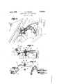
- My invention relates to starting switch controls and more particularly to a device for use in connection with the operative mechanism of motor vehicles of theFord type, to permit operation of the starting motor only when .the ignition for the main motor-is set for a retarded spark, the principal object of the invention being to prevent damage to the start-- the starting motor and spark lever rod with my control mechanism applied thereto, a portion of the control mechanism being broken away to illustrate the electrical connection.
- Fig. 3 is a detail perspective View of the contact arm and its mounting.
- Fig. 4 is a detail perspective View of the brush for actuating the contact arm.
- 1 designates a portion of the motor vehicle, 2 a starting motor, and 3 a battery of any conventional type, permanently mounted on the frame of the vehicle in any suitable manner.
- 4 designates a part of the spark lever rod which extends from the steering wheel (not shown) in the usual manner and in such proximity to the starting motor as to provide co operative relationship between the elements of the control mechanism hereinafter de scribed.
- a mounting plate 6 Fixed to the frame of the vehicle, adjacent the starting motor, preferably by screws 5, is a mounting plate 6, carrying a spring arm 7 which extends over the motor 2 and particu larly over a contact member 8 grounded on the starter housing and through which current is passed to the starting'motor from the battery when proper contacts are made, the
- the detail construction of the brush 10 is preferably that shown in the drawings; comprising a single piece of strap metal formed into a U 11 which fits over the rod and is securely attached thereto by a bolt 12, one end of the strap being extended downwardly and curved, as at 13, to provide for wiping contact thereof with the curved lip 9 on the flexible arm 7' of the mating control member.
- the arm 7 carries a contactmember let directly over the contact member 8 on the starter housing, the member preferably con sisting of a bolt 15 which extends through a non-conductive bushing 16 in an opening 17 in the arm 7, and through non-conductive washers 18 and 19 above and below the arm 7 to insulate the bolt from the arm, the bolt and washers being held securely to the'arm by a head 14 and a nut, the latter being located above the upper Washer 18 and in conductive relation to the bolt 15.
- the contact 7 member8 consists of a female stud that is removably applied to the standard stud 2"on the starting motor and the contact member 14 of a bolt which may be removably mounted on the spring arm. Consequently, eitherjof the contact members maybe replaced should they become oxidized or otherwise unfit for use.
- the operator When it is desired to start the vehicle motor the operator first pulls his spark lever in a clockwise direction, which is the direction in which itmust be turned to retard the spark, such turning of the lever throwing the brush arm 13 intocontact With thelip on the end of the resilient arm 7 and bending the arm downwardly toward the starting motor until the contact point 14 on the arm contacts the s point 8 on the motor, whereupon a circuit s 1 closed through the motor and battery which energizes the starting motor so that it can perform its function ofstartingi the Lmain 7 motor.
Landscapes
- Engineering & Computer Science (AREA)
- Signal Processing (AREA)
- Chemical & Material Sciences (AREA)
- Combustion & Propulsion (AREA)
- Mechanical Engineering (AREA)
- General Engineering & Computer Science (AREA)
- Electric Propulsion And Braking For Vehicles (AREA)
Description
June 3, 1930. I w, WALKER 1,761,853
I STARTING MOTOR CONTROL MECHANISM Filed Aug. 17, 1925 INVENTOR ATTORNEY Patented June 3, 1930 UNITE sATEs PATENT OFFICE WILLIAM D. WALKER, or KANSAS CITY, MISSOURI STARTING-MOTOR-CONTBOL MECHANISM Application filed August 17, 1925. Serial No. 50,696.
My invention relates to starting switch controls and more particularly to a device for use in connection with the operative mechanism of motor vehicles of theFord type, to permit operation of the starting motor only when .the ignition for the main motor-is set for a retarded spark, the principal object of the invention being to prevent damage to the start-- the starting motor and spark lever rod with my control mechanism applied thereto, a portion of the control mechanism being broken away to illustrate the electrical connection.
Fig. 3 is a detail perspective View of the contact arm and its mounting.
Fig. 4 is a detail perspective View of the brush for actuating the contact arm.
Referring more in detail to the drawings:
1 designates a portion of the motor vehicle, 2 a starting motor, and 3 a battery of any conventional type, permanently mounted on the frame of the vehicle in any suitable manner. 4 designates a part of the spark lever rod which extends from the steering wheel (not shown) in the usual manner and in such proximity to the starting motor as to provide co operative relationship between the elements of the control mechanism hereinafter de scribed.
Fixed to the frame of the vehicle, adjacent the starting motor, preferably by screws 5, is a mounting plate 6, carrying a spring arm 7 which extends over the motor 2 and particu larly over a contact member 8 grounded on the starter housing and through which current is passed to the starting'motor from the battery when proper contacts are made, the
end of the arm 7 having .a down-turned lip 9 at its free end for engagement by a brush 10 that is rigidly fixed to the spark lever 4. v
The detail construction of the brush 10 is preferably that shown in the drawings; comprising a single piece of strap metal formed into a U 11 which fits over the rod and is securely attached thereto by a bolt 12, one end of the strap being extended downwardly and curved, as at 13, to provide for wiping contact thereof with the curved lip 9 on the flexible arm 7' of the mating control member.
The arm 7 carries a contactmember let directly over the contact member 8 on the starter housing, the member preferably con sisting of a bolt 15 which extends through a non-conductive bushing 16 in an opening 17 in the arm 7, and through non-conductive washers 18 and 19 above and below the arm 7 to insulate the bolt from the arm, the bolt and washers being held securely to the'arm by a head 14 and a nut, the latter being located above the upper Washer 18 and in conductive relation to the bolt 15. i A
. Interposed between the nut 20 and a similar nut 21 on the bolt 15' is the terminal ring 22 of a circuit wire 23 leading to the battery, so that current may be conducted from the battery to the starting motor when connection is made between'the contacts 8 and 14.
In this preferred construction the contact 7 member8 consists of a female stud that is removably applied to the standard stud 2"on the starting motor and the contact member 14 of a bolt which may be removably mounted on the spring arm. Consequently, eitherjof the contact members maybe replaced should they become oxidized or otherwise unfit for use.
Assuming the parts to be constructed and assembled as described, and the curvature of V the lip .13 of the brush arm 10 being such as to retard contact of the starter contact-s until the spark lever has been turned sufficiently in a clockwise direction to insure a retarded spark in the main motor, the operation and use of the device is as follows:
When it is desired to start the vehicle motor the operator first pulls his spark lever in a clockwise direction, which is the direction in which itmust be turned to retard the spark, such turning of the lever throwing the brush arm 13 intocontact With thelip on the end of the resilient arm 7 and bending the arm downwardly toward the starting motor until the contact point 14 on the arm contacts the s point 8 on the motor, whereupon a circuit s 1 closed through the motor and battery which energizes the starting motor so that it can perform its function ofstartingi the Lmain 7 motor.
When the main motor is started the spark is advanced by rotating thespark control lever in an fiIltl-ClOCkWiSG direction, this" spark eadvanc ngoperat on IQI-IIOVIIIg the brush arm 13. irom contact withthe fiexible arm 7 and? "ermitting thearmtoreturnto through vthe -starting motor and. discontinuing coperation ofthe latterw h contro lingthestartmg motor the-spark lever,jd amage to thestarting-motor because ofvback fire induced by an ad vanced Should ei her of normally spaced .fromthemotor and having r a downwardly inclined. free, end, a contact sparkieebfiamd and am e ompa rrangement of parts is aiiorded because of the eliminati onjoigseparate lever mechanism for h s rtmg m or. 1
particularly the point ,8)
otherwise unfitioruse, it may be removed and replaced byja fresh point without mateial exp n eo i con n nc -"r ;;What I claim and desire to secure by LettersePatentis]: 5' v I;n an automobile starting motor, control switch a bracket vcomprising a plate secured to -the fr-ameofi the automobile in spaced relation with said motor anda flexible arm carried by said'arm, and a cam-like. finger on the spark control rodofthe automobile mov- V able into wiping engagement with said in cllned ffree end when the rod s, turned in sparkretarding direction for flexing the arm I to move said-contact; intoengagement with the stationary contact'of, the starting motor. Intestimony whereof I affix my signature.
WILLIAM n-wALKER. v p e M normal position 5 therebyopening the circuit the contact p oiiitsxbut I i become oxidized, or. i
Priority Applications (1)
| Application Number | Priority Date | Filing Date | Title |
|---|---|---|---|
| US50696A US1761853A (en) | 1925-08-17 | 1925-08-17 | Starting-motor-control mechanism |
Applications Claiming Priority (1)
| Application Number | Priority Date | Filing Date | Title |
|---|---|---|---|
| US50696A US1761853A (en) | 1925-08-17 | 1925-08-17 | Starting-motor-control mechanism |
Publications (1)
| Publication Number | Publication Date |
|---|---|
| US1761853A true US1761853A (en) | 1930-06-03 |
Family
ID=21966826
Family Applications (1)
| Application Number | Title | Priority Date | Filing Date |
|---|---|---|---|
| US50696A Expired - Lifetime US1761853A (en) | 1925-08-17 | 1925-08-17 | Starting-motor-control mechanism |
Country Status (1)
| Country | Link |
|---|---|
| US (1) | US1761853A (en) |
-
1925
- 1925-08-17 US US50696A patent/US1761853A/en not_active Expired - Lifetime
Similar Documents
| Publication | Publication Date | Title |
|---|---|---|
| US1761853A (en) | Starting-motor-control mechanism | |
| US2679557A (en) | Starter ignition switch | |
| US2121651A (en) | Switch | |
| US2702327A (en) | Direction signal switch mechanism | |
| US2644864A (en) | Battery switch | |
| US2301250A (en) | Interrupting switch | |
| US2596440A (en) | Turning signal device for automotive vehicles | |
| GB444655A (en) | Improvements in or relating to safety switches for automobile vehicles | |
| US1497241A (en) | Switch | |
| US1546474A (en) | Electric switch and handle | |
| US1549524A (en) | Circuit-control device for automobiles | |
| US2653197A (en) | Parking brake indicator light | |
| US1239236A (en) | Electric-circuit closer for automobiles. | |
| US2542411A (en) | Circuit breaker | |
| US1403222A (en) | Electric switch | |
| US1669888A (en) | Ignition device | |
| US1887238A (en) | Engine starting system | |
| US1632530A (en) | Circuit closer | |
| US1564159A (en) | Motor-car starting-switch protector | |
| US1325016A (en) | Magneto-circuit breaker | |
| US3025362A (en) | Ignition timer for internal combustion engines | |
| US1375390A (en) | Timer-cover device | |
| US1901607A (en) | Outdoor switch contact | |
| US798992A (en) | Contact-breaker for sparkers. | |
| US1595232A (en) | Electric switch |