US1761846A - Carburetor - Google Patents
Carburetor Download PDFInfo
- Publication number
- US1761846A US1761846A US657543A US65754323A US1761846A US 1761846 A US1761846 A US 1761846A US 657543 A US657543 A US 657543A US 65754323 A US65754323 A US 65754323A US 1761846 A US1761846 A US 1761846A
- Authority
- US
- United States
- Prior art keywords
- valve
- nozzle
- chamber
- engine
- outlets
- Prior art date
- Legal status (The legal status is an assumption and is not a legal conclusion. Google has not performed a legal analysis and makes no representation as to the accuracy of the status listed.)
- Expired - Lifetime
Links
- 239000012530 fluid Substances 0.000 description 10
- 239000000446 fuel Substances 0.000 description 6
- 238000010276 construction Methods 0.000 description 4
- 238000007599 discharging Methods 0.000 description 3
- 230000015572 biosynthetic process Effects 0.000 description 2
- 230000005484 gravity Effects 0.000 description 2
- 239000000203 mixture Substances 0.000 description 2
- OKTJSMMVPCPJKN-UHFFFAOYSA-N Carbon Chemical compound [C] OKTJSMMVPCPJKN-UHFFFAOYSA-N 0.000 description 1
- 241000287531 Psittacidae Species 0.000 description 1
- 238000000889 atomisation Methods 0.000 description 1
- 229910052799 carbon Inorganic materials 0.000 description 1
- 238000005266 casting Methods 0.000 description 1
- 239000007789 gas Substances 0.000 description 1
- 239000003350 kerosene Substances 0.000 description 1
- 239000002245 particle Substances 0.000 description 1
Images

Classifications
-
- F—MECHANICAL ENGINEERING; LIGHTING; HEATING; WEAPONS; BLASTING
- F02—COMBUSTION ENGINES; HOT-GAS OR COMBUSTION-PRODUCT ENGINE PLANTS
- F02M—SUPPLYING COMBUSTION ENGINES IN GENERAL WITH COMBUSTIBLE MIXTURES OR CONSTITUENTS THEREOF
- F02M1/00—Carburettors with means for facilitating engine's starting or its idling below operational temperatures
-
- F—MECHANICAL ENGINEERING; LIGHTING; HEATING; WEAPONS; BLASTING
- F02—COMBUSTION ENGINES; HOT-GAS OR COMBUSTION-PRODUCT ENGINE PLANTS
- F02M—SUPPLYING COMBUSTION ENGINES IN GENERAL WITH COMBUSTIBLE MIXTURES OR CONSTITUENTS THEREOF
- F02M2700/00—Supplying, feeding or preparing air, fuel, fuel air mixtures or auxiliary fluids for a combustion engine; Use of exhaust gas; Compressors for piston engines
- F02M2700/43—Arrangements for supplying air, fuel or auxiliary fluids to a combustion space of mixture compressing engines working with liquid fuel
- F02M2700/4302—Arrangements for supplying air, fuel or auxiliary fluids to a combustion space of mixture compressing engines working with liquid fuel whereby air and fuel are sucked into the mixture conduit
- F02M2700/4321—Arrangements for supplying air, fuel or auxiliary fluids to a combustion space of mixture compressing engines working with liquid fuel whereby air and fuel are sucked into the mixture conduit working with fuel and admission of auxiliary fluids such as water, anti-knock agents, hydrogen, ozone or the like
Definitions
- y 1 Y This'invention relates to improvements in carburetors and one of the objects of the same f 1s to improve and simplify the construction of a carburetor and toprovide improved vmeans for supplying and mixing a fluid, such asrvvater, With the charge of fuel and then deliver the mixture to the engine thereby reducing the fuel consumption and at the same time eliminate the formation of carbon.
- a further-object is to provide an improved device ofthis character in Which the supply offluid is controlled by means of a floating valve, the valve beingV actuated inone direction by gravity and being influenced in its operation in the opposite direction by suction created in the engine cylinder.
- a further object is to provide an improved device'of this character which Will be simple, durable, and'v compact in construction and effective and eicient in operation.
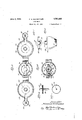
- Fig.l 4 is aside elevation of the floating valve.
- Y I n F ig'. 5 is a bottom plan vievv of Figure 4.
- Fig. 6, is a detail sectional view as taken on 'line 6-6 Figure 1.
- Fig. 7 is a topplan view of Figure 8.
- Fig. 8 isa side elevation, partly broken away, of the yoke likemember for limiting the movement of thefloating valve in one direction.
- the numeral 10 designates generally a mixing chamber having 'an inlet 11, for outtached a tubular extension 12, which latter is held in position in any suitable manner such as by clamping means 13.
- the outlet 14, of the extension 12 communicates with the intake of the engine, and if desired a protecting screen 15, may be employed to prevent foreign particles from being drawn into the engine.
- the screen 15, may be located in any desired or suitable position, and the usual throttle valve 16, may be enz@ ployed.
- a nozzle designated generally by the ret erence numeral 17, is arranged to discharge into the mixing chamber 10, and is preferably arranged entirely Within the casing which forms part of the mixing chamber.
- the nozzle is preferably supported by means of a casting or member 18, having an opening 19, therethrough to receive the tapered portion 20, of the nozzle, the extremity 21, of which portion extends beyond the member 18, and is threaded to receive a nut or collar 22, by means of which latter the nozzle is rcmovably secured in position.
- a passage 23 which extends longitudinally thereof and discharges through the upper end of the nozzle, preferably centrally thereof.
- the portion of the passage adjacent the upper end thereof is enlarged as at 24, and the bottom of the enlarged portion is shaped to form a valve seat 25.
- a floating valve 26, extends into the portion 24, of the passage 23, and cooperates with the seat 25, for shutting off the supply of fluid from a supply tank or chamber 27.
- the valve 25, is held upon its seat by gravity and is provided With a circumferential flange 28, preferably spaced from the upper end 29, of the valve and upon Which ange the suction created in the engine operates to unseat the valve 26, against the Weight of the valve. The extent of the unseating movement of the valve being controlled by the degree of suction in the engine.
- any suitable means may be employed, such as a yoke 30, having a base 81, provided with a threaded opening therethrough to receive the threaded extremity of the nozzle 17,V
- vthe yoke which latter. is provided with external threads to adjustably receive'the yoke 30.
- the top 32, of vthe yoke is provided with a downwardly opening recess .38, adapted tov receive the extremity 29, of the valve 26, and serves as a means for assisting in guiding the valve in its seating and unseating movements.
- the external diameter of the valve 25, is slightly less than the internal diameter of the portion 24, of the passage v23,v so that when the valve is unseat-ed the fluid will flow therearound.
- the supply chamber 27, is provided withan outlet 34, which has communication with the passage28, preferably through the medium Lao , a suitable connection 50, topreheat the con-V of a passage 35, inthe member 18,.and if desired any suitable means may beprovided for controlling the supply of fluid from the chamber 27, to the nozzle 18, such as a sultable valve 36, here-shown as a needle valve construction. f v. c Y
- the chamber 27, receives its supply from any suitable source through the inlet pipe 37, controlled be provided to extend through 'the Chamber 27, out of communication therewith and through which pipe, through a suitable'connection41,theexhaust gases from the engine vmay be passed to preheat thefluid before it is supplied to the nozzle 17; v
- a second supply chamber 42 is provided for-maintaining a supply of fuel, such as gasoline, kerosene, or thelilte, the chamber having an outlet 43, which latter has communication with a passage'44, inthe member18.
- fuel such as gasoline, kerosene, or thelilte
- VThis passage 44 is also provided with a suitable controlling means such as a needle valve 45,' Vwhereby the amount of fuel delivered from the chamber 42, may be controlled.
- The' chamber 42.y is supplied through a pipe4 46, from-any suitable source and is controlled by a suitable valve 47, which valve in turn.
- afloat 48 arrangedfwithin the chamber 42.
- a pipe .49 may beextended through the chamber 42, outk of communication therewith so that the exhaust rgases from' the engine may be delivered thereto through tents of thefchamber.
- Thev passage 44 has
- the passages 51 may extend through the end of thenozzle although this is not necessary.
- a pipeV 40, ⁇ may x 26, isa tip 52, having a chamberl5i3, opening through the lower Vface thereof and a plurality of openings or jet orifices 54, in communication with the chamber 53.
- the tip is adapted'to resta'gainstthe base 31, of the yoke 30, andiencempasses'the 53, has communication'withthe in the nozzle17, .preferably y 1v through the medium v ⁇ of passages oropenings f soi-f.y 55, Vinthe. nozzle A17, so thatfthe'fu'el Whichvis chamber through the open' and 1,1175 of. th.;
- a carburetor includi' g a mixingcham-r ⁇ ber, a nozzle'discharging ⁇ into the chamber,
- said meansV embodying f outlets extending through V,the end of the noz zle,'a floating valve forfcontrolling. one of; said outlets, an -imperforate cement ConnectedA 'la E 75.' 'is if y l Akk ture andk atomization of .thev fuel and flu-id.
- a carburetor including a mixing chamber, a nozzle discharging into the chamber, means for separately supplying two dif- Y ferent fluids to the nozzle, said means embodying outlets extending through the end of the nozzle, a floating valve for controlling one of said outlets, said valve being controlled '15 in its action by engine suction, an imperforate disc like formation connected with the Valve and extending across both of said outlets, said Y disc being disposed between said outlets and the intake of the engine, and against which disc both of the fluids are directed to mix' them, and a cage like structure mounted on said nozzlel and in which case the Valve and disc freely operate.
- a carburetor including a mixing chamber, a nozzle discharging into the chamber,
Landscapes
- Engineering & Computer Science (AREA)
- Chemical & Material Sciences (AREA)
- Combustion & Propulsion (AREA)
- Mechanical Engineering (AREA)
- General Engineering & Computer Science (AREA)
- Nozzles (AREA)
Description
June 3,- 1930. F; H. scHor-:TTLER GARBURETOR Filet; Aug4l5, 1925 2 Sheets-Sheet. l
June 3, 1930. F. H. scHoETTLER 1,761,846
CARBURETOR Filed Aug. l5, 1925 2 SheetsfSheet. 2
A i 2.5 the construction and in the combination and Patented l.lune 3, 193@ 'Aras PATH?? FREDERICK H. SCHOETTLER, OF CHICAGO, ILLINOIS, ASSIGNOB F THIRTY-FIVE PER CENT lIIO JOI-IN H. TAFTQOF CHICAGO, ILLINOIS, AND TNENTY-FIVE PER CENT T0 .WILLIAM.F. BRUG'IVIANN, OF EVANSTON, ILLINOIS i CARBURETOR VApplicationfiled August 15, 1923. Serial No. 657,543.
y 1 YThis'invention relates to improvements in carburetors and one of the objects of the same f 1s to improve and simplify the construction of a carburetor and toprovide improved vmeans for supplying and mixing a fluid, such asrvvater, With the charge of fuel and then deliver the mixture to the engine thereby reducing the fuel consumption and at the same time eliminate the formation of carbon.
A further-object is to provide an improved device ofthis character in Which the supply offluid is controlled by means of a floating valve, the valve beingV actuated inone direction by gravity and being influenced in its operation in the opposite direction by suction created in the engine cylinder.
" A further object is to provide an improved device'of this character which Will be simple, durable, and'v compact in construction and effective and eicient in operation.
- To the attainmentof these ends and the accomplishment of other new and useful objects vaswvill appear, the invention consists' ingthe features vof novelty in substantially arrangement of the several parts as hereinafter more fully described and claimed and as *shown in the accompanying` drawings, in
? side air and an outlet'to which may be atofthe end of the nozzle andinterchangeable tip. v,
Y F 3is a*horizontalsectional vieW as taken on line 3 3 Figure 1.
Fig.l 4, is aside elevation of the floating valve. Y I n F ig'. 5, is a bottom plan vievv of Figure 4. Fig. 6, is a detail sectional view as taken on 'line 6-6 Figure 1.
Fig. 7 is a topplan view of Figure 8.
Fig. 8, isa side elevation, partly broken away, of the yoke likemember for limiting the movement of thefloating valve in one direction.
Referring more Vparticularly* to the drawings the numeral 10, designates generally a mixing chamber having 'an inlet 11, for outtached a tubular extension 12, which latter is held in position in any suitable manner such as by clamping means 13. The outlet 14, of the extension 12, communicates with the intake of the engine, and if desired a protecting screen 15, may be employed to prevent foreign particles from being drawn into the engine. Obviously the screen 15, may be located in any desired or suitable position, and the usual throttle valve 16, may be enz@ ployed.
A nozzle designated generally by the ret erence numeral 17, is arranged to discharge into the mixing chamber 10, and is preferably arranged entirely Within the casing which forms part of the mixing chamber. The nozzle is preferably supported by means of a casting or member 18, having an opening 19, therethrough to receive the tapered portion 20, of the nozzle, the extremity 21, of which portion extends beyond the member 18, and is threaded to receive a nut or collar 22, by means of which latter the nozzle is rcmovably secured in position.
Within the nozzle 17, is a passage 23, which extends longitudinally thereof and discharges through the upper end of the nozzle, preferably centrally thereof. The portion of the passage adjacent the upper end thereof is enlarged as at 24, and the bottom of the enlarged portion is shaped to form a valve seat 25.
A floating valve 26, extends into the portion 24, of the passage 23, and cooperates with the seat 25, for shutting off the supply of fluid from a supply tank or chamber 27. The valve 25, is held upon its seat by gravity and is provided With a circumferential flange 28, preferably spaced from the upper end 29, of the valve and upon Which ange the suction created in the engine operates to unseat the valve 26, against the Weight of the valve. The extent of the unseating movement of the valve being controlled by the degree of suction in the engine.
As a means for limiting the unseating movement of the valve by the suction in the engine, any suitable means may be employed, such as a yoke 30, having a base 81, provided with a threaded opening therethrough to receive the threaded extremity of the nozzle 17,V
which latter. is provided with external threads to adjustably receive'the yoke 30. The top 32, of vthe yoke is provided with a downwardly opening recess .38, adapted tov receive the extremity 29, of the valve 26, and serves as a means for assisting in guiding the valve in its seating and unseating movements. f
The external diameter of the valve 25, is slightly less than the internal diameter of the portion 24, of the passage v23,v so that when the valve is unseat-ed the fluid will flow therearound. By adjusting the yoke 30, "upon the end ofthe nozzle17, itwill be manifest that the extent of movement ofthe valife maybe varied. Y, A .Y
The supply chamber 27, is provided withan outlet 34, which has communication with the passage28, preferably through the medium Lao , a suitable connection 50, topreheat the con-V of a passage 35, inthe member 18,.and if desired any suitable means may beprovided for controlling the supply of fluid from the chamber 27, to the nozzle 18, such as a sultable valve 36, here-shown as a needle valve construction. f v. c Y The chamber 27, receives its supply from any suitable source through the inlet pipe 37, controlled be provided to extend through 'the Chamber 27, out of communication therewith and through which pipe, through a suitable'connection41,theexhaust gases from the engine vmay be passed to preheat thefluid before it is supplied to the nozzle 17; v
A second supply chamber 42,is provided for-maintaining a supply of fuel, such as gasoline, kerosene, or thelilte, the chamber having an outlet 43, which latter has communication with a passage'44, inthe member18.
The' chamber 42.y is supplied through a pipe4 46, from-any suitable source and is controlled by a suitable valve 47, which valve in turn.
is controlled by afloat 48, arrangedfwithin the chamber 42.
Ifv desired a pipe .49, may beextended through the chamber 42, outk of communication therewith so that the exhaust rgases from' the engine may be delivered thereto through tents of thefchamber. Thev passage 44, has
communication with a plurality of passagesV 51, in the nozzle 18, any number of whichV latter passages may be provided to extendl longitudinally ofl the -nozzle and Y encompass the passage 23, aswell as the enlarged p01*-,
tion 24, thereof. If desired the passages 51, may extend through the end of thenozzle although this is not necessary. c
Adjust-ably mounted upon the threadedex-V tremity of the nozzle 17, adjacent the .valve byy a valve 38, which latter isinl turn controlled by a lioat 39. A pipeV 40,` may x 26, isa tip 52, having a chamberl5i3, opening through the lower Vface thereof and a plurality of openings or jet orifices 54, in communication with the chamber 53.
Any number of these orilices54, may be. o l
providedto meet the requirements ofthe engine and the tip is interchangeable to permit of the employment of a tip havingV the desired4 or required number of j et openings or endof the'nozzle as well asfthe'valvefV 26. Thechamber passages 51,
delivered into thechamber 53, in the-tip will bedistributed through thefopenings 54, intof Y the mixingk chamber 10, where -it will-,be ,y mixed with the fluid from the passage 23,k
and also. with the air drawn into the mixing n Y y orifices 5 4. The tip is adapted'to resta'gainstthe base 31, of the yoke 30, andiencempasses'the 53, has communication'withthe in the nozzle17, .preferably y 1v through the medium v`of passages oropenings f soi-f.y 55, Vinthe. nozzle A17, so thatfthe'fu'el Whichvis chamber through the open' and 1,1175 of. th.;
latter.
. Y As ythe suction in drawn from thepassage 23, and mixed with the fuel from the jet openings 54.v Obviously the engine increases the valve 26, willfbe, unseated and fluidwill be the valves 36'v and 45 may bese-adjusted 'orset to obtain-the desired proportions Yof the` iuid and fuel suppliedto the nozzle 17 The suction upon the nozzle is controlled bythe -throttle16 andY during the: operation of the engine air willbedrawn intov the mixv ing chamber 10, through the fopening11',., Y thereof. Asdrawn in, theair will encom'V pass the nozzle as well 'as .the fluid and fuelv deliveredl from the-,nozzle V17to vmix there-v with in the mixing chamberlO, the entire..VVV
mixture being delivered intoithe engine-f By supplying such a mixture to the engine the consumption'vof fuel will be reduced to' af minimum and the eiciency ofthe engine vwill be increased. At the Sametime carbon will be eliminated. n y
lWhile the preferred formof theinvntion has been hereinfshown and described, it is to be' understood that various changesv may be -made in thedetails of construction and in the n combination and arrangement of the several parts within the .scope'of the claims without departing from the spirit'loffthis invention.
- Whatisclaimed as new is: j.
`1. A carburetor includi' g :a mixingcham-r` ber, a nozzle'discharging `into the chamber,
means for separately supplying two diffe-rent fluids to the* nozzle, said meansV embodying f outlets extending through V,the end of the noz zle,'a floating valve forfcontrolling. one of; said outlets, an -imperforate baie ConnectedA 'la E 75.' 'is if y l Akk ture andk atomization of .thev fuel and flu-id.
with the valve and extending across both of said outlets, said baiile being disposed between said outlets and the intake of the engine and against which baiiie both of the uids are directed to mix them, and means mounted upon thenozzle for limiting the movement of the Valve. 2. A carburetor including a mixing chamber, a nozzle discharging into the chamber, means for separately supplying two dif- Y ferent fluids to the nozzle, said means embodying outlets extending through the end of the nozzle, a floating valve for controlling one of said outlets, said valve being controlled '15 in its action by engine suction, an imperforate disc like formation connected with the Valve and extending across both of said outlets, said Y disc being disposed between said outlets and the intake of the engine, and against which disc both of the fluids are directed to mix' them, and a cage like structure mounted on said nozzlel and in which case the Valve and disc freely operate.
3. A carburetor including a mixing chamber, a nozzle discharging into the chamber,
means for separately supplying two different fluids to the nozzle, said means embodying outlets extending through the end of the nozzle, a floating valve for controlling one of said outlets, said valve being controlled in its action by engine suction, a disc like formation connected with the Valve and extending acrossboth of said outlets and against which disc both of the fluids are -directed to mix them, a cage like structure in which the Valve and disc freely operate, and means adjustably mounting said cage upon the nozzle. In testimony whereof I have signed my name to this speciiication, on this 13th day 0 of August, A. D. 1923.
FREDERICK H. SCHOETTLER.
Priority Applications (1)
| Application Number | Priority Date | Filing Date | Title |
|---|---|---|---|
| US657543A US1761846A (en) | 1923-08-15 | 1923-08-15 | Carburetor |
Applications Claiming Priority (1)
| Application Number | Priority Date | Filing Date | Title |
|---|---|---|---|
| US657543A US1761846A (en) | 1923-08-15 | 1923-08-15 | Carburetor |
Publications (1)
| Publication Number | Publication Date |
|---|---|
| US1761846A true US1761846A (en) | 1930-06-03 |
Family
ID=24637623
Family Applications (1)
| Application Number | Title | Priority Date | Filing Date |
|---|---|---|---|
| US657543A Expired - Lifetime US1761846A (en) | 1923-08-15 | 1923-08-15 | Carburetor |
Country Status (1)
| Country | Link |
|---|---|
| US (1) | US1761846A (en) |
-
1923
- 1923-08-15 US US657543A patent/US1761846A/en not_active Expired - Lifetime
Similar Documents
| Publication | Publication Date | Title |
|---|---|---|
| US1839102A (en) | Carburetor | |
| US3182646A (en) | Air-bled coaxial injector | |
| US3347536A (en) | Carburetor | |
| US1761846A (en) | Carburetor | |
| US3233878A (en) | Charge forming apparatus | |
| US1377535A (en) | Cakbttreter | |
| US2207456A (en) | Carburetor structure | |
| US1838675A (en) | Carburetor | |
| US1373550A (en) | Carbureter | |
| US1793554A (en) | Apparatus for control of combustion in internal-combustion engines | |
| US1821012A (en) | Carburetor | |
| US1598624A (en) | Carburetor | |
| US1518572A (en) | Vaporizer and carburetor | |
| US1405777A (en) | Carbureting apparatus | |
| US2220949A (en) | Fuel feeding means for internal combustion engines | |
| US1960993A (en) | Charge forming device | |
| US1567807A (en) | Carburetor | |
| US1281778A (en) | Carbureter for internal-combustion engine. | |
| US1715440A (en) | Auxiliary air valve for internal-combustion engines | |
| US1414035A (en) | Carburetor | |
| US1837338A (en) | Carburetor | |
| US1929193A (en) | Charge forming device | |
| US1525275A (en) | Carburetor | |
| US1722934A (en) | Carburetor | |
| US1412000A (en) | Kerosene carburetor |