US1761836A - Dynamo-electric machine - Google Patents
Dynamo-electric machine Download PDFInfo
- Publication number
- US1761836A US1761836A US271124A US27112428A US1761836A US 1761836 A US1761836 A US 1761836A US 271124 A US271124 A US 271124A US 27112428 A US27112428 A US 27112428A US 1761836 A US1761836 A US 1761836A
- Authority
- US
- United States
- Prior art keywords
- armature
- pole
- horn
- leading
- flux
- Prior art date
- Legal status (The legal status is an assumption and is not a legal conclusion. Google has not performed a legal analysis and makes no representation as to the accuracy of the status listed.)
- Expired - Lifetime
Links
- 238000004804 winding Methods 0.000 description 50
- 230000004907 flux Effects 0.000 description 35
- 229920006395 saturated elastomer Polymers 0.000 description 10
- 239000004020 conductor Substances 0.000 description 6
- 238000003466 welding Methods 0.000 description 5
- 238000010586 diagram Methods 0.000 description 3
- XEEYBQQBJWHFJM-UHFFFAOYSA-N Iron Chemical compound [Fe] XEEYBQQBJWHFJM-UHFFFAOYSA-N 0.000 description 2
- 238000010276 construction Methods 0.000 description 2
- LTMHDMANZUZIPE-PUGKRICDSA-N digoxin Chemical compound C1[C@H](O)[C@H](O)[C@@H](C)O[C@H]1O[C@@H]1[C@@H](C)O[C@@H](O[C@@H]2[C@H](O[C@@H](O[C@@H]3C[C@@H]4[C@]([C@@H]5[C@H]([C@]6(CC[C@@H]([C@@]6(C)[C@H](O)C5)C=5COC(=O)C=5)O)CC4)(C)CC3)C[C@@H]2O)C)C[C@@H]1O LTMHDMANZUZIPE-PUGKRICDSA-N 0.000 description 2
- 230000000694 effects Effects 0.000 description 2
- 238000000034 method Methods 0.000 description 2
- 241001150538 Iria Species 0.000 description 1
- IOYNQIMAUDJVEI-BMVIKAAMSA-N Tepraloxydim Chemical group C1C(=O)C(C(=N/OC\C=C\Cl)/CC)=C(O)CC1C1CCOCC1 IOYNQIMAUDJVEI-BMVIKAAMSA-N 0.000 description 1
- 238000013459 approach Methods 0.000 description 1
- BFPSDSIWYFKGBC-UHFFFAOYSA-N chlorotrianisene Chemical compound C1=CC(OC)=CC=C1C(Cl)=C(C=1C=CC(OC)=CC=1)C1=CC=C(OC)C=C1 BFPSDSIWYFKGBC-UHFFFAOYSA-N 0.000 description 1
- 229910052742 iron Inorganic materials 0.000 description 1
- 239000000696 magnetic material Substances 0.000 description 1
- 230000005389 magnetism Effects 0.000 description 1
- 230000003472 neutralizing effect Effects 0.000 description 1
- 230000000630 rising effect Effects 0.000 description 1
- 230000000087 stabilizing effect Effects 0.000 description 1
Images

Classifications
-
- H—ELECTRICITY
- H02—GENERATION; CONVERSION OR DISTRIBUTION OF ELECTRIC POWER
- H02K—DYNAMO-ELECTRIC MACHINES
- H02K23/00—DC commutator motors or generators having mechanical commutator; Universal AC/DC commutator motors
- H02K23/40—DC commutator motors or generators having mechanical commutator; Universal AC/DC commutator motors characterised by the arrangement of the magnet circuits
- H02K23/42—DC commutator motors or generators having mechanical commutator; Universal AC/DC commutator motors characterised by the arrangement of the magnet circuits having split poles, i.e. zones for varying reluctance by gaps in poles or by poles with different spacing of the air gap
Definitions
- each pole of the dynamo is divided into two parts, one part having a high magnetic reluctance path and the other part having a low magnetic reluctance path, which paths are so proportioned that, under short circuit conditions, the cross flux due to armature rei action will saturate the high magnetic reluctance path of each pole to such an. ex tent that the total flux passing through the armature from pole to pole will be reduced to an amount which is just suiicient to keep the short circuit current circulating .in the armature winding.
- the poles will be divided into two parts by a division extending parallel or approximately parallel to the axis of the armature.
- the part pole at the trailing edge of the pole being so much smaller in cross section than the part pole at the leading edge, and the dynamo otherwise so constructed that, under short circuit conditions, the flux Ain the part pole at the leadingedge will be overwhelmed and driven back by the cross flux due to the armature reaction, while the part pole at the trailing edge will be so saturated that the inter-polar flux will be reduced t0 an amount which is just sutlicient to maintain the short circuit current circulating in the armature windings.
- Figs. 2 and 3 show thepractical methods of forming the pole.
- Figs. 4 and 5 show the pole arranged to have a larger airgap under one horn than under the other for the ypurpose of altering the characteristics of the machine to obtain the eli'ect desired.
- Fig. 6 is a diagram iving the field connections for a welding ynamo according to our invention.
- the pole P1 is provided with two horns T and L, L being the leading pole horn and T the trailing pole horn, the armature moving in the direction of the arrow r.
- B1, B2 are the brushes and the line joining these represents the periphery of the armature vdeveloped out flat.
- the ed es of the polar faces on the horns are esignated Tt--Tg-Lg-Lt.
- the field winding on the pole generates a magneto motive force which is in the direction shown by the small arrows (a). If there were no drop in magneto motive force due to the flux passing through or across the ole this magneto motive force would be uni orm across the olar facesy Tt ⁇ Tg and Iig-Lt and in the diagram of magneto motive forces is represented by the rectangles A. B. P. Y. and M. N. Gr. F. wherein the heights A. B. M. N. etc. represent the value of the magneto motive force due to theeld (hereinafter referred to as the polar magneto motive force).
- the armature When the armature is carrying current it will also set up a magneto motive force, the direction of which is at right angles, electrically, to the polar magneto motive force
- a magneto motive force the direction of which is at right angles, electrically, to the polar magneto motive force
- KL the positive value
- JH the negative value
- the point of zero armature magneto motive force being midway between the brushes, that is, on the .polar axis.
- the armature winding is symmetrical the armature magneto motive force can be represented'by the line joining K and H. That is to say at any point of the armature periphery the magneto motive force will be proportioned to its distance from the zero point 0.
- the value of the armature magnetomotive force will be EG and this will be positive (that is it will oppose the polar magneto motive force at this point).
- the -restricted part of the trailing horn has such a section that a magneto motive force equal to WT1 is taken up in driving the flux f through the high reluctance of this part of the pole, there 1s le'ft a part T1U to drive the flux f across the airgap under Tlf-Tg.
- the airgap under Tlf-Tg is equal to the airgap under Lgf-LtL and has the same area, then the part T1U should be approximately equal to the part RS and under these conditions there will be no effestive flux passin through the armature from pole to pole, but only a cross flux f in each pole. There will therefore be no voltage generated. at the brushes, and this is the short circuit condition.
- the armature and lield magneto motive forces should balance one another at the point Lg the essential condition being that when the brushes are short circuited, the whole of the field magneto motive force and such part of the armature magneto motive force should be taken up in forcing the iux f through the high reluctance part of the pole as will leave a residual part T1U to force the flux f across the'airgap Tt--Tg while the residual ma neto motive force RS should be just sufficient to force the flux f across the airgap Lg--Lz thus leaving no magneto Ino tive force available for driving iiux across the Whole armature from pole to pole, (except such small amount as may be necessary to generate'voltage in the armature to balance the internal losses when the short circuit current is flowing).
- Figs. 2 and 3 show two preferred methods of providing the high reluctance path in the pole.
- Filg. 1 we show, Jfor clearness, a w1de gap g-Lg; in general this would not be required, but the gap may be made as shown in Fig. 2 or in Fig. 3 and it is not necessary to completely open the gap, as this may be closed by a thin bridge C of iron (as shown by the dotted lines 1n Fig. 2) this bridge being so thin that it becomes completely saturated by a very small amount of flux.
- This bridge may be of advantage, in certain cases, in helping to eliminate noise.
- FIGs. 4 and 5 constructions are shown whereby the airgap under one horn is greater or less than the airgap under the other horn, in length; but we may vary the length of the airgap under either horn in any way while keeping the average len h equal under the two horns, or in any ot er way which may be desirable in affecting the shape of the characteristic volt-ampere curve or the commutating properties of the machine.
- poles ma be made as shown in Figs. 2 to 5 we may or constructional purposes make the trailing horn separate from the leading horn and bolt each separately to the yoke thus forming a special kind of split pole construction.
- FIG. 6 a two pole dynamo with connections as adapted for welding purposes.
- the poles P1-P2 lie along the horizontal axis, the north pole P1 being on the left hand side, in which case the inter-polar flux will normally pass .from left to right across the armature.
- the direction of rotation of the armature A is assumed to be counterclockwise as shown -by the arrow, so that the cross magnetisation of the armature tends to make the top half of the armature of north polarity.
- the armature winding (not shown) may rbe oflap, wave or other well known type and the coils will generally be of normal full pitch, but may, for certain purposes, be made of short pitch.
- the poles of the magnet are constructed as described with reference to Figs. l-5, the horizontal central part of the pole shoe face being cut away parallel or approximately parallel to the axis of the armature, so that little or no flux enters the armature through this cut away part.
- the width of this cut away part measured at right angleslto the polar axis may be different for different machines and is determined by the purpose for which the machine is tol be used.
- the cut away part may he symmetrical with the polar axis, or it may be greater on one side of the polar axis than on the other, depending on the effect desired.
- the tleading side of the pole may he defined as that side towards which a. point situated on the periphery of the armature outside of the polar arc, approaches as the armature is rotated and the trailing side may bedetined as that side from which a point situated on the periphery of the armatures outside of the polar arc, recedes as the armature is rotated.
- So tar we have considered only the Hux entering the armature from the poles, hut 'when the machine is working as a dynamo there will he a cross magnetising ell'ect due to the armature cross ampere turns and this will, in a dynamo, oppose the polar flux over that part of the airgap under the leading horn lint-Lg and will assist the polar hux on that part of the airgap which is under the trailing horn 'llt-Tg.
- the poles are (for a welding dynamo) provided with a. series of winding D1D2 and the magnetic reluctance of the trailing horn would be made of a suiliciently high value to be still e'ective for limiting the inter-polar ux with currents, down to about, one fourth of the maximum short circuit current, to allow of regulation of the current to suit various sizes of electrodes.
- en a shunt winding Sl-SZ is also add-- ed to assist the series winding, the machine will give a characteristic voltage ampere curve with a relatively high open circuit voltage, and a drooping characteristic having a definite value for the short circuit current.
- the shunt winding added to the series winding is made of such value, that in the normal wormng of the dynamo for a given voltage the magneto motive torce due to it just balances the magneto motive force due to the belt of conductors under the leading pole tace lag-dit, then the machine will give constant current for all -values of the voltage between the given voltage and zero voltage and further, the no load or open circuit voltage may be less than the working voltage so that there is no risk of damage to the shunt Held on open circuit due to over voltage, such as may occur in certain other types of constant current dynamo.
- the shunt magneto motive force will no longer overwhelm completely the residual armature magneto motive force, but Will do so to a smaller extent (except on short circuit) and will generate the necessary lower voltage while the armature current remains substantially constant.
- the value of the magneto motive force generated by the series windings should be about equal to the armature magneto motive force at the point Lg (Fig. l) and as shown at MN under short circuit conditions.
- the shunt windings S1 Sg should give about the same or a slightly greater magneto motive force than that given by the series windings D1 D2 on short circuit. It should be understood however that we do not limit our to theseproportions of windings which are given only by way of example, but may vary the proportions of the windings or may omit or reverse any of the windings as may be desirable for the purpose in view.
- interpoles l are shown and we find it desirable in some cases to incorporate these in the machine, even although their use may not be necessaryfor commutating purposes, as they 'form a veryready means of adjustin the short circuit current and characteristic curve of the machine merely by shifting the brushes within the commutating zone..
- The also assist in stabilizing the machine by eliminating the current in the short circuited coil under the brush.
- These short circuited coils cut the cross leakage field of the armature and thus generate currents which may be of considerable magnitude, and as these currents produce, or tend to produce, a iux in the armature opposing the main field iuX, they thus tend to make the machine very unstable.
- the inter-poles overcome this by neutralising the effect of the cross leakage field on the short circuited coils thus eliminating the currents which would otherwise be generated thereby.
- our invention is not limited by this condition, and the relative strength of pole and armature magnetisation may be such that either the pole magnetisation or the armature magnetisation is predominant at this point, the essential point being that under short circuit conditions, the vreluctance of the trailing horn must be such that the whole of the field magnetomotive force and a large part of the armature magnetomotive force is taken up lin driving the cross iiuX through this extra reluctance leaving the remainder of the armature magnetomotive force to drive the cross flux through the remaining reluctance of the cross polar circuit, so that there is no effective flux traversing the armature from pole to pole and therefore no voltage is enerated at the brushes.
- our invention is not limited to this, but may be used for any other purpose for which constant current generators are applicable.
- a constant current dynamo comprising.J in combination, an armature, an armature winding on said armature, and at least one pair of poles, each pole having two pole horns, a leading pole horn and a trailino' pole horn, the magnetic reluctance of t e trailing pole horn being so much higher than that of the leading pole horn, that, under short circuit conditions, the iux in the leading horn will be reversed due toy armature reaction while .the trailing horn will be so saturated that the flux thereof will be substantially equal to the iuX in the leading horn, and thereby the inter-polar iux will be reduced to an amount which is just suiiicient to maintain the short circuit current circulating in the armature winding.
- a constant current dynamo comprising, in combination, an armature, an armature windin on said armature, and at least one pair o poles around said armature, each pole having two parts, a trailing part with a high magnetic reluctance path and a leading part with a low magnetic reluctance path, and said parts being spaced diii'erent distances from the armature, so arranged that, under short circuit conditions, cross flux due to armature reaction will reverse the Iiux in the leading part and the trailing part will be so saturated that the iux thereof will be substantially equal to that of the leading part and thereby the total iiux passing through the armature from pole to pole will be reduced to an amount which is just suicient to kee the short circuit current circulating in t e armature winding.
- a constant current dynamo comprising, in combination, an armature, an armature Windin on said armature, and at least one pair o poles around said armature, each pole having two parts, a trailing part with llU a high magnetic reluctance path and a leading part with a low magnetic reluctance path, and said parts having polar faces of diierent areas, so arranged that, under short circuit conditions, cross flux due to armature reaction will reverse the flux in the leading part and the trailing part will be so saturated that the iux thereof will be substantially equal to that of the leading part and thereby the total liux passing through the armaturevfrom pole to pole will be reduced to anamount which 1s just suilicient to keep the short circuit current circulating in the armature winding.
- a constant current dynamo comprising, in combination, an armature, an armature winding on said armature, at least one pair of poles around said armature each -pole having two parts, a trailing part with a high magnetic reluctance path and a leading part with a low magnetic reluctance path, a series winding on said.
- poles and a shunt winding on the poles arranged to assist' the series winding, so arranged that, under short circuit conditions, cross iiux .due to armature reaction reverse the liux in the leading part and the 4 trailing part will be so saturated that the ux thereof will be substantially equal to that of the leading part and thereby the total ux passing through the armature from pole to pole will be reduced to an amount which is just suilicient to keep the short circuit current circulating in the armature winding.
- a constant current dynamo comprising, in combination, an armature, an armature winding on said armature, at least one pair of poles around said armature, each pole having two parts, a trailing part with a high magnetic reluctance'path and a leading part with a low magnetic reluctance path and interpoles, so arranged that, under short circuit conditions, cross hun due to armature reaction will reverse the dun in the leading part and the trailing part he so saturated that the lux thereof will he suhstantially equal to that ci the leading part and thereby the total ux passing through the armature from pole to pole will he rcduced to an amount which is just sucient to keep the short circuit current circulating in the armature winding.
- a constant current dynamo comprising, in combination, an armature having an armature winding thereon, at least one pair of poles around said armature, each pole having two parts, one with a high magnetic reluctance path and the other with a low magnetic reluctance path, a series winding on said poles, a shunt winding on the poles arranged to assist the series winding and interpoles, so arranged that, under short circuit conditions, cross ux due to armature reaction will reverse the flux in the leading part and the trailin part will be so saturated that the flux t ereof will be substantially equal to that of the leading'part and thereby the total flux passing through the armature from pole to pole will be reduced to an amount which is just sufficient to keep the lshort circuit current circulating in the armature winding.
- a constant current dynamo comprising, in combination, an armature, having an armature winding thereon, a pair of poles, each pole4 having two parts, a leading part and trailing part, the leading part being of larger cross sectional area than the other, and a field winding generating flux in said poles, so constructed and arranged that, under short circuit conditions, thelux in the leading part will be reversed due to armature reaction while the trailing part will be e so saturated that the flux thereof will be substantially equal to that of the leading part and thereby the inter-polar iiux will be reduced to an amount which is just suiiicient to maintain the short circuit current circulating in the armature winding.
- a constant current dynamo comprising, in combination, an armature having an armature winding thereon, a pair of poles, each pole having two parts, a leading part and a trailing part, thev trailing part having a parti of greatly reduced cross-sectional area forming a high ma etic reluctance path, interpoles, a held winding on both the poles and interpoles connected inseries with the armature winding, and a shunt winding on the poles only, arranged to assist the series winding thereon, so arranged that, under short circuit conditions, cross ux duc to armature reaction will reverse the ilux produced lo the held winding in the leading part an the trailing part will be so saturated that the dux thereof will be substantially equal to that of the leading part and thereby the inter-polar llux will be reduced to an amount which is just suliicient to keep the short circuit current circulating in the armature Io? aq; .y
- a dynamo of the constant current type comprising, in cornlnination,- an armature, armature conductors on said armature, poles with eld windings thereon, said poles each having two horns, a leading pole horn with i a low magnetic reluctance path and a trailing pole horn with a higli magnetic reluctance path, so proportioned that, when the dynamo is short circuited, the magneto-motive force produced by the armature conductor overwhelms the magneto-motive torce y produced by the eld winding in the leading pole horn and the flux in the trailing pole horn is kept by the reluctance thereof substantially equal to the flux in the leading pole horn, thereby reducing the inter-polar iux to an amount which is just sufficient to keep the short circuit current circulating in the armature winding.
- a dynamo of the constant current type comprising, in combination, an armature, armature conductors on said armature, poles with field windings thereon said oles each having two horns, a leading pole orn with a low reluctance part and a trailing pole horn with a high reluctance part, said horns 10 being so arranged and proportioned that, when the dynamo is short circuited, the magneto-motive force produced by the armature conductors overwhelms the magnetomotive force produced by the field winding in the leading pole horn, the quotient of the difference between the magneto-motive forces in the leading pole horn divided by the reluctance of this horn being substantially equal to the quotient of the sum oit these magneto-motive forces in the trailing pole horn divided by the reluctance of this horn.
Landscapes
- Engineering & Computer Science (AREA)
- Power Engineering (AREA)
- Synchronous Machinery (AREA)
Description
June 3, 1930- J. c. MACFARLANE m AL 1,761,836
DYNAMO ELECTRIC MACHINE Filed April 19. 1928 2 Sheets-Sheet 1 Figa. 2.
June 3, 1930o J. c. MACFARLANE ET AL 1,761,836
DYNAMO ELECTRIC MACHINE Filed April 19, 1928 2 Sheets-Sheet 2 ML WM /YL L Aw Maar/wn fsf/v5,
iria/ways:
Patented June 3, 1930 JAMES COLQUHOUN E AND WILLIAM ALLAN MACFABLANE, OF GLASGOW,
S('}0.|.LAN1I) DYNAMO-ELEGTRIC MACHINE Application led April 19, 1928, Serial No. 271,124, and in Great Britain April 25, 1927.`
,they may be used for any other purpose for which constant current dynamos are normally used.
According to this invention, each pole of the dynamo is divided into two parts, one part having a high magnetic reluctance path and the other part having a low magnetic reluctance path, which paths are so proportioned that, under short circuit conditions, the cross flux due to armature rei action will saturate the high magnetic reluctance path of each pole to such an. ex tent that the total flux passing through the armature from pole to pole will be reduced to an amount which is just suiicient to keep the short circuit current circulating .in the armature winding.
The poles will be divided into two parts by a division extending parallel or approximately parallel to the axis of the armature. the part pole at the trailing edge of the pole being so much smaller in cross section than the part pole at the leading edge, and the dynamo otherwise so constructed that, under short circuit conditions, the flux Ain the part pole at the leadingedge will be overwhelmed and driven back by the cross flux due to the armature reaction, while the part pole at the trailing edge will be so saturated that the inter-polar flux will be reduced t0 an amount which is just sutlicient to maintain the short circuit current circulating in the armature windings.
In order that the invention may be clearly understood and readily carried into practice the same will now be described with reference to the accompanying drawings showing certain explanatory diagrams and practical emv. bodiments, by way of example, wherein followed. It should of course be understood v that the dimensions of the pole shown iry Fig. 1 are exaggerated for the purpose o making quite clear the operation of our invention.
Figs. 2 and 3 show thepractical methods of forming the pole.
Figs. 4 and 5 show the pole arranged to have a larger airgap under one horn than under the other for the ypurpose of altering the characteristics of the machine to obtain the eli'ect desired.
Fig. 6 is a diagram iving the field connections for a welding ynamo according to our invention.
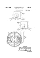
Referring to Fig. 1 the pole P1 is provided with two horns T and L, L being the leading pole horn and T the trailing pole horn, the armature moving in the direction of the arrow r. B1, B2, are the brushes and the line joining these represents the periphery of the armature vdeveloped out flat. convenience of description the ed es of the polar faces on the hornsare esignated Tt--Tg-Lg-Lt.
The field winding on the pole generates a magneto motive force which is in the direction shown by the small arrows (a). If there were no drop in magneto motive force due to the flux passing through or across the ole this magneto motive force would be uni orm across the olar facesy Tt`Tg and Iig-Lt and in the diagram of magneto motive forces is represented by the rectangles A. B. P. Y. and M. N. Gr. F. wherein the heights A. B. M. N. etc. represent the value of the magneto motive force due to theeld (hereinafter referred to as the polar magneto motive force).
When the armature is carrying current it will also set up a magneto motive force, the direction of which is at right angles, electrically, to the polar magneto motive force For A and in the case of a dynamo will have the positive value KL in line with the positive brush and the negative value JH in line with the negative brush, the point of zero armature magneto motive force being midway between the brushes, that is, on the .polar axis. Since the armature winding is symmetrical the armature magneto motive force can be represented'by the line joining K and H. That is to say at any point of the armature periphery the magneto motive force will be proportioned to its distance from the zero point 0. Thus at the leading tip Lt the value of the armature magnetomotive force will be EG and this will be positive (that is it will oppose the polar magneto motive force at this point).
If the windings are so chosen that at the point Lg the polar magneto motive force (represented by MN and having the direction (a)) is made equal to the armature magneto motive force (as represented by NM and having the direction (12)), then over the whole polar face Lg-Lt the armature magneto motive force will overwhelm the polar magneto motive force and will have the mean value RS in excess of the polar magneto motive force SX. This excess of armature magneto motive force over polar magneto motive force will tend to send a flux represented by the chain dotted line f into the pole from the armature over the whole polar face Lg-Lt. In the same way the magneto motive force over the face Tt-Tg will be represented by the sum of the polar and armature magneto motive forces viz.- WV for the polar and VU for the average armature magneto motive force.
If now the -restricted part of the trailing horn has such a section that a magneto motive force equal to WT1 is taken up in driving the flux f through the high reluctance of this part of the pole, there 1s le'ft a part T1U to drive the flux f across the airgap under Tlf-Tg. If the airgap under Tlf-Tg is equal to the airgap under Lgf-LtL and has the same area, then the part T1U should be approximately equal to the part RS and under these conditions there will be no effestive flux passin through the armature from pole to pole, but only a cross flux f in each pole. There will therefore be no voltage generated. at the brushes, and this is the short circuit condition.
It is of course not necessary that the armature and lield magneto motive forces should balance one another at the point Lg the essential condition being that when the brushes are short circuited, the whole of the field magneto motive force and such part of the armature magneto motive force should be taken up in forcing the iux f through the high reluctance part of the pole as will leave a residual part T1U to force the flux f across the'airgap Tt--Tg while the residual ma neto motive force RS should be just sufficient to force the flux f across the airgap Lg--Lz thus leaving no magneto Ino tive force available for driving iiux across the Whole armature from pole to pole, (except such small amount as may be necessary to generate'voltage in the armature to balance the internal losses when the short circuit current is flowing).
The conditions as described above will of course be modified if the airgap under the trailing horn is greater or less than the airgap under the leading horn in len h and/or area, the description given above eing based on equal airgap lengths and equal areas under each horn.
Figs. 2 and 3 show two preferred methods of providing the high reluctance path in the pole. 'Although in Filg. 1 we show, Jfor clearness, a w1de gap g-Lg; in general this would not be required, but the gap may be made as shown in Fig. 2 or in Fig. 3 and it is not necessary to completely open the gap, as this may be closed by a thin bridge C of iron (as shown by the dotted lines 1n Fig. 2) this bridge being so thin that it becomes completely saturated by a very small amount of flux. This bridge may be of advantage, in certain cases, in helping to eliminate noise.
In Figs. 4 and 5 constructions are shown whereby the airgap under one horn is greater or less than the airgap under the other horn, in length; but we may vary the length of the airgap under either horn in any way while keeping the average len h equal under the two horns, or in any ot er way which may be desirable in affecting the shape of the characteristic volt-ampere curve or the commutating properties of the machine.
While the poles ma be made as shown in Figs. 2 to 5 we may or constructional purposes make the trailing horn separate from the leading horn and bolt each separately to the yoke thus forming a special kind of split pole construction.'
As a practical embodiment of this invention, there is shown in Fig. 6 a two pole dynamo with connections as adapted for welding purposes. The poles P1-P2 lie along the horizontal axis, the north pole P1 being on the left hand side, in which case the inter-polar flux will normally pass .from left to right across the armature. The direction of rotation of the armature A is assumed to be counterclockwise as shown -by the arrow, so that the cross magnetisation of the armature tends to make the top half of the armature of north polarity.
The armature winding (not shown) may rbe oflap, wave or other well known type and the coils will generally be of normal full pitch, but may, for certain purposes, be made of short pitch.
The poles of the magnet are constructed as described with reference to Figs. l-5, the horizontal central part of the pole shoe face being cut away parallel or approximately parallel to the axis of the armature, so that little or no flux enters the armature through this cut away part. The width of this cut away part measured at right angleslto the polar axis may be different for different machines and is determined by the purpose for which the machine is tol be used. The cut away part may he symmetrical with the polar axis, or it may be greater on one side of the polar axis than on the other, depending on the effect desired. It will he seen therefore that, on the assumption that there is no armature reaction to modify'the proportions ol lux entering the armature at each side of the pole, the flux from, say, the north pole P1 divides into two parts, one part entering the armature from the pole face Lt-Lg and the other part entering the armature trom the pole face Tft-Tg and the roportion of ux entering the armature rom each side will depend on the relative reluctance of the paths through the two pole parts 'l and L. l'nV the dynamo, the magnetic reluctance ot the path through the part pole 'l is increased by cutting away the magnetic material as already described.
ln order that the terms leading and trailing may he clearly understood, the tleading side of the pole may he defined as that side towards which a. point situated on the periphery of the armature outside of the polar arc, approaches as the armature is rotated and the trailing side may bedetined as that side from which a point situated on the periphery of the armatures outside of the polar arc, recedes as the armature is rotated.
So tar we have considered only the Hux entering the armature from the poles, hut 'when the machine is working as a dynamo there will he a cross magnetising ell'ect due to the armature cross ampere turns and this will, in a dynamo, oppose the polar flux over that part of the airgap under the leading horn lint-Lg and will assist the polar hux on that part of the airgap which is under the trailing horn 'llt-Tg. 'llhis cross magnetising edect of an armature is of course well known and 'is the cause of the distortion of the main held in ordinary dynamos and motors, which leads to sparking at the hrushes and is usually combated by making the held magnetisation relatively strong and the armature magnetisation relatively weak. ln our invention however, we make use of the cross magnetising eiect of the armature as described with reference to Fig. 1.
lt was mentioned in the description with reference to Fig. l that the trailing pole horn must have a very high reluctance, and the value of this reluctance is such that the whole of the eld magneto motive force and a portion of the armature magneto motive force are taken up in forcing a flux, equal in amount to that which enters the pole under the leading horn through the trailing horn. Under the conditions stated, this will be the case when the magneto motive force taken up in forcing this flux through the reluctance of the trailing horn is approximately double the eld magneto motive force. It will he appreciated that since under these conditions, as much flux is returning to the pole on the leading airgap Lg-Lt as is entering the armature on the trailing airgap 'Eg-Tt there will be no ellective flux passing through the armature and therefore no voltage generated. This is the short circuit condition and the control of the short circuit current, with a given machine, depends only on the relative strength of the armature magnetisation and the field magnetisation.
The poles are (for a welding dynamo) provided with a. series of winding D1D2 and the magnetic reluctance of the trailing horn would be made of a suiliciently high value to be still e'ective for limiting the inter-polar ux with currents, down to about, one fourth of the maximum short circuit current, to allow of regulation of the current to suit various sizes of electrodes.
With a series winding only this machine would give a characteristic voltage-ampere curve, starting with a very low voltage (due to residual magnetism) with no current, rising to a maximum voltage determined hy the constants of the machine and falling again to zero voltage on short circuit.
en a shunt winding Sl-SZ is also add-- ed to assist the series winding, the machine will give a characteristic voltage ampere curve with a relatively high open circuit voltage, and a drooping characteristic having a definite value for the short circuit current.
llt, for example, the shunt winding added to the series winding is made of such value, that in the normal wormng of the dynamo for a given voltage the magneto motive torce due to it just balances the magneto motive force due to the belt of conductors under the leading pole tace lag-dit, then the machine will give constant current for all -values of the voltage between the given voltage and zero voltage and further, the no load or open circuit voltage may be less than the working voltage so that there is no risk of damage to the shunt Held on open circuit due to over voltage, such as may occur in certain other types of constant current dynamo. As the voltage falls (owing to the arc becoming shorter, or heing short circuited) the shunt magneto motive force will no longer overwhelm completely the residual armature magneto motive force, but Will do so to a smaller extent (except on short circuit) and will generate the necessary lower voltage while the armature current remains substantially constant.
Further control can be obtained by altering the position of the brushes so that a belt of armature conductors act either with or against the series winding on the poles and the control can be still further accentuated by fitting the machine with interpoles having a suitable pole are, which, in addition to correcting any tendency to spark, can be made to add or subtract part of the interpolar iux to that of the main field, thereby affecting the voltage generated. These interpoles l are provided with a series winding Fl-F2.
For a practical welding generator we find that the value of the magneto motive force generated by the series windings should be about equal to the armature magneto motive force at the point Lg (Fig. l) and as shown at MN under short circuit conditions. When the machine is open circuited, that is, when no current is Howin in the armature the shunt windings S1 Sg should give about the same or a slightly greater magneto motive force than that given by the series windings D1 D2 on short circuit. It should be understood however that we do not limit ourselves to theseproportions of windings which are given only by way of example, but may vary the proportions of the windings or may omit or reverse any of the windings as may be desirable for the purpose in view.
In Fig. 6 interpoles l are shown and we find it desirable in some cases to incorporate these in the machine, even although their use may not be necessaryfor commutating purposes, as they 'form a veryready means of adjustin the short circuit current and characteristic curve of the machine merely by shifting the brushes within the commutating zone.. The also assist in stabilizing the machine by eliminating the current in the short circuited coil under the brush. These short circuited coils cut the cross leakage field of the armature and thus generate currents which may be of considerable magnitude, and as these currents produce, or tend to produce, a iux in the armature opposing the main field iuX, they thus tend to make the machine very unstable. The inter-poles overcome this by neutralising the effect of the cross leakage field on the short circuited coils thus eliminating the currents which would otherwise be generated thereby.
Although for the purpose of description we have assumed that under short circuit conditions the armature magnetomotive force and the pole magnetomotive force balance one another at the point Lg, our invention is not limited by this condition, and the relative strength of pole and armature magnetisation may be such that either the pole magnetisation or the armature magnetisation is predominant at this point, the essential point being that under short circuit conditions, the vreluctance of the trailing horn must be such that the whole of the field magnetomotive force and a large part of the armature magnetomotive force is taken up lin driving the cross iiuX through this extra reluctance leaving the remainder of the armature magnetomotive force to drive the cross flux through the remaining reluctance of the cross polar circuit, so that there is no effective flux traversing the armature from pole to pole and therefore no voltage is enerated at the brushes.
lthough we have described a dynamo particularly applicable for generating current for arc welding, our invention is not limited to this, but may be used for any other purpose for which constant current generators are applicable.
1. A constant current dynamo comprising.J in combination, an armature, an armature winding on said armature, and at least one pair of poles, each pole having two pole horns, a leading pole horn and a trailino' pole horn, the magnetic reluctance of t e trailing pole horn being so much higher than that of the leading pole horn, that, under short circuit conditions, the iux in the leading horn will be reversed due toy armature reaction while .the trailing horn will be so saturated that the flux thereof will be substantially equal to the iuX in the leading horn, and thereby the inter-polar iux will be reduced to an amount which is just suiiicient to maintain the short circuit current circulating in the armature winding.
2. A constant current dynamo comprising, in combination, an armature, an armature windin on said armature, and at least one pair o poles around said armature, each pole having two parts, a trailing part with a high magnetic reluctance path and a leading part with a low magnetic reluctance path, and said parts being spaced diii'erent distances from the armature, so arranged that, under short circuit conditions, cross flux due to armature reaction will reverse the Iiux in the leading part and the trailing part will be so saturated that the iux thereof will be substantially equal to that of the leading part and thereby the total iiux passing through the armature from pole to pole will be reduced to an amount which is just suicient to kee the short circuit current circulating in t e armature winding.
3. A constant current dynamo comprising, in combination, an armature, an armature Windin on said armature, and at least one pair o poles around said armature, each pole having two parts, a trailing part with llU a high magnetic reluctance path and a leading part with a low magnetic reluctance path, and said parts having polar faces of diierent areas, so arranged that, under short circuit conditions, cross flux due to armature reaction will reverse the flux in the leading part and the trailing part will be so saturated that the iux thereof will be substantially equal to that of the leading part and thereby the total liux passing through the armaturevfrom pole to pole will be reduced to anamount which 1s just suilicient to keep the short circuit current circulating in the armature winding. h
4. A constant current dynamo comprising, in combination, an armature, an armature winding on said armature, at least one pair of poles around said armature each -pole having two parts, a trailing part with a high magnetic reluctance path and a leading part with a low magnetic reluctance path, a series winding on said. poles and a shunt winding on the poles arranged to assist' the series winding, so arranged that, under short circuit conditions, cross iiux .due to armature reaction reverse the liux in the leading part and the 4 trailing part will be so saturated that the ux thereof will be substantially equal to that of the leading part and thereby the total ux passing through the armature from pole to pole will be reduced to an amount which is just suilicient to keep the short circuit current circulating in the armature winding.
5. `A constant current dynamo comprising, in combination, an armature, an armature winding on said armature, at least one pair of poles around said armature, each pole having two parts, a trailing part with a high magnetic reluctance'path and a leading part with a low magnetic reluctance path and interpoles, so arranged that, under short circuit conditions, cross hun due to armature reaction will reverse the dun in the leading part and the trailing part he so saturated that the lux thereof will he suhstantially equal to that ci the leading part and thereby the total ux passing through the armature from pole to pole will he rcduced to an amount which is just sucient to keep the short circuit current circulating in the armature winding.
6. A constant current dynamo comprising, in combination, an armature having an armature winding thereon, at least one pair of poles around said armature, each pole having two parts, one with a high magnetic reluctance path and the other with a low magnetic reluctance path, a series winding on said poles, a shunt winding on the poles arranged to assist the series winding and interpoles, so arranged that, under short circuit conditions, cross ux due to armature reaction will reverse the flux in the leading part and the trailin part will be so saturated that the flux t ereof will be substantially equal to that of the leading'part and thereby the total flux passing through the armature from pole to pole will be reduced to an amount which is just sufficient to keep the lshort circuit current circulating in the armature winding.A
7. A constant current dynamo comprising, in combination, an armature, having an armature winding thereon, a pair of poles, each pole4 having two parts, a leading part and trailing part, the leading part being of larger cross sectional area than the other, and a field winding generating flux in said poles, so constructed and arranged that, under short circuit conditions, thelux in the leading part will be reversed due to armature reaction while the trailing part will be e so saturated that the flux thereof will be substantially equal to that of the leading part and thereby the inter-polar iiux will be reduced to an amount which is just suiiicient to maintain the short circuit current circulating in the armature winding.
8. A constant current dynamo comprising, in combination, an armature having an armature winding thereon, a pair of poles, each pole having two parts, a leading part and a trailing part, thev trailing part having a parti of greatly reduced cross-sectional area forming a high ma etic reluctance path, interpoles, a held winding on both the poles and interpoles connected inseries with the armature winding, and a shunt winding on the poles only, arranged to assist the series winding thereon, so arranged that, under short circuit conditions, cross ux duc to armature reaction will reverse the ilux produced lo the held winding in the leading part an the trailing part will be so saturated that the dux thereof will be substantially equal to that of the leading part and thereby the inter-polar llux will be reduced to an amount which is just suliicient to keep the short circuit current circulating in the armature Io? aq; .y
9. A dynamo of the constant current type comprising, in cornlnination,- an armature, armature conductors on said armature, poles with eld windings thereon, said poles each having two horns, a leading pole horn with i a low magnetic reluctance path and a trailing pole horn with a higli magnetic reluctance path, so proportioned that, when the dynamo is short circuited, the magneto-motive force produced by the armature conductor overwhelms the magneto-motive torce y produced by the eld winding in the leading pole horn and the flux in the trailing pole horn is kept by the reluctance thereof substantially equal to the flux in the leading pole horn, thereby reducing the inter-polar iux to an amount which is just sufficient to keep the short circuit current circulating in the armature winding.
10. A dynamo of the constant current type comprising, in combination, an armature, armature conductors on said armature, poles with field windings thereon said oles each having two horns, a leading pole orn with a low reluctance part and a trailing pole horn with a high reluctance part, said horns 10 being so arranged and proportioned that, when the dynamo is short circuited, the magneto-motive force produced by the armature conductors overwhelms the magnetomotive force produced by the field winding in the leading pole horn, the quotient of the difference between the magneto-motive forces in the leading pole horn divided by the reluctance of this horn being substantially equal to the quotient of the sum oit these magneto-motive forces in the trailing pole horn divided by the reluctance of this horn. l
In testimony'whereof we aix our signatures., JAMES COLQUHUN MACFRlAN.
WILLIAM ALLAN MCFPJANE.
Applications Claiming Priority (1)
| Application Number | Priority Date | Filing Date | Title |
|---|---|---|---|
| GB1761836X | 1927-04-25 |
Publications (1)
| Publication Number | Publication Date |
|---|---|
| US1761836A true US1761836A (en) | 1930-06-03 |
Family
ID=10890066
Family Applications (1)
| Application Number | Title | Priority Date | Filing Date |
|---|---|---|---|
| US271124A Expired - Lifetime US1761836A (en) | 1927-04-25 | 1928-04-19 | Dynamo-electric machine |
Country Status (1)
| Country | Link |
|---|---|
| US (1) | US1761836A (en) |
Cited By (6)
| Publication number | Priority date | Publication date | Assignee | Title |
|---|---|---|---|---|
| US3068373A (en) * | 1959-06-22 | 1962-12-11 | Genisco Inc | Synchronous motors of the hysteresis type |
| US4438362A (en) | 1982-08-19 | 1984-03-20 | Rotron, Incorporated | Self-starting, direct current motor with permanent magnets of varied magnetic strength |
| US5260620A (en) * | 1992-03-09 | 1993-11-09 | Morrill Giles W | Asynchronous induction motor |
| US5331245A (en) * | 1986-01-13 | 1994-07-19 | Papst Licensing Gmbh | Permanent magnet excited electric motor with improved torque ripple |
| US6940205B1 (en) * | 1997-09-08 | 2005-09-06 | Matsushita Electric Industrial Co., Ltd. | Permanent magnet synchronous motor |
| US20210211016A1 (en) * | 2020-12-31 | 2021-07-08 | Hunan University Of Science And Technology | Denoising optimization method for ac traction motor by chamfering stator tooth shoulder |
-
1928
- 1928-04-19 US US271124A patent/US1761836A/en not_active Expired - Lifetime
Cited By (13)
| Publication number | Priority date | Publication date | Assignee | Title |
|---|---|---|---|---|
| US3068373A (en) * | 1959-06-22 | 1962-12-11 | Genisco Inc | Synchronous motors of the hysteresis type |
| US4438362A (en) | 1982-08-19 | 1984-03-20 | Rotron, Incorporated | Self-starting, direct current motor with permanent magnets of varied magnetic strength |
| US5331245A (en) * | 1986-01-13 | 1994-07-19 | Papst Licensing Gmbh | Permanent magnet excited electric motor with improved torque ripple |
| US5260620A (en) * | 1992-03-09 | 1993-11-09 | Morrill Giles W | Asynchronous induction motor |
| US7233092B2 (en) | 1997-09-08 | 2007-06-19 | Matsushita Electric Industrial Co., Ltd. | Permanent magnet synchronous motor |
| US20050225194A1 (en) * | 1997-09-08 | 2005-10-13 | Hiroshi Murakami | Permanent magnet synchronous motor |
| US6940205B1 (en) * | 1997-09-08 | 2005-09-06 | Matsushita Electric Industrial Co., Ltd. | Permanent magnet synchronous motor |
| US20070205687A1 (en) * | 1997-09-08 | 2007-09-06 | Hiroshi Murakami | Permanent magnet synchronous motor |
| US20070205688A1 (en) * | 1997-09-08 | 2007-09-06 | Hiroshi Murakami | Permanent magnet synchronous motor |
| US7408279B2 (en) | 1997-09-08 | 2008-08-05 | Matsushita Electric Industrial Co., Ltd. | Permanent magnet synchronous motor including permanent magnet with tapered outer edges |
| US7411329B2 (en) | 1997-09-08 | 2008-08-12 | Matsushita Electric Industrial Co., Ltd. | Permanent magnet synchronous motor including permanent magnet with tapered outer edges and rotor core with opening |
| US20210211016A1 (en) * | 2020-12-31 | 2021-07-08 | Hunan University Of Science And Technology | Denoising optimization method for ac traction motor by chamfering stator tooth shoulder |
| US11799353B2 (en) * | 2020-12-31 | 2023-10-24 | Hunan University Of Science And Technology | Denoising optimization method for AC traction motor by chamfering stator tooth shoulder with inscribed arc |
Similar Documents
| Publication | Publication Date | Title |
|---|---|---|
| US1761836A (en) | Dynamo-electric machine | |
| US1910473A (en) | Electrical apparatus and method | |
| US794998A (en) | Dynamo-electric machine. | |
| US608309A (en) | Regulating dynamo-electric machines | |
| US2073526A (en) | Dynamo-electric machine | |
| US2184766A (en) | Cross-field generator | |
| US2666886A (en) | Control of the hysteresis spread of rotating direct current machines | |
| US835363A (en) | Constant-current generator. | |
| US1377074A (en) | Self-regulating dynamo-electric machine | |
| US656127A (en) | Dynamo-electric machine. | |
| US1307099A (en) | of acton vale | |
| US1659106A (en) | Dynamo-electric machine | |
| US643066A (en) | Alternating-current motor. | |
| US1091614A (en) | Dynamo-electric machine. | |
| US424734A (en) | Island | |
| US555191A (en) | Electric motor | |
| US1183006A (en) | Variable-speed generator. | |
| US516553A (en) | sa yers | |
| US656128A (en) | Method of regulating dynamo-electric machines. | |
| US1115724A (en) | Dynamo-electric machine. | |
| US1108087A (en) | Dynamo. | |
| US919604A (en) | Dynamo-electric machine. | |
| US835227A (en) | Dynamo-electric machine. | |
| US511375A (en) | Method of and means for compounding dynamo-electric machines | |
| US428732A (en) | Electric motor and generator |