US1761821A - Self-closing valve - Google Patents
Self-closing valve Download PDFInfo
- Publication number
- US1761821A US1761821A US203432A US20343227A US1761821A US 1761821 A US1761821 A US 1761821A US 203432 A US203432 A US 203432A US 20343227 A US20343227 A US 20343227A US 1761821 A US1761821 A US 1761821A
- Authority
- US
- United States
- Prior art keywords
- valve
- seat
- casing
- self
- handle
- Prior art date
- Legal status (The legal status is an assumption and is not a legal conclusion. Google has not performed a legal analysis and makes no representation as to the accuracy of the status listed.)
- Expired - Lifetime
Links
- 239000002184 metal Substances 0.000 description 8
- 239000007799 cork Substances 0.000 description 6
- 229910000679 solder Inorganic materials 0.000 description 6
- 239000007788 liquid Substances 0.000 description 5
- 241000239290 Araneae Species 0.000 description 2
- 238000010276 construction Methods 0.000 description 2
- 241000905957 Channa melasoma Species 0.000 description 1
- RUPBZQFQVRMKDG-UHFFFAOYSA-M Didecyldimethylammonium chloride Chemical compound [Cl-].CCCCCCCCCC[N+](C)(C)CCCCCCCCCC RUPBZQFQVRMKDG-UHFFFAOYSA-M 0.000 description 1
- 102100033740 Tenomodulin Human genes 0.000 description 1
- 101710114852 Tenomodulin Proteins 0.000 description 1
- 241000382509 Vania Species 0.000 description 1
- 238000004140 cleaning Methods 0.000 description 1
- 238000001914 filtration Methods 0.000 description 1
- 239000000155 melt Substances 0.000 description 1
- 230000008018 melting Effects 0.000 description 1
- 238000002844 melting Methods 0.000 description 1
- 210000004914 menses Anatomy 0.000 description 1
- 238000005192 partition Methods 0.000 description 1
- XXPDBLUZJRXNNZ-UHFFFAOYSA-N promethazine hydrochloride Chemical compound Cl.C1=CC=C2N(CC(C)N(C)C)C3=CC=CC=C3SC2=C1 XXPDBLUZJRXNNZ-UHFFFAOYSA-N 0.000 description 1
- 230000000717 retained effect Effects 0.000 description 1
- 230000035939 shock Effects 0.000 description 1
Images

Classifications
-
- F—MECHANICAL ENGINEERING; LIGHTING; HEATING; WEAPONS; BLASTING
- F16—ENGINEERING ELEMENTS AND UNITS; GENERAL MEASURES FOR PRODUCING AND MAINTAINING EFFECTIVE FUNCTIONING OF MACHINES OR INSTALLATIONS; THERMAL INSULATION IN GENERAL
- F16K—VALVES; TAPS; COCKS; ACTUATING-FLOATS; DEVICES FOR VENTING OR AERATING
- F16K21/00—Fluid-delivery valves, e.g. self-closing valves
- F16K21/04—Self-closing valves, i.e. closing automatically after operation
- F16K21/14—Self-closing valves, i.e. closing automatically after operation with special means for preventing the self-closing
-
- Y—GENERAL TAGGING OF NEW TECHNOLOGICAL DEVELOPMENTS; GENERAL TAGGING OF CROSS-SECTIONAL TECHNOLOGIES SPANNING OVER SEVERAL SECTIONS OF THE IPC; TECHNICAL SUBJECTS COVERED BY FORMER USPC CROSS-REFERENCE ART COLLECTIONS [XRACs] AND DIGESTS
- Y10—TECHNICAL SUBJECTS COVERED BY FORMER USPC
- Y10T—TECHNICAL SUBJECTS COVERED BY FORMER US CLASSIFICATION
- Y10T137/00—Fluid handling
- Y10T137/1624—Destructible or deformable element controlled
- Y10T137/1797—Heat destructible or fusible
- Y10T137/1819—Safety cut-off
-
- Y—GENERAL TAGGING OF NEW TECHNOLOGICAL DEVELOPMENTS; GENERAL TAGGING OF CROSS-SECTIONAL TECHNOLOGIES SPANNING OVER SEVERAL SECTIONS OF THE IPC; TECHNICAL SUBJECTS COVERED BY FORMER USPC CROSS-REFERENCE ART COLLECTIONS [XRACs] AND DIGESTS
- Y10—TECHNICAL SUBJECTS COVERED BY FORMER USPC
- Y10T—TECHNICAL SUBJECTS COVERED BY FORMER US CLASSIFICATION
- Y10T137/00—Fluid handling
- Y10T137/794—With means for separating solid material from the fluid
- Y10T137/8085—Hollow strainer, fluid inlet and outlet perpendicular to each other
Landscapes
- Engineering & Computer Science (AREA)
- General Engineering & Computer Science (AREA)
- Mechanical Engineering (AREA)
- Safety Valves (AREA)
Description
SELF CLOSING VALVE Filed July 5, 1927 3 Sheets-Sheet I l 51 2,2 24 4 5/, g: Q L
A'II'TORNEY June 3, 1930. c. D. FAGAN I SELF CLOSING VALVE 5 Sheets-Sheet 2 Filed July 5. 1927 IQITOR 7 44 ATTORNEY June 1930. I c. D. FAGAN 1 1,761,321
SELF CLOSING VALVE- Filed July 5, 1927 s Sheets-Sheet a INVENTOR BY I ' ATTORNEY Patented June 3, 1930 UNITED, STATES ZPATFENT; orrlci-z CHARLES D. FAGAN, OF SHARON, PENNSYLVANIA, ASSIGNOR TOSHARPSVILLE BOILER WORKS (30., OF- SHARPSVILLE, PENNSYLVANIA, A CORPORATION 01' PENNSYL- VANIA Application filed July 5,
easily tripped to permit self closing. It is' also constructed with a fusible stop block adapted to release the valve when a predetermined temperature is reached in case of a flash back or fire.
Another feature of the present invention resides in the arran ement of a strainer or filter relative to t e valve structure so that effective filtering is accomplished without substantial reduction in the flow of liquid through the valve.
to f
Still further features of-the present invention reside in a cork cushioned valve head and in the relation of the guides thereor, which insure positive and correct seating of the valve and prevent binding of the parts during eratiom It is realize that the present invention .may be embodied-in structures other than those disclosed herewith and therefore, the. disclosure is to be understood as illustrative and not in the limiting sense.
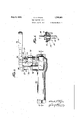
Fig. 1 is an elevational view of the out-- side of one form of the valve.
Fig. 2 is a sectional view taken on line 2-'-2 of 'Fig. 1, showing the valve parts. in"
section.
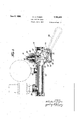
Fig. 3 is an elevational view of the modified form of valve. casing embodying the same valvestructure as shown in Fig.1.
Fig. 4 is a sectional view taken on line 4-4 of Fig. 3 and looking in the direction of the arrows; Fig 5 is a detail view of the valve memr. q Referring now to the drawings and more I especially to Figs. .1 'and 2, the valve casing 1 is provided with an inlet conduit 2 which leads into a hollow cylindrical screen 4 1 4 that is carried by a frame-work 5 integral conditions. The struc- SELF-CLOSING VALVE 1927. Serial IN'O. 208,432.
with a cap nut 6 which is screw threaded into the casing 1. This cylindrical screen I 4 comprises a partition between the inlet conduit 2 and the valve chamber 7, which surrounds the cylindrical screen and leads to the valve proper. The lower part of the frame work 5 isprovided with a seat 8 that seats in a cylindrical openin formed in the casing 1 around the inner en of the inlet 2. This arrangement provides a very strong, positive construction which enables the screen 5 to function fully and does not impede the flow of li uid through'the device in view of the fact t at the total area of the openings in the screen is such .as to substantially equal the area of the o ning in the inlet conduit, and the valve 0 amber 7 is of suflicient size ltoj likewise allow free fiow of liquid in all radial directions from the sides of the screen. The mounting of the screen in the frame may be done in various ways. It may be retained merely by friction, so that the screen may be easil taken out and cleaned or where desired, it may be soldered to the frame. The cap nut arrangement and the seat at the bottom of the frame facilitate removal of the screen for cleaning and also prevents leakage of liquid around the screen ,so that all of the liquid passing through the valve casing must pass through the screen.
-A valve seat 9 is provided in the casing 1 preferably with the axis of the valve seat substantially parallel to'the axis of the cylindrical screen 4. A valve head shown 1n detail in Fig. 5 is mounted to cooperate with the valve seat and comprises an up r guide stem 10 carrying a metal disk 11 w ich supports a cork disk 12 against a metal valve 14 adapted to seat upon the valve seat 9. A guiding spider 15 is mounted ad'acent-the metal valve and is provided wit guiding fingers adapted to guide the valve in its movement. An operating stem 16 extends beneath the guide stem 10 and carries the metal valve 14 and the cork disk 12 in such manner as to allow a slight freedom of movement to the metal valve 14 so that this valve 14 may yield slightlyvtoallow the cork disk to be effective as a cushion. The guide ste'mlO loosely fits a guide opening 17 in the cap nut 18 to ermit a'reciprocatmg.movement of'theguide stem in the opening 17. The cap nut is provided with a' recess 19 to receive a coil spring 20 which bears upon the metal disk 11 on t e guide stem 10, thereby tending .to seat the metal valve 14 onthe valve seat 9. It will be' observed that this construction is such that the. axis of the.
spring is coincident with the axis of the valve. The valve is accurately guided at the upper end by the guide stem 10 reciproeating in the guide openin 17 and at the lower end b the fingers oft e spider 15 0011-. tacting wit the sides of. the o e casing below the valve seat, so always strikesthe seat accuratelyand, the cork cushion absorbs the shock as well as ap lying uniform pressure over the valve to ho d it closed. The lower end 21 of the operating stem 16 is semi-spherical and coo crates with a curved operating arm 2 mounted upon a squared head on an operatconnection 26 in such manner as to i This temperature'is above climatic temperature and is safely below -ifiition point of gasoline va ors. This loc g lug'has a recessed 100 'ng face 32 adapted tocontact with a locking .post 34 screw threaded into the casing 1 and locked in position bya lock nut 35.
n will be observed that bglnmanipulating the handle 28 so that the loc g lug 31 will pass the upper end of,the locking post 34,
I the handle may be swung to rotatethe operatmg'shaft 24 whereby the'operating arm- 22-bearing upon the seml-spherical lower end 21 of the operating stem 16 forces the valve vopen and compresses the coil spring-20. The
handle is then rotated on the pivot 29' to bring the locln'ng lug 31 back of the locking st 34 'and rotative p iessure on the locking lug 31 tightly against the end of the locking post 30, "thereby lockingthe valve case of a flare back or fire the solder melts, thereb freeing the lug 31 from the surface an allowing the'spring 20 to snap the m the t att evalveby means of fusible solder havirig an e. 1s released. The coil spring'through the connected parts just described, forces. the.
the va ve..-casing thereb jrai the locking lug 31 above'thd, st and t hg spring '20 snaps the valve 0 osed. Also in" menses valve closed. D this closing operation the valve is accurate dy described by the gui der 15 so that the metal valve 14 pressed down by the cork disk accuratel seats on lene or gasolene vapors. When the valve is .open, the li uid passing through thevalve may go out t rough the outlet opening 36 in the casing 1. The axes of the outlet openin 36 and the inlet of the conduit 2 are align so that when the valve is in place, the pipe line s stem may be in a straig t line.
Re erring now to Figs. 3 and 4, the valve and operating mechamsm is substantially identical with that just described and the same reference characters have been ap lied thereto so that a separate description 0 the valve disclosed in these figures is unnecessar In the form disclosed in Figs 3 and 4, t e screen is omitted and the valve casing on the outlet side is extended to comprise a manifold 37, which is provided with an outlet 38 adapted to carry t:(pressure gage and a second outlet 39 adap to carry a safety valve. This manifold type of casingis par ticularly desirable for use in connection with T gasolene service stations where the valve is installed on an air pressure line, which requires a safety gageand a safety valve.
The present type of valve is quick acting and positive in its 0 oration and 'at the same time ca ble ofbemg fully o ned with a "relative y small movement 0 the handle,
and automaticall closes in case of -flareback or fire whic may endanger the liquid or vapors normally passed by the valve.
guided as previousl e stem 10 and the SP1;
Having described my invention, I claim:
1. A valve comprising a. casing provided with a pair of openings, a screen member work, 'a screen .supported substantially throughout its len h by said frame, said casing being provi ed with a valve chamber beneath said openings avalve adapted to screw be. seated upon theva ve seat, a cap adapted to close the opening over said valve seat, and means tooperate said valve.
seat beneath oneof said. openings and a 2. A self'closing valve for gasoline serv- 5 ve seat, a valve adap 'ice stations-comprising a valve casing ro- 'vided with a va tedto cooperate with said seat to close the passage.
- for servlce station operations, a stop carried where be engaged and disengaged at the will of the throughtlie valve casing, a spring normally A tendin to seat said valve 'on said valve seat,
manua y operable means to open said valve bysaid valve casing and adapted to cooperate with a stop b ock to hold said valve open,a 'st-op' block secured to said manual means by low temperature fusible solder operator. v 3. A 'self closing valve comprising a casing provided with a passageway and a valve- I .seat'in said passageway, a valve adapted to way, spring means, normally tending operators; one of sai set on said valve seat and close said passageto seat said valve,- memberagainSt said v ve seat manually operable means for opening said valve, said manually o erable means comprising a'rotatable sha and a handle pivoted upon said shaft with the axis of the Y pivot atright angles to the axis ofthe shaft,
and stop means or holding said valve open, said stop means comprising astop member carried by said casing and 'a second stop member upon said pivoted handle, said handle being oscillatable on said pivot to bring said stop meansand said stop'member into and out of operative relation 'to each other.
4. A self closing valve comprising a casing having a passageway therethrough and" a valve seat in said passageway, a valve adapted to set on sa1d seat to close the passageway, a spring normally acting to seat said valve upon said valve seat, manu ally operable means to raise said valve from 1 saldseat against the act on of said sprin and a pair of stop members adapted to Ice maximum atmospherid temperature and be: low the ignition temperature of gasoline vapors, whereby melting of the solder releases the stop, block and'thus initiates closing'of the valve, and manually operated means to render said locking .means effective or ineffective at the will of the operator.
6. A self closing valve comprising a casing provided with a valve seat; a valve head adapted to .engage said seat; spring means operative to bias said valve head into closed position; a rotatable element operative to open the valve against the action of the spring; and a handle attached to-said rotatable element for manually rotating the same, said handle being pivoted to ermit a rocking motion on an axls perpendicular to the axisof saidrotatable element and said handle and valve casin comprising inter locking portions'adapte to be brought into engagement by rocking the handle to lock the valve in its open position. I 7. A self closing valve comprisin a casing provided with a valve seat; a va ve head same, said handle being pivoted to adapted to engage said seat; s ring means operative to bias said valve hea into closed position; a rotatable element operative to en the valve against the action ofthe spring; and a handle attached to said rotatab eelement for manually rotating th:
a rocking motion on an axis perpen icular to the axis of said rotatable element and saidhandle and valve casin comprising interlocking portions ada te to be brought into engagement by r 'ng the handle to .lock the valve in open posit1on,.at least one of. said interlockm g means being designed to fail at a predetermined temperature where'- bythe valve 'is released and closes automatically'when the predetermined temperature is reached.
i CHAS. D. FAGEN.
said valve in raised position from said seat, and means whereby said stop" members may 3 be engaged and disengaged at the will of the anchore whereb" ."an' abnormally high temperature will 0 act the release of the stop member and thus initiate closing of the valve.
5. A self closin valve comprising a cass'topfmembrs being by low temperature fusible solder' ing provided wit a valve seat; a valve head adapted to engage said"seat;' s ring meansoperative to has said valve hea into closed position; means manuall operable to open the valve against fthe action of said springmeans; loclnng means to. lock said manually operable means in position to retain said valve open, said locking meanse' comprising a stop detent means, by solder fusiblelat a temperature above the block adapted to e a the stop block being se t a ur i
Priority Applications (1)
| Application Number | Priority Date | Filing Date | Title |
|---|---|---|---|
| US203432A US1761821A (en) | 1927-07-05 | 1927-07-05 | Self-closing valve |
Applications Claiming Priority (1)
| Application Number | Priority Date | Filing Date | Title |
|---|---|---|---|
| US203432A US1761821A (en) | 1927-07-05 | 1927-07-05 | Self-closing valve |
Publications (1)
| Publication Number | Publication Date |
|---|---|
| US1761821A true US1761821A (en) | 1930-06-03 |
Family
ID=22753987
Family Applications (1)
| Application Number | Title | Priority Date | Filing Date |
|---|---|---|---|
| US203432A Expired - Lifetime US1761821A (en) | 1927-07-05 | 1927-07-05 | Self-closing valve |
Country Status (1)
| Country | Link |
|---|---|
| US (1) | US1761821A (en) |
-
1927
- 1927-07-05 US US203432A patent/US1761821A/en not_active Expired - Lifetime
Similar Documents
| Publication | Publication Date | Title |
|---|---|---|
| US2898926A (en) | Safety disconnect valve | |
| US2181523A (en) | Shut-off valve | |
| US1970726A (en) | Valve | |
| US1761821A (en) | Self-closing valve | |
| US2035762A (en) | Gas cock | |
| US2681736A (en) | Duplex strainer | |
| US2623726A (en) | Valve seat | |
| US2022430A (en) | Valve and float | |
| US1669119A (en) | Valve structure | |
| US1763802A (en) | Thermostat | |
| US1964835A (en) | Valve | |
| US1752048A (en) | Air-service station | |
| US2346223A (en) | Self-closing valve for single directional fluid flow | |
| US2332380A (en) | Fire check | |
| US3202166A (en) | Shut-off valve assembly having a removable plug | |
| US1404103A (en) | Valve | |
| US1925958A (en) | Valve | |
| US2447207A (en) | Fluid control valve | |
| US2753891A (en) | Mixing valve | |
| US2610511A (en) | Valve actuator | |
| US2241920A (en) | Automatic closing atomizer casing | |
| US1774395A (en) | Gas cut-off | |
| US2166304A (en) | Valve-operating mechanism | |
| US2838104A (en) | Fuel oil burner safety device | |
| US2028726A (en) | Trip cock device |