US1761819A - Exhausting mechanism - Google Patents
Exhausting mechanism Download PDFInfo
- Publication number
- US1761819A US1761819A US271635A US27163528A US1761819A US 1761819 A US1761819 A US 1761819A US 271635 A US271635 A US 271635A US 27163528 A US27163528 A US 27163528A US 1761819 A US1761819 A US 1761819A
- Authority
- US
- United States
- Prior art keywords
- tank
- water
- pipe
- inlet
- outlet
- Prior art date
- Legal status (The legal status is an assumption and is not a legal conclusion. Google has not performed a legal analysis and makes no representation as to the accuracy of the status listed.)
- Expired - Lifetime
Links
- 230000007246 mechanism Effects 0.000 title description 23
- XLYOFNOQVPJJNP-UHFFFAOYSA-N water Substances O XLYOFNOQVPJJNP-UHFFFAOYSA-N 0.000 description 66
- 239000007789 gas Substances 0.000 description 15
- 239000012530 fluid Substances 0.000 description 11
- 238000010438 heat treatment Methods 0.000 description 10
- 239000007788 liquid Substances 0.000 description 8
- 238000007599 discharging Methods 0.000 description 3
- 208000002874 Acne Vulgaris Diseases 0.000 description 1
- 238000009825 accumulation Methods 0.000 description 1
- 206010000496 acne Diseases 0.000 description 1
- 238000005266 casting Methods 0.000 description 1
- 230000008878 coupling Effects 0.000 description 1
- 238000010168 coupling process Methods 0.000 description 1
- 238000005859 coupling reaction Methods 0.000 description 1
- 238000003780 insertion Methods 0.000 description 1
- 230000037431 insertion Effects 0.000 description 1
- 239000002184 metal Substances 0.000 description 1
- 238000005065 mining Methods 0.000 description 1
- 230000004048 modification Effects 0.000 description 1
- 238000012986 modification Methods 0.000 description 1
- 108010085990 projectin Proteins 0.000 description 1
Images

Classifications
-
- F—MECHANICAL ENGINEERING; LIGHTING; HEATING; WEAPONS; BLASTING
- F24—HEATING; RANGES; VENTILATING
- F24D—DOMESTIC- OR SPACE-HEATING SYSTEMS, e.g. CENTRAL HEATING SYSTEMS; DOMESTIC HOT-WATER SUPPLY SYSTEMS; ELEMENTS OR COMPONENTS THEREFOR
- F24D19/00—Details
- F24D19/08—Arrangements for drainage, venting or aerating
- F24D19/081—Arrangements for drainage, venting or aerating for steam heating systems
Definitions
- This invention relates to an improved exhausting mechanism, particularly adapted for removing air from the return pipe or air line of a steam heating system, in order to lower the pressure within the system.
- One object of the invention is to provide a simple and compact exhausting unit, suitable for use withhome heating systems.
- Another object is to provide a relatively noiseless exhausting mechanism.
- Another object is to provide an exhausting' mechanism adapted to withdraw gases only from the heating system, combined with connecting mechanism whereby the discharge of water from the heating system into the exhauster is avoided.
- Another object is to provide an exhauster comprising an ejector, a hurling circuit for forcing water through the' ejector, a selfcontained water supply, and connections whereby the hurling circuit cannot lose its prime once the exhauster has been supplied with a suitable quantity of water.
- Another object is to reduce to a minimum the water-friction in the hurling circuit.
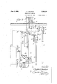
- F ig. 1 is a side elevation, partly in section, of the assembled exhausting mechanism.
- Fig. 2 is a partial elevation and partial vertical 'section of the mechanism shown in Fig. l, the view being taken ⁇ 'substantially onthe line 2-2 of Fig. 1.
- Fig. 3 is a diagrammatic elevation of a portion of a vacuum steam heating system, for use in which this exhausting mechanis'm is especially designed.
- Fig. 4 is a partial vertical section, similar to Fg. 2, showing a modification.
- the improved exhaustng mechansim which forms the particular subject-matter of this invention' is designed to withdraw gascs only from a heating system of the type disclosed for example in Fig. 3 of the atent to Dunhan '1,6l-l,114, granted Octo er 4', 1927.
- a similar system isdisclosed diagrammatically in Fig. 3 of the present drawings,
- the steam generator A maybe of any desired form, and is heated by an automatv ically controlled mechanism so as to vary the heat applied to the boiler in accordance 80 with temperature conditions and thus regulate the sub-atmospheric pressure of the steam delivered to the radiators.
- Steam passes from the' boiler A through supply main B, riser 1 and inlet valve 2 to the ra diator D. It is to be understood that 'any desired number of radiators may be similarly supplied from' the main'B.
- Each inlet valve 2 will normally be open when the radiator is in service to 'permit free passage of steam from the supply main.
- the thermostatic trap E normally retains the steam within the radiator but permits the outflow of accumulated 'liquid condensate and air into the return main F.
- the control mechanism J functions to maintain a :substantially constant difference in pressure between the supply main B (and radiators D) and the return main F.
- An equalizingconnection consisting of the ver: tical pipes 13 and 14'and the horizontal pipe 15 connects ther'eturn main F with the supply main B, a one-way check-valve 16 opening toward the supply main B being' positioned in the horizontal pipe 15. This check-valve will normally remain closed'as long as the pressure in the supply main is higher than the pressure in the return main'.
- a pair of surge chambers 17 and 18 located in pipe 15 at either side of check valve 16, are connected by pipes 19 and 20 with the low and high pressure chambers of a difl'erential controller 21.
- This diflerential controller operates in a well known maImer (as described more in detail in the Dunham patent above referred to) to close an electrc switch 22 when thepressure difl'erential between the supply and return mains falls below a desired minimum, and to open this switch when the desired pressure difi'erential has been attained.
- Switch 22 controls the drivins motor 23 of the exhausting mechanism H, hereinafter described,-the switch being connected 'with the motor through wires 24 or other'suitable electric connections.
- This air eliminator G is of well known form and comprises' a tank 25, the upper portion of which is connected withan upper portion of return main F through the pipe loop 26 so that normally only' air or other gases will pass into the tan 25.
- the metal tank 33 is completely closed, except for the inlet and outlet openings hereinafter specified.
- a fluidoutlet pipe 34 provided with the outwardly openmg'check-Valve 35, connectsat 36 with an opening in one side wall of tank- 33, thus determining the normal water 'level within the tank. Any excess of liquicl accumulating within the tank will drain out through pipe 34 and the downward extension 37 leading to a sewer connection.
- An air discharge pipe 38 open at its upper end, leads up ,from pipe 34 to a suflicient height to preclude the'remote' possibility of liquid accumulating therein and spilling' therefrom.
- the eject'or casing 39 is positioned within tank 33 below the normal water level' (indi cated by the dotted line' w).
- a base plate 40 at the lower end of casing 39, provided with i the water inlet opening, is Secured to the outside of casing 33 around an opening of sufllcient size to permit the insertion of the casing 39.
- the air inlet extension 41 leads from -oneside of casing 39 and; is outwardly' flanged at 42 and Secured to the inner side wall of tank 33 about a suitable i nletflopening.
- the base plate 40 and flan ge42 are secured to thewalls of the tank 33 by bolts or other suitable fastenings, the joints being such as to prevent the leakage of water from. i
- a suitable supporting base 44 On' a suitable supporting base 44 is mounted the motor 23 and a standard 45 in which is pivoted'the punp shaft 46, which is 'counected through coupling 47 with the motor shaft.
- the casing 48 of a suitable water pump, preferably of the centrifugal type, is supported on standard 45.
- the inlet water manifold 49 leading to said pump is connected directly at its upper end 50 to an outi let opening in the bottom of tank 33.
- tank 33 is supported directly from the pump', by means of the pipe inlet and outlet connections 49 and 51.
- Other supports for tank 33 may be provided if desi-red, but willordinarily be unnecessa'ry.
- An upwardly projecting ejector nozzle 53 fits at its lower end wtlin the bottom inlet of casing 39 and is provided with an outwardly extending flange 54 which is clamped between the plates 40 and 52 to hold the nozzle firmly in position.
- An exhauster manifold. 55 is'mounted on the top 56 of the tank 33, and is of substantially 'U-shape comprising a downwardly extending inlet pipe 57 and discharge pipe. 58 extending through suitable openings in the top of the tank.
- a delivery tube 59 leads from the fluid outlet opening at the top of casing 39 and discharges into the inlet pipe 57 of nanifold 55.
- Deliveryvtube 59 is provided with an outwardl extending flange 60 near its lower en which is clamped against the upper faceof easin 39 by means of the collar 61, so as to hol the delivery tube 59 in place and to seal the outlet opening in casing 39.
- a sight gauge 62 connected in the usual nanner at one side of tank 33, indicates the water level therein, and water may be supplied to the tank when necessary through pipe 63 provided with valve 64 and leading from the city water supply.
- the cxhauster Will be initially primedwith water by opening the valve 64 and 'permitting water to run into tank 33 until t conmenccs to dram'out through pipe 34 the exhausting 'chanber in casing 39 upwardlv into and through the delivery tube .
- he e ector operates in a wellknown mamer to create a partal vaeuum n casthat ing 39, thus drawing in 'air or other gases charged from nozzle ,53' and carried upwardly through the delivery tube 59.
- These fluids pass through the exhauster manifold 55 and are discharged back into' tank 33.
- the excess air will flow out through pipe 34 and air discharge pipe 38. Any moisture that may be carried in from the heating system through pipe' 30 and discharged into tank 33 will gradually raise the liquicl level in the tank, but this excess liquid (which will normally'be quite small) will drain out through pipe 34 and drain pipe 37.
- FIG. 4 A modified form of thexapparatus is shown in Fig. 4.
- the casting 65 forming the lower portion of the ejector casing is mounted beneath the opening 66 in the bottom of the tank, a flange 67 at the flanged upper end 52 of pump outlet 51.'
- Suitable gaskets 70 and 71 are mounted between the flanges 52, 69 and 67, 68, respectively.
- the ejector nozzle 72 has an outwardly extendmg flange 73 at its lower end which is clamped within a correspondingly slaped recess in the lower end of casing 65 to hold the nozzle properly centred within the casing.
- the delivery tube 74 (which replaces the tube 59 of Fgs.
- the exhaust- V ing mechanisn has its ownselt-containcd water supply, which is substantially constant, and that the water level in the tank 33 has no relation whatever to the water level in the boiler or return piping.
- the 'exhausting mechanism may belocated at any convenient level. i Since the ejector is positioned below the normal water level, either within or directly below the tank, and the tank is supported upon the pump, the pump and ejector can not losetheir prime so long .as there is any a preciable water supply in the tank 33.
- the dischargeduids are carried through the manitom of the tank below" the water level but sealed to prevent the direct inflow of water from the tank, the outlet of the exhauster discharging into the tank above the water level, a water pump having its' inlet connected with the lower portion of the tank and its outlet connected with the water inlet 'of the exhauster, and means for drving the pump.
- An apparatus of the character described comprising a tank, a fluid outlet in one side of the tank determining the water level therein, an exhauster mounted in the bottom of the tank below the water level but sealed to prevent the direct inflow of water from the tank, a U-shaped manifoldmounted in the top of the tank, a delivery tubewithin the tank connecting the outlet of the exhauster with the manifold, the other end of the manifold discharging the fluids from the exhauster back into the tank, a 'water pump' having its outlet connected with the water inlet of the exhauster, and 'its inlet connected with thelower portion of the tank,
- An-apparatusof the character described comprising a tank, a fluid outlet in one side of the tank determning 'the water level therein, an exhauster mounted within the tank below the water level but sealed to prevent the 'direct inflow of water from the i .tank, the water inlet and gas inlet of the exhauster projecting separately: through the tube connecting the outlet of the' exhaus ter with the 'manfold, the other end ⁇ of" the manifold dischargin theffluids from ,the
- An apparatus of the character described comprising atank, a fluid-'outlet in one side of. the tank determining 'the water level therein, an exhauster mounted within the -tank below the water level but sealed to pre p vent the direct inflow of water from the tank, the water' inlet and gas inlet of the exhauster projecting separately through the walls of the tank, the outlet of the exhauster discharging ⁇ into the tank above the water level, and means for withdrawing water from the tank and returning it to the tank r throu h the exhaustery 5.
- apparatus of the characterdescrib ed comprs a tank, a fluid outlet connected in one side 'of the tank and determining the water level therein, an outwardly opening check-valve in said outlet, an exhauster casing havinga water inlet in its lower end, a gas inlet in its side, and a fluidj wardly opening inletand outlet connections.
- the pump being mounted on the' base, driving connections. between' the motor and pump, the tank being mounted on the pump connections.with the pump ⁇ inlet communcating directly with the tank through a water outletin the bottom of the tank, an"
- An apparatus of the character described comprising a tank, a fluid outlet connected in one side of the tank and'determining the water level therein, an outwardly opening check-valve in said outlet, an exhauster casing having a water inlet'in its lower end, a gas inlet in its side, and a fluid outlet in* its upper end, said casing being mounted 'within the tankbelow the water level so that its water' inlet opens through the bottom of the tank and its gas .inlet opens through one side of the tank, a pipe for'delivering rei said pipe opening toward the tank, an up .wardly projecting ejector nozzle mounted 111 the lower portion of the e'xhauster casing to receive the' water through the water inlet, a water outlet in the bottom of the tank, means positioned outside of the tank for withdrawing water from this outlet and returning it through the nozzle of the eX- hauster, anda delivery tube projecting upwardly from the outlet of the exhauster and discharging into the tank above the water level
- An apparatus of the character described comprising a tank, a fluid outlet connected in one side of the tank and deter'- mining the water level therein, an outwardly opening check-valve in said outlet, an eX- hauster casing having a water inlet in its lower end, a gas inlet in its side, and a fluid outlet in its upper end, said .casing being mounted within the tank below the water level so that its water inlet opens through the bottom of the tank and its gas inlet opens through one side of the tank, a pipe for delivering return gases from a heating system communicating with the gas inlet, a check-valve in said pipe 'opening toward ⁇ the tank, an upwardly projectingejector nozzle mounted in the lower portion of the exhauster casng to receive the water through the watr inlet, a water outlet in the bottom of the tank, means positioned outside of the tank for withdrawing water from'this outlet-and returning it through the nozzle of the exhauster, a delivery tube ⁇ projecting upwardly from the outlet of the exhaust
Landscapes
- Engineering & Computer Science (AREA)
- Physics & Mathematics (AREA)
- Thermal Sciences (AREA)
- Chemical & Material Sciences (AREA)
- Combustion & Propulsion (AREA)
- Mechanical Engineering (AREA)
- General Engineering & Computer Science (AREA)
- Jet Pumps And Other Pumps (AREA)
Description
June 3, 1930. V c; A. DUNHAM 3 3 EXHAUSTING EcANIs Filed April 20. 1928 2 Sheets-Sheet 1 Patented June 3,; 1930 a UNITED STATES' PATENT OFFICE CLAYTON .Ai. DUNHAM, OF GLENCOE, ILLINOIS, ASSIGNOR TO C. A. DUNHAM COMPANY,
i OF MARSHALLTOWN, IOWA, A CORPORATIQN 0FIOWA EXHAUSTING MECHANISM Application filed April 20,
This invention relates to an improved exhausting mechanism, particularly adapted for removing air from the return pipe or air line of a steam heating system, in order to lower the pressure within the system.
One object of the invention is to provide a simple and compact exhausting unit, suitable for use withhome heating systems.
Another object is to provide a relatively noiseless exhausting mechanism.
Another objectis to provide an exhausting' mechanism adapted to withdraw gases only from the heating system, combined with connecting mechanism whereby the discharge of water from the heating system into the exhauster is avoided.
Another object is to provide an exhauster comprising an ejector, a hurling circuit for forcing water through the' ejector, a selfcontained water supply, and connections whereby the hurling circuit cannot lose its prime once the exhauster has been supplied with a suitable quantity of water.
Another object is to reduce to a minimum the water-friction in the hurling circuit.
Other objects and advantages of this invention 'will be apparent from the following detailed description of' one 'approved form of the mechanism.
In the accompanying drawings:
F ig. 1 is a side elevation, partly in section, of the assembled exhausting mechanism.
Fig. 2 is a partial elevation and partial vertical 'section of the mechanism shown in Fig. l, the view being taken` 'substantially onthe line 2-2 of Fig. 1.
Fig. 3 is a diagrammatic elevation of a portion of a vacuum steam heating system, for use in which this exhausting mechanis'm is especially designed. e
Fig. 4: is a partial vertical section, similar to Fg. 2, showing a modification.
The improved exhaustng mechansim which forms the particular subject-matter of this invention' is designed to withdraw gascs only from a heating system of the type disclosed for example in Fig. 3 of the atent to Dunhan '1,6l-l,114, granted Octo er 4', 1927. A similar system isdisclosed diagrammatically in Fig. 3 of the present drawings,
1928. Serial No. .271,635.
and will now be briefly described. It is to be understood, however, that this improved ,exhausting mechanism is suitable for use V gases are drawn out of the radiators throuh 'thermostatic traps E into` return "main the liquid condensate gravitating directly back to the boiler A. The vacuum producing mechanism indicated *generally at H (which forms the particular subject-matter of this invention) withdraws and vents the air and other non-condensible gases, and maintains the desired vacuum throughout the system. The means indicated generally at J Controls the vacuum producing mechanism so as to maintain a fixed difference in pressure between the supply and return sides of the system.
The steam generator A maybe of any desired form, and is heated by an automatv ically controlled mechanism so as to vary the heat applied to the boiler in accordance 80 with temperature conditions and thus regulate the sub-atmospheric pressure of the steam delivered to the radiators. Steam passes from the' boiler A through supply main B, riser 1 and inlet valve 2 to the ra diator D. It is to be understood that 'any desired number of radiators may be similarly supplied from' the main'B. Each inlet valve 2 will normally be open when the radiator is in service to 'permit free passage of steam from the supply main. The thermostatic trap E normally retains the steam within the radiator but permits the outflow of accumulated 'liquid condensate and air into the return main F. It is to be under- ,stood that all of the radiators D will disi cal stan i pipe 7 leading to a pipe 8 connected with 'the boiler above and below the water level therein, so that liquid condensate in the return main will gravitate directly back into the boiler. Acne-way check valve 6 in the lower portion of standpipe prevents water from hacking up in standpipe 5 abovethe normal water level in the boiler. Adrip pipe 9 leads down from the discharge end of supply main B and connects with the return pipe 7 below the check-valve 6. The pipe 9 serves to discharge the liquid condensate which accumulates in supply main B. Air in return main B and drip' pipe 9 is' vented through pipe 10, steam trap 11,
and'pipe 12 into the upper portion of return main F from which it is withdrawn hy the exhausting mechanism H as hereinafter described.
The control mechanism J functions to maintain a :substantially constant difference in pressure between the supply main B (and radiators D) and the return main F. An equalizingconnection consisting of the ver: tical pipes 13 and 14'and the horizontal pipe 15 connects ther'eturn main F with the supply main B, a one-way check-valve 16 opening toward the supply main B being' positioned in the horizontal pipe 15. This check-valve will normally remain closed'as long as the pressure in the supply main is higher than the pressure in the return main'. A pair of surge chambers 17 and 18 located in pipe 15 at either side of check valve 16, are connected by pipes 19 and 20 with the low and high pressure chambers of a difl'erential controller 21. This diflerential controller operates in a well known maImer (as described more in detail in the Dunham patent above referred to) to close an electrc switch 22 when thepressure difl'erential between the supply and return mains falls below a desired minimum, and to open this switch when the desired pressure difi'erential has been attained. Switch 22 controls the drivins motor 23 of the exhausting mechanism H, hereinafter described,-the switch being connected 'with the motor through wires 24 or other'suitable electric connections.
' In order to assure the withdrawal of gases only into the exhausting mechanism H, and
permit this exhausting mechanism to Ibe' 10-' cated at' anylevel or location desired, the exhausting' connection between mechanism H and return pipe F leads through an air eliminator G. This air eliminator G is of well known form and comprises' a tank 25, the upper portion of which is connected withan upper portion of return main F through the pipe loop 26 so that normally only' air or other gases will pass into the tan 25.
Anyliquids that may accumulate in tank 25 flow out through pipe 27 leading to a lower portion of the standpipe 5. An air outlet 28 leading. from the top of tank 25 is provided with a `normally open float controlled valve which will automatically close in case the accumulation of liquid within tank 25 reaches a certain maximum height. This prevents the passage of any liquid through 'outlet 28. An outwardly opening check-,
open cut-ofivalve 31, and leads through a one-way check-valve 32 into the exhausting mechanism H. The checkvalve 32 opens toward the exhausting mechanism but will v automatically close to prevent the return of fluids into pipe 30. I
Referring now also to Figs. 1 and 2, the
exhausting mechanism H which forms the particular subject-matter ofthis invention will be described in detail. The metal tank 33 is completely closed, except for the inlet and outlet openings hereinafter specified. A fluidoutlet pipe 34 provided with the outwardly openmg'check-Valve 35, connectsat 36 with an opening in one side wall of tank- 33, thus determining the normal water 'level within the tank. Any excess of liquicl accumulating within the tank will drain out through pipe 34 and the downward extension 37 leading to a sewer connection. An air discharge pipe 38, open at its upper end, leads up ,from pipe 34 to a suflicient height to preclude the'remote' possibility of liquid accumulating therein and spilling' therefrom.
The eject'or casing 39 is positioned within tank 33 below the normal water level' (indi cated by the dotted line' w). A base plate 40 at the lower end of casing 39, provided with i the water inlet opening, is Secured to the outside of casing 33 around an opening of sufllcient size to permit the insertion of the casing 39. The air inlet extension 41 leads from -oneside of casing 39 and; is outwardly' flanged at 42 and Secured to the inner side wall of tank 33 about a suitable i nletflopening. The base plate 40 and flan ge42 are secured to thewalls of the tank 33 by bolts or other suitable fastenings, the joints being such as to prevent the leakage of water from. i
the tank to the interior of casing end of air exhaust pipe 30 leading .from the return main of the heating system is screwed into the air inlet 41 of the casing 39.
On' a suitable supporting base 44 is mounted the motor 23 and a standard 45 in which is pivoted'the punp shaft 46, which is 'counected through coupling 47 with the motor shaft. The casing 48 of a suitable water pump, preferably of the centrifugal type, is supported on standard 45. The inlet water manifold 49 leading to said pump is connected directly at its upper end 50 to an outi let opening in the bottom of tank 33. The
pump is fed directly by water which gravitates from the bottom of the tank 33. The
'An upwardly projecting ejector nozzle 53 fits at its lower end wtlin the bottom inlet of casing 39 and is provided with an outwardly extending flange 54 which is clamped between the plates 40 and 52 to hold the nozzle firmly in position. An exhauster manifold. 55 is'mounted on the top 56 of the tank 33, and is of substantially 'U-shape comprising a downwardly extending inlet pipe 57 and discharge pipe. 58 extending through suitable openings in the top of the tank. A delivery tube 59 leads from the fluid outlet opening at the top of casing 39 and discharges into the inlet pipe 57 of nanifold 55. Deliveryvtube 59 is provided with an outwardl extending flange 60 near its lower en which is clamped against the upper faceof easin 39 by means of the collar 61, so as to hol the delivery tube 59 in place and to seal the outlet opening in casing 39. e
A sight gauge 62, connected in the usual nanner at one side of tank 33, indicates the water level therein, and water may be supplied to the tank when necessary through pipe 63 provided with valve 64 and leading from the city water supply.
The cxhauster Will be initially primedwith water by opening the valve 64 and 'permitting water to run into tank 33 until t conmenccs to dram'out through pipe 34 the exhausting 'chanber in casing 39 upwardlv into and through the delivery tube .he e ector operates in a wellknown mamer to create a partal vaeuum n casthat ing 39, thus drawing in 'air or other gases charged from nozzle ,53' and carried upwardly through the delivery tube 59. These fluids pass through the exhauster manifold 55 and are discharged back into' tank 33. As the air pressure rises in tank 33', the excess air will flow out through pipe 34 and air discharge pipe 38. Any moisture that may be carried in from the heating system through pipe' 30 and discharged into tank 33 will gradually raise the liquicl level in the tank, but this excess liquid (which will normally'be quite small) will drain out through pipe 34 and drain pipe 37.
A modified form of thexapparatus is shown in Fig. 4. Here, the casting 65 forming the lower portion of the ejector casing is mounted beneath the opening 66 in the bottom of the tank, a flange 67 at the flanged upper end 52 of pump outlet 51.'
It will now be apparent that the exhaust- V ing mechanisn has its ownselt-containcd water supply, which is substantially constant, and that the water level in the tank 33 has no relation whatever to the water level in the boiler or return piping. 'There- 'fore the 'exhausting mechanism may belocated at any convenient level. i Since the ejector is positioned below the normal water level, either within or directly below the tank, and the tank is supported upon the pump, the pump and ejector can not losetheir prime so long .as there is any a preciable water supply in the tank 33. nce there is only one way in which'these .parts can be operative'ly assembled, it is impossible for an inexperienced workman to set up these parts so that the pump 'ejector will be at an improper elevation. At the same time, the exhausting unit is compact and sightly, and occupies only a small space;
Instead of having the delivery tube 59 discharge-a ainst the top of tank 33, the dischargeduids are carried through the manitom of the tank below" the water level but sealed to prevent the direct inflow of water from the tank, the outlet of the exhauster discharging into the tank above the water level, a water pump having its' inlet connected with the lower portion of the tank and its outlet connected with the water inlet 'of the exhauster, and means for drving the pump.
2. An apparatus of the character described comprising a tank, a fluid outlet in one side of the tank determining the water level therein, an exhauster mounted in the bottom of the tank below the water level but sealed to prevent the direct inflow of water from the tank, a U-shaped manifoldmounted in the top of the tank, a delivery tubewithin the tank connecting the outlet of the exhauster with the manifold, the other end of the manifold discharging the fluids from the exhauster back into the tank, a 'water pump' having its outlet connected with the water inlet of the exhauster, and 'its inlet connected with thelower portion of the tank,
and means for driving the pump.
3. An-apparatusof the character described comprisinga tank, a fluid outlet in one side of the tank determning 'the water level therein, an exhauster mounted within the tank below the water level but sealed to prevent the 'direct inflow of water from the i .tank, the water inlet and gas inlet of the exhauster projecting separately: through the tube connecting the outlet of the' exhaus ter with the 'manfold, the other end` of" the manifold dischargin theffluids from ,the
exhauster back into t e tank, and means' 'for withdrawing water from the' tank and v returning it to the tank through the exhauster.
4:. An apparatus of the character described comprising atank, a fluid-'outlet in one side of. the tank determining 'the water level therein, an exhauster mounted within the -tank below the water level but sealed to pre p vent the direct inflow of water from the tank, the water' inlet and gas inlet of the exhauster projecting separately through the walls of the tank, the outlet of the exhauster discharging` into the tank above the water level, and means for withdrawing water from the tank and returning it to the tank r throu h the exhaustery 5. apparatus of the characterdescrib ed comprsing a tank, a fluid outlet connected in one side 'of the tank and determining the water level therein, an outwardly opening check-valve in said outlet, an exhauster casing havinga water inlet in its lower end, a gas inlet in its side, and a fluidj wardly opening inletand outlet connections.
the pump being mounted on the' base, driving connections. between' the motor and pump, the tank being mounted on the pump connections.with the pump `inlet communcating directly with the tank through a water outletin the bottom of the tank, an"
upwardly projectin'g .ejector nozz'le mounted V with the ,water outlet in the exhauster casing with its lower inlet end communicating of the pump, a delvery tube projecting upwardl`y from the outlet of the exhauster, and a U-shaped manifold with downwardly projecting inlet and discharge openings mounted in the top of the tank, the delivery.
tube being connected to *the inlet of the manifold. A
' 6. An apparatus of the character described comprising a tank, a fluid outlet connected in one side of the tank and'determining the water level therein, an outwardly opening check-valve in said outlet, an exhauster casing having a water inlet'in its lower end, a gas inlet in its side, and a fluid outlet in* its upper end, said casing being mounted 'within the tankbelow the water level so that its water' inlet opens through the bottom of the tank and its gas .inlet opens through one side of the tank, a pipe for'delivering rei said pipe opening toward the tank, an up .wardly projecting ejector nozzle mounted 111 the lower portion of the e'xhauster casing to receive the' water through the water inlet, a water outlet in the bottom of the tank, means positioned outside of the tank for withdrawing water from this outlet and returning it through the nozzle of the eX- hauster, anda delivery tube projecting upwardly from the outlet of the exhauster and discharging into the tank above the water level therein.
7. An apparatus of the character described comprising a tank, a fluid outlet connected in one side of the tank and deter'- mining the water level therein, an outwardly opening check-valve in said outlet, an eX- hauster casing having a water inlet in its lower end, a gas inlet in its side, and a fluid outlet in its upper end, said .casing being mounted within the tank below the water level so that its water inlet opens through the bottom of the tank and its gas inlet opens through one side of the tank, a pipe for delivering return gases from a heating system communicating with the gas inlet, a check-valve in said pipe 'opening toward `the tank, an upwardly projectingejector nozzle mounted in the lower portion of the exhauster casng to receive the water through the watr inlet, a water outlet in the bottom of the tank, means positioned outside of the tank for withdrawing water from'this outlet-and returning it through the nozzle of the exhauster, a delivery tube` projecting upwardly from the outlet of the exhauster, and a U-shaped manifold with downwardly projecting inlet and dscharge openings mounted in the top of the tank, the delivery tube being connected to the inlet of the manifold.
- CLAYTON A. DUNHAM.
Priority Applications (1)
| Application Number | Priority Date | Filing Date | Title |
|---|---|---|---|
| US271635A US1761819A (en) | 1928-04-20 | 1928-04-20 | Exhausting mechanism |
Applications Claiming Priority (1)
| Application Number | Priority Date | Filing Date | Title |
|---|---|---|---|
| US271635A US1761819A (en) | 1928-04-20 | 1928-04-20 | Exhausting mechanism |
Publications (1)
| Publication Number | Publication Date |
|---|---|
| US1761819A true US1761819A (en) | 1930-06-03 |
Family
ID=23036419
Family Applications (1)
| Application Number | Title | Priority Date | Filing Date |
|---|---|---|---|
| US271635A Expired - Lifetime US1761819A (en) | 1928-04-20 | 1928-04-20 | Exhausting mechanism |
Country Status (1)
| Country | Link |
|---|---|
| US (1) | US1761819A (en) |
-
1928
- 1928-04-20 US US271635A patent/US1761819A/en not_active Expired - Lifetime
Similar Documents
| Publication | Publication Date | Title |
|---|---|---|
| US2257507A (en) | Pumping apparatus | |
| US1761819A (en) | Exhausting mechanism | |
| US1969888A (en) | Deaerating steam heating system | |
| US1802383A (en) | Steam-heating system | |
| US1802384A (en) | Steam heating system | |
| US1893883A (en) | Exhausting mechanism | |
| US1734567A (en) | Primer for vacuum pumps | |
| US1775274A (en) | Differential heating system | |
| US1999040A (en) | Heating system | |
| US5214887A (en) | Overhead condensate drain system | |
| US1472874A (en) | Vacuum pump | |
| US1771077A (en) | Method of heating by steam | |
| US785473A (en) | Exhaust heating or low-pressure system. | |
| US1993832A (en) | Steam heating system | |
| US820320A (en) | Heating system. | |
| US1446903A (en) | Gas and liquid pumping apparatus | |
| US1672309A (en) | Pumping mechanism | |
| US1425370A (en) | Air exhaust for vapor-heating systems | |
| US1364139A (en) | Vacuum heating system | |
| US2058316A (en) | Water saver device for steam lines and air conditioning | |
| US2011876A (en) | Engine cooling system | |
| US792283A (en) | Steam-heating apparatus. | |
| US1395624A (en) | Vacuum and boiler feed apparatus | |
| US1212574A (en) | Automatic radiator-valve and humidifier. | |
| US1817075A (en) | Feed water heater |