US1761805A - Method of fabricating fastener-operating means and blank therefor - Google Patents
Method of fabricating fastener-operating means and blank therefor Download PDFInfo
- Publication number
- US1761805A US1761805A US114766A US11476626A US1761805A US 1761805 A US1761805 A US 1761805A US 114766 A US114766 A US 114766A US 11476626 A US11476626 A US 11476626A US 1761805 A US1761805 A US 1761805A
- Authority
- US
- United States
- Prior art keywords
- blank
- trough
- portions
- members
- key
- Prior art date
- Legal status (The legal status is an assumption and is not a legal conclusion. Google has not performed a legal analysis and makes no representation as to the accuracy of the status listed.)
- Expired - Lifetime
Links
Images


Classifications
-
- B—PERFORMING OPERATIONS; TRANSPORTING
- B21—MECHANICAL METAL-WORKING WITHOUT ESSENTIALLY REMOVING MATERIAL; PUNCHING METAL
- B21D—WORKING OR PROCESSING OF SHEET METAL OR METAL TUBES, RODS OR PROFILES WITHOUT ESSENTIALLY REMOVING MATERIAL; PUNCHING METAL
- B21D53/00—Making other particular articles
- B21D53/46—Making other particular articles haberdashery, e.g. buckles, combs; pronged fasteners, e.g. staples
- B21D53/50—Making other particular articles haberdashery, e.g. buckles, combs; pronged fasteners, e.g. staples metal slide-fastener parts
- B21D53/54—Making other particular articles haberdashery, e.g. buckles, combs; pronged fasteners, e.g. staples metal slide-fastener parts slides
-
- Y—GENERAL TAGGING OF NEW TECHNOLOGICAL DEVELOPMENTS; GENERAL TAGGING OF CROSS-SECTIONAL TECHNOLOGIES SPANNING OVER SEVERAL SECTIONS OF THE IPC; TECHNICAL SUBJECTS COVERED BY FORMER USPC CROSS-REFERENCE ART COLLECTIONS [XRACs] AND DIGESTS
- Y10—TECHNICAL SUBJECTS COVERED BY FORMER USPC
- Y10T—TECHNICAL SUBJECTS COVERED BY FORMER US CLASSIFICATION
- Y10T29/00—Metal working
- Y10T29/49—Method of mechanical manufacture
- Y10T29/49826—Assembling or joining
- Y10T29/49908—Joining by deforming
- Y10T29/49936—Surface interlocking
-
- Y—GENERAL TAGGING OF NEW TECHNOLOGICAL DEVELOPMENTS; GENERAL TAGGING OF CROSS-SECTIONAL TECHNOLOGIES SPANNING OVER SEVERAL SECTIONS OF THE IPC; TECHNICAL SUBJECTS COVERED BY FORMER USPC CROSS-REFERENCE ART COLLECTIONS [XRACs] AND DIGESTS
- Y10—TECHNICAL SUBJECTS COVERED BY FORMER USPC
- Y10T—TECHNICAL SUBJECTS COVERED BY FORMER US CLASSIFICATION
- Y10T29/00—Metal working
- Y10T29/51—Plural diverse manufacturing apparatus including means for metal shaping or assembling
- Y10T29/5116—Plural diverse manufacturing apparatus including means for metal shaping or assembling forging and bending, cutting or punching
- Y10T29/5118—Riveting
Definitions
- My present invention relates to'methods of fabricatin keys or operating members for slidable Fasteners and'the like, as well as to blanks which may be used for fabricate ing such keys or operating members, and
- the preferred cases only two or even only one part, rather than three or more parts, the simplicity of such parts, the ease, economy and convenience with which such parts may be assembled in the fabrication of the-finished key or operating member of the present invention, the ease and convenience in operation of such keys or operatmg members, and the avoidance 1n the structure of such keys or operating members of rivets or like separate means, passing through the devices orotherwise, for fastening or assembling such devices, and the avoidance in the structure of the devices of the present invention of the use of a plurality of wings, in overlying position or the' like, to define a plurality of fastener-receiving channels, the keys or operating members of the present invention being preferably characterized by their embodiment of a pair of troughs or trough-like members each of which, independently of the other trough- 43 like member, defines its own single and independent internal passageway instead of only partially or incompletely defining a plurality of passageways which are completed only by another portion of the device.
- such methods in their preferred forms, may be defined as the provision, in the first instance, of a blank, preferably unitary, having a plurality of trough member blank ortions and an intermediate connecting portlon joining such trough blank portions.
- he intermediate joining portion is preferably of reduced width as compared with the average width of the trough member blank portions, for a purpose to be described later in this specification.
- the blank is preferably also provided with a looking or reinforcing blank portion which may be an extension either of the intermediate or join 'ing blank portion, or of one or both of the trough member blank portions, or of any con'ibination of these portions.
- attachment blank portion for formation into means for attachment to the device of a handle or the like which such a handle or the like is desired to form a part of the finished device.
- this attachment blank portion may take the form of a handle blank portion which is In those instances members to converge.
- the trough member blankportions are each preferably adapted to be shaped into separate or independent trough memberseach defined by a bottom wall member and by side wall members, which latter may also have inwardly directed flange portions to define, in the desired manner, the internal passageway contained within each trough member for receiving the fastenersand the fastcnei suppm'ti11g tape forming a part of the flexible fastening devices with which the keys or operating members of the present invention are intended to be employed.
- the connecting portion joining the two trough member blank' portions is preferably of reduced width so that it may be bent, preferably after the trough members have been shaped into trough-like form, as already indicated above, in order to mu e such trough
- the locking or reinforcing blanl5;: portion is preferably so shaped and disposed as to adequately serve its function of looking or reinforcing the trough members.
- the attachment blank portion is of such form and is so disposed as to adequately serve its intended function of serving as an efficient attachment means for a handle or like device to permit the manual operation of the finished key or operating member along the flexible fastening device with which such key .or operating member is intended to be used, in the case where a separate handle for such purpose is desired to be embodied in the finished devices of the present invention.
- a handle or like device to permit the manual operation of the finished key or operating member along the flexible fastening device with which such key .or operating member is intended to be used, in the case where a separate handle for such purpose is desired to be embodied in the finished devices of the present invention.
- attachment blank portion provides a blank portion for shaping an integral handle or manipulating member.
- the joined trough members "thus formed will 'each have a bottom wall and a plurality ofjoining sidewalls, together., pref-' erably, with inwardly turned flanges for defining a passageway which, in the condition of the formed blank thus far described, is a substantially continuous passa ewa from other.
- This passageway is preferably subformed, the trough members, making up what may betermed the continuous trough,
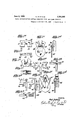
- Fig. 1 is a .plan view of such blank folded to provide a substantially continuous trough defined by connected trough members formed by the'folding of the blank thus far;
- L Fig. 1 is a plan view of the fully formed F ig. 1 is a side elevation of the fully formed key shown in 1 of the drawing;
- Fig. 1 is a longitudinal section of the fully formed key taken along line ee'of Fig. 1 of the drawing;
- Fig. 1 is a transverse sectional view of the fully formed key shown in Fig. 1 of the drawing;
- Fig. 1 is a side elevation of such key'showing the manipulating handle attached thereto;
- Fig. 1 is a top plan view of the fully formed key shown in Fig. 1 of the drawing;
- Fig. 1 is a sectional-view of the fully .formed key shown in Fig. 1 of the drawing taken along line l-l of such figure of the drawing;
- Fig. 1 is a cross sectional view of the fully formed key of Fig. 1 of the drawing taken along line 1 1 of such a figure of the drawing; and.
- 1 is a formed key showing the manipulating handle attached'thereto;
- Fig. 2 is a cross sectional view showing one form oroutline of trough member which may be employed for one type of fastener showing another type of trough member which may be employed for a different type of fastener than that with which the form or outline of kcymember shown in Figs. lto 1 inclusive, of the drawing is intended to be employed; y
- Fig. 3 is a cross section of still another form of trough member adapted for use with still another type of fastener than that with which the keymembers already illustrated are intended to be employed;
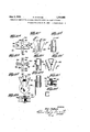
- Fig. 4 is a plan view of a blank for still another illustrative embodiment of the present invention.
- Fig. 4" is a plan view of the blank of Fig. 4 of the drawing folded so as to provide a substantially continuous trough defined by connected trough. members;
- Fig. 4? is 'a front elevation of the key of Figs. 4 and 4" of the drawing in fully assembled form
- front elevation of the fully .14" is a side elevation of the key shown in Fig. 4 of the drawing;
- .Fi 5 is a plan view of still another blank for orming another of the aforesaid illustrative embodiments of the present invention
- Fig. 5 is a plan view of such blank formed so as to provide a substantially continuous trough defined by connected trough members from the blank shown in Fig. 5 of the drawing;
- Fig. 5 is a side elevation of the assembled key formed from the blank illustrated in Figs. 5 and 5 of the drawing;
- Fig. 6 is a plan view of still another form of blank for forming. Still another of the aforesaid illustrative embodiments of the' present invention.
- Fig. 6 is a plan view of the blank of Fig. 6 of the drawing folded soas to provide a substantially continuous trough defined by connected tron h members;
- Fig. 6 is a ront elevation of the key of Figs, 6 and-6 of the drawing in assembled form;
- Fig. .6 is a cross sectional view of the key shown in Fig. 6 of the drawing taken along line 6 6 'of Fig. 6 of the drawing;
- F ig'.,6 is a side elevation of one form of operating handle which may be used with the key illustrated in Figs. 6, 6", 6 and 6 of the drawing; and I i Fig. 6' is a front elevation of the operating handle shown in Fig. 6 of the drawing and further illustrated in assembled form in Fig. 6 of the drawing; y
- Fig. 7? is a plan view of a blank for still another illustrative embodiment of the present invention.
- Fig. 7 b is' a plan View of the blank of Fig.
- Fig. 7 is a front elevation of the key member of Figs. 7 a and 7? of the drawing in fully assembled form;
- Fig. 7 d is a side elevation of the key shown in Fig. 7 of the drawi'ng;
- Fig. 7 is a fragmentary front elevation, partly in section and partly broken away, showing certain details of construction of the key illustrated in Figs. 7, 7*, 7, and 7 of the drawing;
- Fig-7? is a cross sectional view of the same taken along line 7'-7F of Fig. 7 of the drawing; a
- Fig. 8 is a plan view of a blank of still another illustrative embodiment of the presof Fi 8 and 8 of the drawing in fully assem led form;
- Fig. 8 is a side elevation of the key shown in Fig. 8 of the drawing.
- Fig. 9 is a plan view of still another blank for forming the last remaining one of the aforesaid illustrative embodiments of the present invention.
- Fig. 9 is a plan view of the blank of Fig. 9 of the drawing, partly broken away, showing such blank folded so as to provide a substantially continuous trough defined by connected trough members;
- Fig. 9 is a side elevation of the key shown in Figs. 9 and 9 of'the drawing showing such key in fully assembled form;
- Fig. is a plan view of a blank which of Fig. 10 of the drawing;
- Fig.10 is a transverse sectional view of the fully formed key shown in Fig. 10 of the drawing; I
- Fig. 10 is a side elevation of such key 5 showing the manipulating handle attached thereto; 7
- Fig. 10 is a top plan view of the fully formed keyshown in Fig. 10 of the draw- Fig. 10 is a sectional view of the fully formed key shown in Fig. 10 of the drawing 7 taken along line 10-10 of such figure of the drawing;
- Fig. 10 is a cross sectional view of the fully formed key' of Fig. 10 of the drawin taken along line 10 10 of such figure o the drawing; and v Fig. 10 is a front elevation of the fully formed key showing the manipulating handle attached thereto.
- '10 indicates a blank which may be stamped of any suitable metal, such as steel, bra'ss, German silver, or the like, and which preferably comprises a plurality of trough blank membersv 11 and 12 substantiall continuous except that such trough blan portions 11- and 12 may be 'rovided with a cone5 nection portion 13 of re uced width to enTble .
- tive slots 18 and 19' for a folded inwardly to de such trough blank portions 11 and 12, after forcing blank portions 18 and 19.
- the locking and reinforcing blank portions 18 and I 19 are preferably provided with the respecurpose to be described in considerable detail later in this specification.
- the trough blank portions 11 and 12 preferably consist of the bottom wall vortions 11 and 12', and the side wall portions 20,
- ing is now shaped, as shown in Fig. 1". of the drawing, to provide a plurality. of substantially continuous trgfiigh members formed from the trough bla portions Hand 12 of the blank 10.
- the lateral wall portions 20, 20', and 21, 21", of' the trough blank portions 11 and 12, respectively are bent or folded u wardly or downwardly, as the case may e, thus provldmg the substantially continuous. rough member: 11" and 12 connected by the intermediate connecting blank portions 13.
- the flange portions 22 22, and 23, 23' are
- I rovide a handle or mani 'ulating member, ere
- y reference character 28 preferably in the form of a flat tab comprising a main body portion 29 and the opposed ears or lug portions 30 and 31 which may be sprung or otherwise suitably insert- -ed into the ends of the loop portion 26 with which the looking or reinforcing portion 18 is preferably provided.
- the 'key including the handle or manipulat ing meniber,.may be very simply made, con-' handle ormanipulating member may be omitted, so that the complete key, including the manipulating means for the same, consists of a single part.
- the provision of the plurality of trough members, including bottom and side wall members and including also, preferably, though not necessarily, inwardly turned flange portions, which trough members define a plurality of independent but converging fastenerreceivin channels, each fastener-re.- cciving channel. eing separately and independently defined by its respective trough member, is a novel feature of great practical importance since it permits the omission of the usual rivets, spacing means, and means for preventing spreading hitherto employed in the art in the fabrication of keys or operating members for flexible fastening devices, in which structures cooperating channels are. provided by a plurality of overlying wing members requiring the use of rivets, spacing means, and means for preventin the spreading of such wing members.
- the bottom wall member has, been designated trated in by reference character 41, and the converging side wall members b reference characters 42. and 43, the inwar y directed flange P01? tions 44 and 45 being preferably provided t define the fastener-receiving passageway 46.
- the drawing, 'the trough, there generally designated 'b reference character 40 mayv a portions 51 and 52, and the mtervening lockmg or reinforcing member blank portions 53 and 54, respectively slotted at 53' and 54', as shown more clearly in Fi 4 of the drawing.
- This blank is likewise s aped to provide a an plurality of substantially continuous trough members desi ated by reference characters I 51' and 52' in ig. 4" of the drawing.
- the key ortions 55, 55, and 56, 56' which in the y formed condition of the key enter the respective slots 53' and 54', as more clearly shown in Fi 4 and 4'of the drawing.
- e finished key is illustrated in Figs. 4 and 4 of the drawing where 58' designates the formed reinforcing member blank portion 53 roviding means of attachment for the ban e or o ting member or the key permitting slida 1e movement of such handle or operating member from one end to the other of the attaching means 53". Otherwise the construction arrangement of parts and modes of assembly, 0 ration and use of this type of ke or operatm member are the same as .for the ey or operating member illustrated in Fi 1* to 1*, inclusive, of the drawing, as descn in detail above.
- the keytherein illustrated comprises a single unita member made intolly in one piece an roviding in one'and t same integral mem 'r the trough members defining conver g fastener-receiving l0 passagewa s and the andle ormanipulatin or thispurpose, I rovide a bl here-designated by referencec aracter '60 and v including the trough member blank rtions 61 and 62 and the intervening locking and reinforcing member blank portions 68 and erein I have illustrated still an-.
- the.reinforcing member blank portion 63 has been folded to provide the manipulating handle 637 large enough and spaced far enough apart from the converging trough members to provide a sufiicient grip for. the fingers in the, manipulation'ofthe key or operating member along the flexible fastenin device withwhich it is intendedto be use Otherwise the construction, arrangement of parts and modes of assembly, operation and use of the illustrative embodiment of the invention 'ust describedare the same as for the been generally designated by reference character 70.
- the blank comprises the trough member-blank portions 71 and 72 together with the connecting portion73 and the lockmg or reinforcin portions 74, 74', and 75, 75 the 'ortions 4 and 75 being slotted as indica at 74? and 75", respectively, for the reception of the respective locking. portions or ears 74' and 75'.
- the blank is folded so as to provide the substantially aligned "trough members 71 and 72, respectively, after which the trough members so formed are bent in to converging position,'as' shown more clearly in Fig. 6". of the drawing. a
- the locking tongues or ears 74' and are. caused to enterv the respective slots prevlous embodiments illustrated in the. earher figures ofthe drawing as described 74 and 7 5", as shownmore clearly in Fig. I
- the manipulating handle here designated by reference character 76, is preferabl made from a single blank so as to ave the oop or manipulating ortion 77 and the intermediate portions 8 and 79 provided with the transversely bent engaging portions 78? and 7 9' respectively.
- the handle thus formed is inserted within the V-shaped space provided between the converging trough memhers 71' and 72 beneath the connection portion 7 3, as more clearly shown in Fig. 6 of the drawing.
- the handle of ma mpulating member for the key or operating member being described shall be made separately from and shall thereafter be applied to the key proper, as more clearly shown-in Figs. 7 and 7 of the drawing.
- I may use a strap of sheet metal providing a handle 84, such strap being. bent so as to form the loop'portion 85, for attachment of a handle thereto, and the connection portions 86 and 86', which may be soldered or otherwise suitably attached to the converging trough members 81 and 82.
- 90 indicates ablank including the trough member blank portions 91 and 92 and the lntermediate connecting portion 93 provided with the intervening handle attaching portion 94.
- the trough member lank portions 91 and 92 are folded so as to form the substan-' tially aligned trough members 91, and 92, respectively.
- the troughs 91 and 92' so formed are folded into conver ing position, one of the trough member blank portions, such as the trough' member blank 7 portion 91, being preferably provided with the extension 91' for cooperation with the edge portion 92' of the remamlng trough member blank portion 92 to provide locking and reinforcing means for the key, as shown more clearly in Fig. 8 of the draw ng.
- reterence character 95 We provide means for attachment thereto in the finished position of the key or operating member of a handle designated by reterence character 95.
- the blank member 94 is folded o ver, preferably into the position shown in Figs. 8 and 8 of the drawing, in which position one portion 9-1 of the blank member 94 is offset or looped so as to provide means of attachment thereto of the handle 95 by means of the ears or lugs 95 and 95"-'with which such handle is preferably provided.
- ears or lugs 95' and 95" are pre erably sprung into the open ends of the loop portion 94 of'the blank portion 94.
- Theend portion 94" of the blank portion 94 preferably passes through the substantially V-shaped opening between the converging trough members 91' and 92', n winch position it is clamped between such converging trough members so as to provide a secure means of attachment to the key or operating 1 member of the handle 95. It may here be stated that the outer end 94 of the blank portion 94 is preferabl slotted orotherw se formed so as to have loc ing engagement with the rear faces ofthe-converging troughs 91 and 92, as shown more'clearly' m Fig. 8 of the drawing.
- the handle attaching portion 1041s preferably of such length and other dimensions as to provide means for attachment thereto of the handle or manipulating member so that the latter will have a slidable engagement along the key or operating member, as more clearly shown in Fi 9 of the drawing.
- the handle attaching member. 101 is bent down and then back so as to provlde the elongated loop portion 104', the end portlon 104' referably passing through the substantially ll-shaped space defined between the converging trou h 101 and 102, as in the case of the device lllustrated in Flgs. 8, 8 8 and 8 of the drawing, which the device now being described most closely resembles of the various forms of the device hitherto. described.
- a blank 200 having the trough-member blank portions 201 and 202 and, the intermedlate locking and "reinforcin members 203 and 2 04.
- the intermediate loc and reinforcing members 203' and 204 are provided with the slots 203' and 204 respectively for receiving the key portions 205, 205', and 206, 206', re-
- the lugs or locking portions '205,,205','and.206, 206' are wide-enough to permit being folded over through the d are the same 'vely, as more ing member illustrated in Figs. 1* to 1" of the drawing. That is, the locking or reinforcing portions 203 and 204 may terminate adjacent the lower edges of the key or operating member formed of the blank 200, being preferably flush with the lower edges of the trough 201 and 202' illustrated in Figs. 10 of the-drawing, or may even terminate slightly above the lower .edges'of the troughs.
- the blank 200 preferably has the trough member blank portions 201 and 202 thereof folded so as to provide substantially continuous troughs 201' and 202', which are afterwards bent into converging relation with respect to each other, as shown more clearly in Fig.
- a handleattachlng loop portion 207 to which a manipulating handle or member 208 may be attached in the manner already described above.
- the construction, arrangement of parts and modes of assembly, operation and use of this last embodiment of the article of the present invention are substantially thesame as for the illustrative embodiment illustrated in the earlier figures of this drawing, especially Figs. 1" to 1", inclusive, described in the earlier portions-of this specification.
- thekeys of the present invention are simple in constructiom'easy to fabricate and asemble, consist 'of few parts, and are rugged andstrong, thus little liable to get out of order and repair 125 and being also adapted for accurate and convenient operation. over long periods of time. .9 It will befurthertnoted that each of the devices illustrated in the and described 7 above makes use'of a plurality of separate or m no I independent trough members each individually defining a separate fastener-receivingv passageway.
- the device does not make use of an rivets or an cooperating overlying wings efining by t eir cooperation a plurality of channels;
- the device moreover, consists of very few parts, sometimes as few as two parts and in certain inuse will readily occur to those skilled in the art to which the present invention relates.
- fastener-receiving passageway and each comprising a bottom wall member and associated side wall members.
- the method of forming an operating member for flexible fastening devices .and the like which comprises'providing a blank including a plurality of connected trough member blank portions, forming said connected troughmember blank portions into 'a plurality of connected trough members each defining its separate fastener-receiving passageway and each comprising a bottom wall member and associated side .wall members, and
- the method of forming an operating member for flexible fastenin devices and the like which comprises providing a blank including a plurality of connected trough member blank portions, forming said connected trough member blank portions into a'plurality of connected trough members each defining its separate fastener-receiving passageway, and thereafter bringing the con- 'nected trough members so formed into converging relation with respect to each other.
- the method of forming an operating member for flexible fastening devices and the like which comprises providing a blank including a plurality of connected trough member blank portions, forming said connected trough member blank portions into a plurality of substantiall aligned connected trough members each dc ing its separate fastenerreceiving passageway, and thereafter bringing the connected trough members so formed into converging relation with respect to each other.
- the method of forming an operating member for flexible fastening devices and the like which comprises providing a blank including a plurality of connected trough member blank portions and an intermediate reinforcing member blank portion, forming said connected trough member blank portions into a plurality of substantially aligned connected trough members each defining its separate fastener-receiving passageway and each comprising a bottom wall member and associated side wall members, bringing the connected trough members so formed into converging relation with respect to each other, and thereafter bringing said intermediate reinforcing member blank portion into position to reinforce the trough member.
- the method of forming an operating member for flexible fastening devices and the like which comprises providing a blank including a plurality of connected trough member blank portions and an intermediate reinforcing member blank portion, forming said connected trough member blank portions into a plurality of substantially-aligned connected trough members each defining its separate fastener-receiving passageway, bringing the connected trough members so formed into converging relation with respect to each other, and thereafter. bringing said intermediate reinforcing member blank portion into position to reinforce the trough member so formed.
- the method of forming an operating member for fiexible fastening devices and the like which comprises providing a blank in cluding a plurality of trough member blank portions and an intermediate reinforcing member blank portion, forming said trough member blank portions into a plurality of substantially aligned trough members each defining its separate fastener-receiving passageway and each comprising a bottom. wall member and associated side wall members, and thereafter bringing said intermediate reinforcing member blank portion into posiv tion' to reinforce the trough member so formed.
- the methodof forming an operating member for flexible fastening devices and the like which comprises providing a blank including a plurality of trough member blank portions and an intermediate reinforcing member blank portion, forming said trou h member blank portions into a plurality ofsu stantially aligned trough members each defining its separate fastener-receiving passageway, and thereafter bringing said intermediate reinforcing member blank portion into position to reinforce the trough member soformed.
- A, blank for an operating member for flexible fastening devices and the like comprising a plurality of connected trough member blank portions each adapted to define an independent and separate passageway and an intermediate blank portion providing reinforcing means.
- a blank for an operating member for flexible fastening devices and the like com prising a plurality of connected trough member blank portions each adapted to define an independent and separate passageway and an intermediate blank-portion providing reinforcing means and providing also means for attachment thereto of a manipulating member.
- a blank for an operating member for flexible fastening devices and the like comprising a plurality of connected trough member blank portions each providing a bottom 'wall blank portion and associated side wall blankportions, and an intermediate blank portion providing reinforcing means.
- a blank for an operating member for flexible fastening devices and the like comrising a plurality of connected trough memer blank portions each providing a bottom wall blank portion and associated side wall blank portions, and an intermediate blank portion providing reinforcin means and providing also means for attac ment thereto of a manipulating'member.
- A-blank for an operating member for flexible fastening devices and the like comprising a plurality of connectedftijough mom-I ber blank portions each providing a'bottomwall blank portion and associated side wall blank portions together with one or more locking portions, and an intermediate blank portion providing reinforcing means.
- a blank for an operating member for flexible fastening devices and the like comprising a plurality of connected trough member blank portions each providing a bottom wall-blank portion and associated side wall blank portions together with one or more locking portions, and an intermediate blank portion providing reinforcin means, said intermediate blank portion bemg perforated g5 forcooperation with said locking portion or portions.
- a blank for an operating member for flexible fastening devices and the like comprising aplurality of connected trough memao ber blank portions each providin a bottom wall blank portion and associate side wall blank portions together with one or more locking portions, and an intermediate blank portion providing reinforcing means and providing also means for attachment thereto of a mampulatin member, said intermediate blank portion belng perforated for cooperation with said locking portion or portions.
- a blank for an operating member 40 for flexible fastening devices and the like a plurality of connected trough member blank portions, each adapted to define an independent and separate passageway.
Landscapes
- Engineering & Computer Science (AREA)
- Mechanical Engineering (AREA)
- Making Paper Articles (AREA)
Description
fiame 3, 193%. N. STATHAM METHOD OF FABRICATING FASTENER OPERATING MEANS AND BLANK THEREFOR Original Filed March 25, 1926 4 Sheets-Sheet l mmvroa A/oe/J/a/Zmn BY ATTORNEY N. STATHAM June 3,1930.
IB'I'HOD OF FABRICATING FASTENER OPERATING [BANS AND BLANK THEREFOR Original Filed larch 25, 1926 4 Sheets-Shoot 2 IN VEN TOR.
Jl me 3, 193 0. sTATHAM LHT LSQS METHOD OF FABRICATING FASTENEROPERATING MEANS AND BLAHK TKEHEFOR 1 Original Filed Marsh 25. 1926 4 Sheets-5mm 5 l 1 um INV EN TOR.
- ATTORNEY June 3, 1930. N. STATHAM IETHOD OF FABRICATING-FASTENE'R OPERATING MEANS AND BLANK THEREFOR 4 Sheetg-Sheet 4 Original Filed March 25, 1926 IV ,Lsblz mmvroa I ATTORNEY Patented June 3, 1930 PATENT OFFICE NOEL STATHAM, F IRVINGTON-UPON-HUDSON, NEW YORK METHOD OF FABRICATING FASTENER-OPERATING MEANS AND BLANK THEREFOR Original application flied March 25, 1926, Serial No. 97,216. Divided and this application filed June 9,
' 1926. Serial No. 114,786.
. My present invention relates to'methods of fabricatin keys or operating members for slidable Fasteners and'the like, as well as to blanks which may be used for fabricate ing such keys or operating members, and
aims to devise methods for fabricating articles of the general character specified'which are simple to practice, which render possible the economical fabrication of such keys or operating members in a novel, direct and ex peditious manner, and which may be employed for the fabrication, for example, of two or even one piece keys or operating members of the general character specified above, the keys or operating -members resulting from the practice of the methods of the pres ent invention being characterized by their few parts, in. the preferred cases, only two or even only one part, rather than three or more parts, the simplicity of such parts, the ease, economy and convenience with which such parts may be assembled in the fabrication of the-finished key or operating member of the present invention, the ease and convenience in operation of such keys or operatmg members, and the avoidance 1n the structure of such keys or operating members of rivets or like separate means, passing through the devices orotherwise, for fastening or assembling such devices, and the avoidance in the structure of the devices of the present invention of the use of a plurality of wings, in overlying position or the' like, to define a plurality of fastener-receiving channels, the keys or operating members of the present invention being preferably characterized by their embodiment of a pair of troughs or trough-like members each of which, independently of the other trough- 43 like member, defines its own single and independent internal passageway instead of only partially or incompletely defining a plurality of passageways which are completed only by another portion of the device. Other 4 advantages and objects of the methods and products of the present invent-ionwill in part be pointed out in detail hereinafter and will in part be obvious to thosev skilled in the art to which the present invention relates. The keys or operating members themselves form no part of the present invention being fully claimed in a copending application of mine filed March 25, 1926, Ser. No. 97 ,216, entitled Fastener-operating means, of which this application is a division.
In the accompanying specification'I shall describe several illustrative embodiments of the methods of the present invention. In the accompanying specification I shall also describe, and in the annexed drawing illustrate, several illustrative embodiments of the blanks of the present invention. It is, however, to be clearly understood that my invention is not limited to the specific forms of the aforesaid illustrative embodiments of the methods and articles of the present invention shown and described herein by way of illustration only, except as defined in the appended claims.
Referring now to the aforesaid illustrative embodiments of the present invention, and
more particularly to the aforesaid illustra tive embodiments of the methods of the present invention, such methods, in their preferred forms, may be defined as the provision, in the first instance, of a blank, preferably unitary, having a plurality of trough member blank ortions and an intermediate connecting portlon joining such trough blank portions. he intermediate joining portion is preferably of reduced width as compared with the average width of the trough member blank portions, for a purpose to be described later in this specification. The blank is preferably also provided with a looking or reinforcing blank portion which may be an extension either of the intermediate or join 'ing blank portion, or of one or both of the trough member blank portions, or of any con'ibination of these portions. There is also provided an attachment blank portion for formation into means for attachment to the device of a handle or the like which such a handle or the like is desired to form a part of the finished device. where no separate handle is vdesired to be em bodied in the devices of the present in ention, this attachment blank portion may take the form of a handle blank portion which is In those instances members to converge.
adapted to be sha ed into a handle in the device in its final orm. v
The trough member blankportions are each preferably adapted to be shaped into separate or independent trough memberseach defined by a bottom wall member and by side wall members, which latter may also have inwardly directed flange portions to define, in the desired manner, the internal passageway contained within each trough member for receiving the fastenersand the fastcnei suppm'ti11g tape forming a part of the flexible fastening devices with which the keys or operating members of the present invention are intended to be employed. The connecting portion joining the two trough member blank' portions is preferably of reduced width so that it may be bent, preferably after the trough members have been shaped into trough-like form, as already indicated above, in order to mu e such trough The locking or reinforcing blanl5;: portion is preferably so shaped and disposed as to adequately serve its function of looking or reinforcing the trough members. Finally, the attachment blank portion is of such form and is so disposed as to adequately serve its intended function of serving as an efficient attachment means for a handle or like device to permit the manual operation of the finished key or operating member along the flexible fastening device with which such key .or operating member is intended to be used, in the case where a separate handle for such purpose is desired to be embodied in the finished devices of the present invention. On the other hand,
where no such separate handle is desired, such attachment blank portion provides a blank portion for shaping an integral handle or manipulating member.
In fabricating the keys or operating members according to the methods of the present invention, I take a blank, preferably a unitary blank, such as defined above, and sha e it initially so as to provide a; substantia -y continuous trough from end to end, except that the side walls or portions of the trough may be, and generally are, omitted at the connecting portion, preferably of reduced width, joining the trough member blank portions. The joined trough members "thus formed will 'each have a bottom wall and a plurality ofjoining sidewalls, together., pref-' erably, with inwardly turned flanges for defining a passageway which, in the condition of the formed blank thus far described, is a substantially continuous passa ewa from other. This passageway is preferably subformed, the trough members, making up what may betermed the continuous trough,
am t in number and are adapted to brought into converging position by-being any further looking or rei of the connecting sidewalls, together, preferably, witha pair so of inwardly directed flanges for constricting such passageway.
While, in certain cases, this structure is sufficientvof itself, andinay-be so employed, for the uses of the present invention without rcipg means, I prefer to lock or otherwise joirf the trough incmbers'so formed adjacent their point of proximity or contact. I may do this either as soldering or welding, or I may use a locking or reinforcing blank portion, as already with any suitable metal joining means, such described above, which may be bent over 1n a suitable manner to lock the two trough members together.
I new shape the attachment blank portion,
where such portion is to be used for serving as attachment means for a separate handle or manipulating member for the device, so as to adapt the samefor attachment to such handle or manipulating device. On the other hand, where no separate handle or manipulab ing device is to be used, but such handle or' manipulating device is to constitute an integral part of the devices of the prcsent'invention, I so shape the attachment blank portion as to provide such an integral handle or manipulating device.
This completes the description of the' methods of the present invention, as exemplified in the aforesaid illustrative embodiments of the same. Such methods are simple to practice, easy and convenient to 'carry out, and
result in a strong structure which preferably comprises only two parts or even only a single part. The methods of the present invention avoid the use of a rivet or equivalent independent fastening means which has to pass through the device to assemble the same or keep the same in proper spaced relation. Due
also to the formation of the independent trough members, as defined above, each comprising a bottom wall and joining side walls,
no spacing means are-required, as would be 1 the case where a plurality of wings in over- .'lying or like position are employed defining between them, by their cooperation, a plurality of channels.-. For the same reason, no
means are required for preventing spreading, as is required in the case'of the doublewing construction hitherto, employed in the art.
Referringnow to the drawings, wherein I have illustrated the'aforesaid illustrative em-' illustrative embodiments of the present in-' vention;
Fig. 1" is a .plan view of such blank folded to provide a substantially continuous trough defined by connected trough members formed by the'folding of the blank thus far; L Fig. 1 is a plan view of the fully formed F ig. 1 is a side elevation of the fully formed key shown in 1 of the drawing;
Fig. 1 is a longitudinal section of the fully formed key taken along line ee'of Fig. 1 of the drawing;
Fig. 1 is a transverse sectional view of the fully formed key shown in Fig. 1 of the drawing;
Fig. 1 is a side elevation of such key'showing the manipulating handle attached thereto; v
Fig. 1 is a top plan view of the fully formed key shown in Fig. 1 of the drawing;
Fig. 1 is a sectional-view of the fully .formed key shown in Fig. 1 of the drawing taken along line l-l of such figure of the drawing;
Fig. 1 is a cross sectional view of the fully formed key of Fig. 1 of the drawing taken along line 1 1 of such a figure of the drawing; and.
1 is a formed key showing the manipulating handle attached'thereto;
Fig. 2 is a cross sectional view showing one form oroutline of trough member which may be employed for one type of fastener showing another type of trough member which may be employed for a different type of fastener than that with which the form or outline of kcymember shown in Figs. lto 1 inclusive, of the drawing is intended to be employed; y
Fig. 3 is a cross section of still another form of trough member adapted for use with still another type of fastener than that with which the keymembers already illustrated are intended to be employed;
Fig. 4 is a plan view of a blank for still another illustrative embodiment of the present invention;
Fig. 4" is a plan view of the blank of Fig. 4 of the drawing folded so as to provide a substantially continuous trough defined by connected trough. members;
Fig. 4? is 'a front elevation of the key of Figs. 4 and 4" of the drawing in fully assembled form; and
front elevation of the fully .14" is a side elevation of the key shown in Fig. 4 of the drawing;
.Fi 5 is a plan view of still another blank for orming another of the aforesaid illustrative embodiments of the present invention Fig. 5 is a plan view of such blank formed so as to provide a substantially continuous trough defined by connected trough members from the blank shown in Fig. 5 of the drawing; and
Fig. 5 is a side elevation of the assembled key formed from the blank illustrated in Figs. 5 and 5 of the drawing;
Fig. 6 is a plan view of still another form of blank for forming. still another of the aforesaid illustrative embodiments of the' present invention;
Fig. 6 is a plan view of the blank of Fig. 6 of the drawing folded soas to provide a substantially continuous trough defined by connected tron h members;
Fig. 6 is a ront elevation of the key of Figs, 6 and-6 of the drawing in assembled form;
Fig. .6 is a cross sectional view of the key shown in Fig. 6 of the drawing taken along line 6 6 'of Fig. 6 of the drawing;
F ig'.,6 is a side elevation of one form of operating handle which may be used with the key illustrated in Figs. 6, 6", 6 and 6 of the drawing; and I i Fig. 6' is a front elevation of the operating handle shown in Fig. 6 of the drawing and further illustrated in assembled form in Fig. 6 of the drawing; y
Fig. 7? is a plan view of a blank for still another illustrative embodiment of the present invention;
Fig. 7 b is' a plan View of the blank of Fig.
7 of the drawing folded so asvto provide a:
substantially continuous trough defined by 7 connected trough members;
Fig. 7 is a front elevation of the key member of Figs. 7 a and 7? of the drawing in fully assembled form;
Fig. 7 d is a side elevation of the key shown in Fig. 7 of the drawi'ng;
Fig. 7 is a fragmentary front elevation, partly in section and partly broken away, showing certain details of construction of the key illustrated in Figs. 7, 7*, 7, and 7 of the drawing; and
Fig-7? is a cross sectional view of the same taken along line 7'-7F of Fig. 7 of the drawing; a
Fig. 8 is a plan view of a blank of still another illustrative embodiment of the presof Fi 8 and 8 of the drawing in fully assem led form; and
Fig. 8 is a side elevation of the key shown in Fig. 8 of the drawing;
Fig. 9 is a plan view of still another blank for forming the last remaining one of the aforesaid illustrative embodiments of the present invention;
Fig. 9 is a plan view of the blank of Fig. 9 of the drawing, partly broken away, showing such blank folded so as to provide a substantially continuous trough defined by connected trough members; and
Fig. 9 is a side elevation of the key shown in Figs. 9 and 9 of'the drawing showing such key in fully assembled form;
' r Fig. is a plan view of a blank which of Fig. 10 of the drawing;
, Fig.10 is a transverse sectional view of the fully formed key shown in Fig. 10 of the drawing; I
Fig. 10 is a side elevation of such key 5 showing the manipulating handle attached thereto; 7
Fig. 10 is a top plan view of the fully formed keyshown in Fig. 10 of the draw- Fig. 10 is a sectional view of the fully formed key shown in Fig. 10 of the drawing 7 taken along line 10-10 of such figure of the drawing;
' Fig. 10 is a cross sectional view of the fully formed key' of Fig. 10 of the drawin taken along line 10 10 of such figure o the drawing; and v Fig. 10 isa front elevation of the fully formed key showing the manipulating handle attached thereto.
Referring now to the aforesaid illustrative embodiments of the articles. of the present invention, and more particularly to the drawings illustrating the same, and with-special reference to the embodiment of the in- .vention shown 'in' Figs. 1", 1, 1, 1", 1, 1, 1 1 1 ,1 and 1 of the'drawing, '10 indicates a blank which may be stamped of any suitable metal, such as steel, bra'ss, German silver, or the like, and which preferably comprises a plurality of trough blank membersv 11 and 12 substantiall continuous except that such trough blan portions 11- and 12 may be 'rovided with a cone5 nection portion 13 of re uced width to enTble .tive slots 18 and 19' for a folded inwardly to de such trough blank portions 11 and 12, after forcing blank portions 18 and 19. The locking and reinforcing blank portions 18 and I 19 are preferably provided with the respecurpose to be described in considerable detail later in this specification.
The trough blank portions 11 and 12 preferably consist of the bottom wall vortions 11 and 12', and the side wall portions 20,
20', and 21,21, respectively. Thereare also provided as a part of the side wall blank portions 20, 20, and 21, 21', thefian'ge por tions 22, 22', and 23, 23, for a urpose to be described in greater detail su sequenth in this specification. Also forming a part 0 the lateral wall, portions .20, 20", and 21, 21', are the key portions 24, 24', and 25, 25'
spectively, formed in the locking and reinforcing members 18 and 19.
j v for- .cooperation with the slots18' and19, re-
. The blank 10 shown in Fig. 1" of the draw,-
ing is now shaped, as shown in Fig. 1". of the drawing, to provide a plurality. of substantially continuous trgfiigh members formed from the trough bla portions Hand 12 of the blank 10. For this purpose, the lateral wall portions 20, 20', and 21, 21", of' the trough blank portions 11 and 12, respectively, are bent or folded u wardly or downwardly, as the case may e, thus provldmg the substantially continuous. rough member: 11" and 12 connected by the intermediate connecting blank portions 13. At the same time, or in another. forming operation, the flange portions 22 22, and 23, 23', are
line therespective pas-' sageways' 22"" and 23". Likewise, either 91- multaneously with, or in a formiizg o eration separate from, either or both of e orr'ning operations already referred to, the ke v portions 24, 24, and 25, 25', are folde outwardlyinto the positions shown in Fig. 1? of the drawing. 7
In theanextro Ieration, the" trough members 11" andc12Q- efinin'g the passageways 22" and 23" respectively,'arebent adjacent the points 1 nd 13", respectively, of the intermediate connecting portion 13 so as to be brought iiitothe contacting or convergmg o- W clearly shown in, Figs. 1 an 1 wing. After this 0 eration has m ted, or simultaneous y with; such operatic or with any one ormore of the ipreens, the-lockin and rein orcgand 19-are f0 deddownover the loc ing or reinforcing member 18, and
likewise at an intermediate point of the key as a whole, preferably above the center of such locking and reinforcing member and above the center of such key as a whole, for the purpose of providing a means of attachment to the key of a handle or other suitable manipulating member for the key. In completing the key member thus far described, the lower extremities of the locking and reinforcing members 18 and 19, here indicated by reference characters 18" and 19",
may be'inwardly turned, as more clearly shown in Figs. 1, 1 and 1 of the drawing, to further reinforce the key which has been generally designated by reference character To complete the key, it is desirable to I rovide a handle or mani 'ulating member, ere
generally designated y reference character 28, and preferably in the form of a flat tab comprising a main body portion 29 and the opposed ears or lug portions 30 and 31 which may be sprung or otherwise suitably insert- -ed into the ends of the loop portion 26 with which the looking or reinforcing portion 18 is preferably provided.
This completes the description of the construction and mode of assembly of the first of the aforesaid illustrative embodiments of the present invention, as illustrated in Figs. 1 .to 1 inclusive, of the drawing. The manner of using the key made from the blank comprisingithe aforesaid illustrative embodiment of the present invention will be clear to those skilled in the art to which the present invention relates and need not be further described herein except to state that such key is threaded over the two cooperating flexible fastener-supporting elements carrying opposed cooperating pairs of fasteners of any suitable type, the key being adapted in one direction of its movement along the flexible fastening device with which it is intended to be used to lock cooperating pairs of fasteners and in the opposite direction of its movement along such flexible fastening device to open such cooperating pairs of fasteners.
The advantages of theforegoing illustra tive embodiment of the present invention are numerous and of great practicalimportancei In the first place, by means of such a blank, the 'key, including the handle or manipulat ing meniber,.may be very simply made, con-' handle ormanipulating member may be omitted, so that the complete key, including the manipulating means for the same, consists of a single part.
Furthermore, the provision of the plurality of trough members, including bottom and side wall members and including also, preferably, though not necessarily, inwardly turned flange portions, which trough members define a plurality of independent but converging fastenerreceivin channels, each fastener-re.- cciving channel. eing separately and independently defined by its respective trough member, is a novel feature of great practical importance since it permits the omission of the usual rivets, spacing means, and means for preventing spreading hitherto employed in the art in the fabrication of keys or operating members for flexible fastening devices, in which structures cooperating channels are. provided by a plurality of overlying wing members requiring the use of rivets, spacing means, and means for preventin the spreading of such wing members. By 't e avoidance of the use of wings, such rivets, spacing means and means for preventin spreading of the wings are entirely avoide The key made from the aforesaid illustrative embodiment of the present inventionis further characterized by its stren h, its little likelihood to get out of order an require .re- 7 pair, and the ease, convenience and accuracy with which it carries out the desired opening and closing operations when used with the flexible fastening devices with which it is intended to be employed. Other advantages and superiorities of such embodiment of the invention Will readil occur to those skilled in the art to which t e present invention refile of the trough member to accommodate fasteners and fastening devices of different forms and configurations may be made. For example, while the trou h members ma be given the contour or pro e illustrated in ig.
1 of the drawing, where such contour or pro-.
file is substantially square or rectangular,
they may as readily be iven the contour or profile shown in Fig. 2 o the drawing, where. such contour or profile is substantially trapezoidal. In such form of the trough member, v
here designated by reference character 40,
the bottom wall member has, been designated trated in by reference character 41, and the converging side wall members b reference characters 42. and 43, the inwar y directed flange P01? tions 44 and 45 being preferably provided t define the fastener-receiving passageway 46.
On the other hand, as shown in Fig. 3 of the drawing, more complicated forms or contours of the troughs may be just as readily made, as in the case of the simpler forms of the m troughs illustrated in Figs. 1 and 2 of the drawing. In the form illustrated in Fig.3 of
the drawing, 'the trough, there generally designated 'b reference character 40, mayv a portions 51 and 52, and the mtervening lockmg or reinforcing member blank portions 53 and 54, respectively slotted at 53' and 54', as shown more clearly in Fi 4 of the drawing. This blank is likewise s aped to provide a an plurality of substantially continuous trough members desi ated by reference characters I 51' and 52' in ig. 4" of the drawing. At the same time there are provided the key ortions 55, 55, and 56, 56', which in the y formed condition of the key enter the respective slots 53' and 54', as more clearly shown in Fi 4 and 4'of the drawing.
e finished key is illustrated in Figs. 4 and 4 of the drawing where 58' designates the formed reinforcing member blank portion 53 roviding means of attachment for the ban e or o ting member or the key permitting slida 1e movement of such handle or operating member from one end to the other of the attaching means 53". Otherwise the construction arrangement of parts and modes of assembly, 0 ration and use of this type of ke or operatm member are the same as .for the ey or operating member illustrated in Fi 1* to 1*, inclusive, of the drawing, as descn in detail above.
Referringlnow to Figs. 5, 5",'and 5 of the drawillilg, other w ustr'ative embodiment of the present invention, the keytherein illustrated comprises a single unita member made intolly in one piece an roviding in one'and t same integral mem 'r the trough members defining conver g fastener-receiving l0 passagewa s and the andle ormanipulatin or thispurpose, I rovide a bl here-designated by referencec aracter '60 and v including the trough member blank rtions 61 and 62 and the intervening locking and reinforcing member blank portions 68 and erein I have illustrated still an-.
64, respectively provided with the slots 63' and 64. Here alsothe blank is folded, as shown more clearly in Fig. 5 of the drawing, to provide a plurality of substantially aligned trough members 61' and 62 which may then be folded down into converging position in the arrangement more clearly shown in Fig. 5 of the drawing. At the same time there are formed onthe trough member blankportions 61 and 62 the key portions 65,- 65, and 66, 66", whichenter the respective. slots 63 and 64 I In the full formed position of the parts, as more clear y shown in Fig. 5 of the drawing,,the.reinforcing member blank portion 63 has been folded to provide the manipulating handle 637 large enough and spaced far enough apart from the converging trough members to provide a sufiicient grip for. the fingers in the, manipulation'ofthe key or operating member along the flexible fastenin device withwhich it is intendedto be use Otherwise the construction, arrangement of parts and modes of assembly, operation and use of the illustrative embodiment of the invention 'ust describedare the same as for the been generally designated by reference character 70. The blank comprises the trough member- blank portions 71 and 72 together with the connecting portion73 and the lockmg or reinforcin portions 74, 74', and 75, 75 the 'ortions 4 and 75 being slotted as indica at 74? and 75", respectively, for the reception of the respective locking. portions or ears 74' and 75'.
Here also the blank is folded so as to provide the substantially aligned " trough members 71 and 72, respectively, after which the trough members so formed are bent in to converging position,'as' shown more clearly in Fig. 6". of the drawing. a In this position of the parts, the locking tongues or ears 74' and are. caused to enterv the respective slots prevlous embodiments illustrated in the. earher figures ofthe drawing as described 74 and 7 5", as shownmore clearly in Fig. I
6"of the drawing, thus completing the main portion of the key or operating member.
:The manipulating handle, here designated by reference character 76, is preferabl made from a single blank so as to ave the oop or manipulating ortion 77 and the intermediate portions 8 and 79 provided with the transversely bent engaging portions 78? and 7 9' respectively. The handle thus formed is inserted within the V-shaped space provided between the converging trough memhers 71' and 72 beneath the connection portion 7 3, as more clearly shown in Fig. 6 of the drawing. The engagement of the inner or bottom walls of the trough members 71 and 72" with the intermediate portions 7 8' and 79 and with the engaging portions 78' and 7 9' of the manipulating handle 7 6 looks such handle securely in place after the looking ears or lugs 74 and 7 5' have been caused to-enter the respective slots 74" and 75 in the completion of the device. Otherwise, the construction, arrangement of parts and modes of assembly, operation and use of the illustrative embodiment of the devices of the presand the connecting portion 83. Here alsothe trough member blank portions 81 and 82 a are bent up, as shown more clearly in Fig. 7"
oft-he drawing,- to provide a plurality of substantially aligned troughs-81 and 82 which may thereafter be bent into converging position, as shown more clearly in Fi 7 of the drawing. -In. order to lock and reinforce the converging troughmembers 81 and 82'. I prefer to provide one of the trough member blank portions, such' as the trough member blank portion 81, with the lockin and reinforcing portion 81" which may e bent or folded in under the edge portion 82" of the remaining trough member-blank portion 82 in the position more clearly shown in Fig. 7 of the drawing; g
Here also I prefer that the handle of ma mpulating member for the key or operating member being described shall be made separately from and shall thereafter be applied to the key proper, as more clearly shown-in Figs. 7 and 7 of the drawing. Forthis purpose I may use a strap of sheet metal providing a handle 84, such strap being. bent so as to form the loop'portion 85, for attachment of a handle thereto, and the connection portions 86 and 86', which may be soldered or otherwise suitably attached to the converging trough members 81 and 82. 87 indicates the tab or manipulating portion of the handle shown as provided with a plurality of ears 88 and89 which enter, into the open ends of theloop portion ofthe attaching means 84,"as'by;-being sprung into such open ends of the 100p. Y
This completes the description of they-construction and mode of assembly of the key or operating member shown in Figs. 7 7 7, 7 and 7 of the drawing. Otherwise the construction, arrangement of parts and modes O assembly, operation and use of' this form ot' the device are substantially the same as for the forms of the device illustrated in the earlierfigures of the drawing and described in the earlier portions of this specification.
Turning-now to Figs. 8, 8, 8, and 8 of the drawing, wherein I have illustrated still another of the aforesaid'illustrative embodiments of the present invention, 90 indicates ablank including the trough member blank portions 91 and 92 and the lntermediate connecting portion 93 provided with the intervening handle attaching portion 94. Here also the trough member lank portions 91 and 92 are folded so as to form the substan-' tially aligned trough members 91, and 92, respectively. Thereafter, the troughs 91 and 92' so formed are folded into conver ing position, one of the trough member blank portions, such as the trough' member blank 7 portion 91, being preferably provided with the extension 91' for cooperation with the edge portion 92' of the remamlng trough member blank portion 92 to provide locking and reinforcing means for the key, as shown more clearly in Fig. 8 of the draw ng.
We provide means for attachment thereto in the finished position of the key or operating member of a handle designated by reterence character 95. For this purpose the blank member 94 is folded o ver, preferably into the position shown in Figs. 8 and 8 of the drawing, in which position one portion 9-1 of the blank member 94 is offset or looped so as to provide means of attachment thereto of the handle 95 by means of the ears or lugs 95 and 95"-'with which such handle is preferably provided. For this pur ose such ears or lugs 95' and 95" are pre erably sprung into the open ends of the loop portion 94 of'the blank portion 94.
clearly shown in Figs. -'*'and 10 of the draw thus i g the necessity of turning for the forms of the invention illustrated in the earlier figures of the drawing and 'described in the earlier portions of this specification. Turning nowto the last remainlng lllustrative embodiment of the present invention, and referring more particularly to Figs.
. 9, 9 and 9 of the drawing illustrating the same, I have therein shown a blank 100 in- 30 eluding the trough member blank portions 101 and 102 and the connecting portion 103 provided with the intervening handle attaching portion 104. Here also the trough member blank portions 101 and 102 are folded so as to provide substantially contmuous I or aligned troughs 101 and 102,respect1vely.
"The handle attaching portion 1041s preferably of such length and other dimensions as to provide means for attachment thereto of the handle or manipulating member so that the latter will have a slidable engagement along the key or operating member, as more clearly shown in Fi 9 of the drawing. For th s purpose, the handle attaching member. 101 is bent down and then back so as to provlde the elongated loop portion 104', the end portlon 104' referably passing through the substantially ll-shaped space defined between the converging trou h 101 and 102, as in the case of the device lllustrated in Flgs. 8, 8 8 and 8 of the drawing, which the device now being described most closely resembles of the various forms of the device hitherto. described. Otherwise the construction, arrangement of 6-parts and modes of assembl operation and use of the device just descri as for the form of the device illustrated in Figs. 8, 8", 8, and 8 of the draw v t being clear that the handle or operating evice here designated by reference ,0 aracter 105 is Slldably arranged for slidable manipulation from one end to the other of the hay or operating member'to which it is attache In the form of the device illustrated in Fi 102 'to 10 inclusive, which most closely resembles the he illustrated in Fi s. 1 to 1 inclusive, of t e drawing, and escribed 1n detail in the earlier portions of this specification. That is, there is provided a blank 200 having the trough-member blank portions 201 and 202 and, the intermedlate locking and "reinforcin members 203 and 2 04. The intermediate loc and reinforcing members 203' and 204 are provided with the slots 203' and 204 respectively for receiving the key portions 205, 205', and 206, 206', re-
spectively, in the-formed position of the parts,
as more clearly shown m Figs. 10 and 10 of the drawing.
- In thiscas'e the lugs or locking portions '205,,205','and.206, 206', are wide-enough to permit being folded over through the d are the same 'vely, as more ing member illustrated in Figs. 1* to 1" of the drawing. That is, the locking or reinforcing portions 203 and 204 may terminate adjacent the lower edges of the key or operating member formed of the blank 200, being preferably flush with the lower edges of the trough 201 and 202' illustrated in Figs. 10 of the-drawing, or may even terminate slightly above the lower .edges'of the troughs.
Inthis form of the device, also the blank 200 preferably has the trough member blank portions 201 and 202 thereof folded so as to provide substantially continuous troughs 201' and 202', which are afterwards bent into converging relation with respect to each other, as shown more clearly in Fig. '10 of the drawing, after which the locl'ring and reinforcing members 203 and 204 may be folded down over the converging troughs 201' and 202 so as'to cause the lockmg lugs 205, 205, and 206, 206', to ass through the respective apertures 203' an 204, after which the blank portions comprising such locking lugs 205, 205, and 206, 206, may be folded down over the respective locking or reinforcing mem-. V bers 203 and 204 to thus complete the device, the width of the lockin lugs 205, 205','a nd 206, 206, permitting t is operation, as already described above.
As in the case of the key or operating member illustrated in Figs. 10 to 10", inclusive, of the drawing, there is provided in one of the locking or reinforcing members, as in the locking or reinforcing member 203, a handleattachlng loop portion 207 to which a manipulating handle or member 208 may be attached in the manner already described above. Otherwise, the construction, arrangement of parts and modes of assembly, operation and use of this last embodiment of the article of the present invention are substantially thesame as for the illustrative embodiment illustrated in the earlier figures of this drawing, especially Figs. 1" to 1", inclusive, described in the earlier portions-of this specification.
This com letes the description of the aforesaid ustrative 1 embodiments of the present invention. It is, however, to be clearly understood that the inventionis not limited to the specific forms thereof illustrated in the drawing.
It will be seen that thekeys of the present invention are simple in constructiom'easy to fabricate and asemble, consist 'of few parts, and are rugged andstrong, thus little liable to get out of order and repair 125 and being also adapted for accurate and convenient operation. over long periods of time. .9 It will befurthertnoted that each of the devices illustrated in the and described 7 above makes use'of a plurality of separate or m no I independent trough members each individually defining a separate fastener-receivingv passageway. Furthermore, the device does not make use of an rivets or an cooperating overlying wings efining by t eir cooperation a plurality of channels; The device, moreover, consists of very few parts, sometimes as few as two parts and in certain inuse will readily occur to those skilled in the art to which the present invention relates.
What I claim as my invention is: v 1. The method of forming an operating member for flexible fastening devices and the like which com rises providing a blank including a plurality of trough member blank portions, and thereafter forming said trough member blank portions into a plurality of trough members each defining its separate fastener-receiving passageway.
2. The method of forming an operating member for flexible fastenim devices and the like which com rises providing a blank ineluding a plura ity of trough member .blank portions, and thereafter forming said trou h member blank portions into a plurality of su stantially aligned trough members each defining its separate fastener-receiving passageway. v
3. The method of forming an operating member for flexible fastening devices and the like, which comprises providing a blank in eluding a plurality of trough member blank portions, and thereafter forming said trough member blank portions into a plurality of trough members e'ach'defining its separate.
fastener-receiving passageway and each comprising a bottom wall member and associated side wall members.
4. The method of forming an operating member for flexible fastening devices and the like which com rises providing a blank ineluding a plura ity of trough member blank portions, and thereafter forming said trough member blank ortions into a plurality of substantially aligned trough members-each defining its separate fastener-receiving passageway andzeach comprising a bottom wall member and associated side wall members.
5. The method of forming an operating member for flexible fastening devices .and the like which comprises'providing a blank including a plurality of connected trough member blank portions, forming said connected troughmember blank portions into 'a plurality of connected trough members each defining its separate fastener-receiving passageway and each comprising a bottom wall member and associated side .wall members, and
thereafter bringing the connected trough members so formed into converging relation with respect to each other.
6. The method of forming an operating member for flexible fastenin devices and the like which comprises providing a blank including a plurality of connected trough member blank portions, forming said connected trough member blank portions into a'plurality of connected trough members each defining its separate fastener-receiving passageway, and thereafter bringing the con- 'nected trough members so formed into converging relation with respect to each other.
7 The method of forming an operating member for flexible fastening devices and the like, which comprises providing a blank ineluding a plurality of connected trough member blank portions, forming said connected trough member blank portions into a plurality of substatially aligned connected trough members each defining its separate fastenerreceiving passageway and each comprising a bottom wall member and associated side wall members, and thereafter bringin the con- -neeted trough members so forme into converging relationwith respect to each other.
8. The method of forming an operating member for flexible fastening devices and the like, which comprises providing a blank including a plurality of connected trough member blank portions, forming said connected trough member blank portions into a plurality of substantiall aligned connected trough members each dc ing its separate fastenerreceiving passageway, and thereafter bringing the connected trough members so formed into converging relation with respect to each other.
9. The method of forming an operating member for flexible fastening devices and the like, which comprises providing a blank including a plurality of connected trough member blank portions and an intermediate reinforcing member blank portion, forming said connected trough member blank portions into a plurality of substantially aligned connected trough members each defining its separate fastener-receiving passageway and each comprising a bottom wall member and associated side wall members, bringing the connected trough members so formed into converging relation with respect to each other, and thereafter bringing said intermediate reinforcing member blank portion into position to reinforce the trough member. so
' member and associated side wall members,
bringing the connected trough members so formed into converging relation withrespect to each other, and thereafter bringing said intermediate reinforcing member blank portion into position to reinforce the trough member so formed.
. 11. The method of forming an operating member for flexible fastenin devices and the like, which comprises provi' ing a blank including a plurality of trou h member blank portions and an interme 'ate reinforcing member blank portion, forming said trough member blank portions into a] lurality of trough members each defining its so arate fastener-receiving passageway and eac comprising a bottom wall member and associated side wall members, and thereafter bringing said intermediate reinforcin member blan portion into position to rein orce the trough member so formed. v I
12. The method of forming an operating member for flexible fastenin devices and the like, which com rises provi 'ng a blank including a plura 'ty of trough member blank portions and an intermediate reinforcing member b member blank portion, forming said trough member blank portions into a plurality of trough members each defining its separate fastener-receiving passageway, and thereafter bringing said intermediate reinforcing ank portion into osition to reinforce the trough member so ormed.
13. The method of forming an operating member for flexible fastening devices and the like, which comprises providing a blank including a plurality of connected trough member blank portions and an intermediate reinforcing member blank portion, forming said connected trough member blank portions into a plurality of substantially-aligned connected trough members each defining its separate fastener-receiving passageway, bringing the connected trough members so formed into converging relation with respect to each other, and thereafter. bringing said intermediate reinforcing member blank portion into position to reinforce the trough member so formed. v
14. The method of forming an operating member for flexible fastening devicesand the like, which comprises providing a blank in= cluding a plurality of connected trough member blank portions and an intermediate rein: forcing member blank portion, forming said connected trough member blank portions into a plurality of connected trough members each defining its separate fastener-receiving passageway, bringing the connected tiough members so formed into converging relation with respect to each other, and thereafter bringing said intermediate 'reto reinforce the trough member so formed.
15. The method of forming an operating member for fiexible fastening devices and the like, which comprises providing a blank in cluding a plurality of trough member blank portions and an intermediate reinforcing member blank portion, forming said trough member blank portions into a plurality of substantially aligned trough members each defining its separate fastener-receiving passageway and each comprising a bottom. wall member and associated side wall members, and thereafter bringing said intermediate reinforcing member blank portion into posiv tion' to reinforce the trough member so formed. v
16. The methodof forming an operating member for flexible fastening devices and the like, which comprises providing a blank including a plurality of trough member blank portions and an intermediate reinforcing member blank portion, forming said trou h member blank portions into a plurality ofsu stantially aligned trough members each defining its separate fastener-receiving passageway, and thereafter bringing said intermediate reinforcing member blank portion into position to reinforce the trough member soformed. h
17. A, blank for an operating member for flexible fastening devices and the like, comprising a plurality of connected trough member blank portions each adapted to define an independent and separate passageway and an intermediate blank portion providing reinforcing means.
18. A blank for an operating member for flexible fastening devices and the like, com prising a plurality of connected trough member blank portions each adapted to define an independent and separate passageway and an intermediate blank-portion providing reinforcing means and providing also means for attachment thereto of a manipulating member.
19. A blank for an operating member for flexible fastening devices and the like, comprising a plurality of connected trough member blank portions each providing a bottom 'wall blank portion and associated side wall blankportions, and an intermediate blank portion providing reinforcing means.
20. A blank for an operating member for flexible fastening devices and the like, comrising a plurality of connected trough memer blank portions each providing a bottom wall blank portion and associated side wall blank portions, and an intermediate blank portion providing reinforcin means and providing also means for attac ment thereto of a manipulating'member. I
' 21. A-blank for an operating member for flexible fastening devices and the like, comprising a plurality of connectedftijough mom-I ber blank portions each providing a'bottomwall blank portion and associated side wall blank portions together with one or more locking portions, and an intermediate blank portion providing reinforcing means.
22. A blank for an operating member for flexible fastening devices and the like, com
prising a plurality of connected trough memer blank portions each providing a bottom wall blank portion and associated side wall blank portions together with one or more locking portions, and an intermediate blank portion providing reinforcing means and providing also means for attachment thereto of a manipulating member.
23. A blank for an operating member for flexible fastening devices and the like, comprising a plurality of connected trough member blank portions each providing a bottom wall-blank portion and associated side wall blank portions together with one or more locking portions, and an intermediate blank portion providing reinforcin means, said intermediate blank portion bemg perforated g5 forcooperation with said locking portion or portions.
24. A blank for an operating member for flexible fastening devices and the like, comprising aplurality of connected trough memao ber blank portions each providin a bottom wall blank portion and associate side wall blank portions together with one or more locking portions, and an intermediate blank portion providing reinforcing means and providing also means for attachment thereto of a mampulatin member, said intermediate blank portion belng perforated for cooperation with said locking portion or portions.
25. In a blank for an operating member 40 for flexible fastening devices and the like, a plurality of connected trough member blank portions, each adapted to define an independent and separate passageway.
26. In a blank for an operating member 7 for flexible fastening devices and the like,
a plurality of connected trough member blank portions, each providing a bottom wall blank portion-and associated side wall blank portions.
' In testimony whereof,I have signed my name to this specification this 1st day of June, 1926.
- NOEL STATHAM.
Priority Applications (1)
| Application Number | Priority Date | Filing Date | Title |
|---|---|---|---|
| US114766A US1761805A (en) | 1926-03-25 | 1926-06-09 | Method of fabricating fastener-operating means and blank therefor |
Applications Claiming Priority (2)
| Application Number | Priority Date | Filing Date | Title |
|---|---|---|---|
| US97216A US1779515A (en) | 1926-03-25 | 1926-03-25 | Fastener-operating means |
| US114766A US1761805A (en) | 1926-03-25 | 1926-06-09 | Method of fabricating fastener-operating means and blank therefor |
Publications (1)
| Publication Number | Publication Date |
|---|---|
| US1761805A true US1761805A (en) | 1930-06-03 |
Family
ID=26792935
Family Applications (1)
| Application Number | Title | Priority Date | Filing Date |
|---|---|---|---|
| US114766A Expired - Lifetime US1761805A (en) | 1926-03-25 | 1926-06-09 | Method of fabricating fastener-operating means and blank therefor |
Country Status (1)
| Country | Link |
|---|---|
| US (1) | US1761805A (en) |
-
1926
- 1926-06-09 US US114766A patent/US1761805A/en not_active Expired - Lifetime
Similar Documents
| Publication | Publication Date | Title |
|---|---|---|
| US3995349A (en) | Door handle of a household refrigerator | |
| US2518163A (en) | Wrist bracelet | |
| US4187578A (en) | Caster bracket and method of forming same | |
| US4150765A (en) | Tab construction for easy opening container | |
| JPS6376627U (en) | ||
| US2858853A (en) | Exhaust pipe extension | |
| US1761805A (en) | Method of fabricating fastener-operating means and blank therefor | |
| US2196417A (en) | Molding and means for attaching same | |
| US1922063A (en) | Monocoque body | |
| US2574998A (en) | Round cornered box | |
| US2013852A (en) | Lunch box | |
| US2347694A (en) | Multiple baking pan | |
| US2850936A (en) | Pull type sheet metal fastener | |
| US1779515A (en) | Fastener-operating means | |
| US2577855A (en) | Method of making separable end stop for slide fasteners | |
| US2279574A (en) | Clinch nut and method of making | |
| US2228535A (en) | Vehicle body | |
| US2309613A (en) | Friction securing device | |
| US2269212A (en) | Bag with channeled frame | |
| US2162266A (en) | Finger piece for the sliders of separable fasteners | |
| US2306867A (en) | Outside door handle | |
| US2135341A (en) | Pan set stay | |
| US1895629A (en) | Loose leaf binder | |
| US2480323A (en) | Spreader fastener of the paper-fastener type | |
| US1700514A (en) | Slider for separable fasteners |