US1754792A - Indicating device for radio receivers - Google Patents
Indicating device for radio receivers Download PDFInfo
- Publication number
- US1754792A US1754792A US56623A US5662325A US1754792A US 1754792 A US1754792 A US 1754792A US 56623 A US56623 A US 56623A US 5662325 A US5662325 A US 5662325A US 1754792 A US1754792 A US 1754792A
- Authority
- US
- United States
- Prior art keywords
- condenser
- dial
- tuning
- shaft
- knob
- Prior art date
- Legal status (The legal status is an assumption and is not a legal conclusion. Google has not performed a legal analysis and makes no representation as to the accuracy of the status listed.)
- Expired - Lifetime
Links
- 230000033001 locomotion Effects 0.000 description 8
- 150000001875 compounds Chemical class 0.000 description 7
- 238000010276 construction Methods 0.000 description 7
- 235000013290 Sagittaria latifolia Nutrition 0.000 description 6
- 235000015246 common arrowhead Nutrition 0.000 description 6
- 230000005540 biological transmission Effects 0.000 description 5
- 238000000034 method Methods 0.000 description 3
- 241000872198 Serjania polyphylla Species 0.000 description 2
- 230000003321 amplification Effects 0.000 description 2
- 238000003199 nucleic acid amplification method Methods 0.000 description 2
- 230000008878 coupling Effects 0.000 description 1
- 238000010168 coupling process Methods 0.000 description 1
- 238000005859 coupling reaction Methods 0.000 description 1
- 239000003989 dielectric material Substances 0.000 description 1
- 230000000694 effects Effects 0.000 description 1
- 238000009434 installation Methods 0.000 description 1
- 239000011810 insulating material Substances 0.000 description 1
- 238000009413 insulation Methods 0.000 description 1
- 238000004519 manufacturing process Methods 0.000 description 1
- 239000002184 metal Substances 0.000 description 1
- KRTSDMXIXPKRQR-AATRIKPKSA-N monocrotophos Chemical compound CNC(=O)\C=C(/C)OP(=O)(OC)OC KRTSDMXIXPKRQR-AATRIKPKSA-N 0.000 description 1
Images


Classifications
-
- H—ELECTRICITY
- H03—ELECTRONIC CIRCUITRY
- H03J—TUNING RESONANT CIRCUITS; SELECTING RESONANT CIRCUITS
- H03J1/00—Details of adjusting, driving, indicating, or mechanical control arrangements for resonant circuits in general
- H03J1/06—Driving or adjusting arrangements; combined with other driving or adjusting arrangements, e.g. of gain control
- H03J1/08—Toothed-gear drive; Worm drive
Definitions
- the object of this invention is to provide an arrangement which will enable an unskilled person to tune the set to a desired station with the utmost facility and yet permit the manufacturer to incorporate in the set the desired number of tuned circuits. It is believed that this arrangement provides a means whereby none of the electrical efliciency of'the receiver need be sacrificed in order to simplify the tuning and handling of the set by the user and yet provides the simplicity in tuning which is secured by the use of a single knob and dial.
- knobs there are two controlling knobs and these knobs may be somewhat removed from the dial so as to leave the latter free of any knobs or the like which would obstruct the view or distract the attention of the operator from the dial.
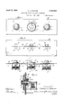
- FIG. 1 is a front elevation of a panel of a radio receiver showing a knob and dial arrangement embodying my invention.
- the tuning condensers are. attached to the rear of the panel as is common practice;
- Fig. 2 is a rear elevational view of the panel showing the rack and pinion mechanism employed in the dial arrangement forming the subject-matter of'this application, this view being substantially a section on the line 22ofFig.3;
- Fig. 3 is a top plan view of the panel and the condensers and controlling devices mounted thereon;
- Fig. 4 is a sectional view of the middle tuning unit and the compound indicating device associated therewith, the section being taken on the line 44 of Fig. 3;
- Fig. 5 is a front elevational view of the panel of a receiver in which a double condenser is employed in place of two single condensers for the second and third tuning units
- Fig. 6 is a top plan view of the same;
- Figs. 7 and 8 are views showing the relative positions of the two parts of the compound indicator with these parts in different relative positions, as will be explained hereinafter;
- Fig. 9 is a fragmentary top plan view showing a lost motion connection which may be employed, if desired, to connect the two racks which connect the compound indicator with the vtwo tuning elements;
- Fig. 10 is anelevational View of the same
- Fig. 11 is an elevational view bf another form of indicator which may be substituted for that shown in the preceding figures;
- Fig. 12 is a top plan View showing a form of this invention in which a double condenser is employed in place of two single condensers and a' compound dial is located between this double condenser and the single condenser;
- Fig. 13 is a sectional view of the line 1313 of- Fig. 12; a
- Fig. 14 shows a modified form of indicator
- Fig. 15 is an elevational view of a form of indicator which may beemployed when it is desired to afford individual control for each condenser instead of interconnecting two of the condensers to operate from one knob;
- Fig. 16 is a sectional view on the line 1616 of Fi 15.
- This shaft has a gear wheel 22 secured thereto and sleeved on this shaft, but turning loosely thereon, is another gear 23.
- These gear wheels ma have metal hubs 24 to facilitate mounting ut the toothed part of the wheel should be of insulating material.
- On the condensers 18 and 18 are secured gear wheels 25 and 26, respectively.
- the knob 21, which is secured on the shaft of the condenser 18 will, of course, operate this condenser.
- This knob also operates the middle condenser 18", this being effected by a connection consisting of a rack bar 27 having teeth 28 on its lower edge which mesh with the teeth of the gear wheels 22 and 26. It will be seen then that the'turning of this knob will cause the dial 15 to revolve and will also cause the condenser 18 and the middle condenser 18 to turn together.
- condenser 18 is provided with a knob 20 secured on its shaft. Meshing with the gear 25 on the shaft of this condenser are teeth 29 on the lower edge of the rack bar 30, this rack bar having another series of teeth 31 on its opposite end which mesh with the freely turning gear 23 which is sleeved loosely on the shaft 19 of the middle condenser, as above stated. It will be seen that the turning of this knob 20 will have no effect upon the condensers 18 and 18 because the gear 23 turns loosely on the shaft 19.
- This gear 23 has its hub 24 elongated to extend toward the front of the panel and connected with this hub in such a way as to be turned with the gear 23 is a disc 32.
- the dial 15 is provided with a sight opening 17, as explained above, it will be seen that a mark placed upon the disc 32 would be visible through the aperture 17 in the 'dial when the disc is turned to the proper position :0 bring this mark into register with the aperure.
- Figs. 7 and 8 the dial and the disc are clearly-shown.
- the white spot 33 is out of register with the opening in the dial, while in F ig. 8 the white spot is nearly in register with the opening in the dial.
- the middle condenser 18 and the condenser 18 are controlled by one knob 21 and that the position of the dial 15 relative to the mark or pointer 34 on the panel 35 will show the position of the movable plates of these two condensers, just as in the case of the sets in common use.
- a compound indicator is afforded, this indicator showing not only the tuning of the second and third condensersbut also the tuning of the first condenser.
- the appearance of the white spot .33 on the disc 32 through the opening 17 in the dial 15 informs the operator that the left-hand condenser is tuned to approximately the same wave length as the other two'condensers.
- the white spot will not ordinarily stand exactly in the center of the opening because of the fact that the condenser 18 is 1 As is well known, the tuning of this circuit is somewhat influenced by the character of anything which is coupled toit. The antenna and the ground connection differ in different locations and types of installation, but it will be found that under all conditions ordinarily met with the white spot will show at least partially through the opening in the dial.
- Suitable guide brackets 36 are provided for holding the racks 27 and 30 in mesh with their respective gears.
- stops 37 are provided on these bars which, when brought against the guide brackets at either end, prevent the bars from moving further and the knobs from being turned.
- the knob 20 will be turned until the numeral 70 registers with the mark 34 on the panel.
- the knob 21 will then be turned until the white spot appears through the opening in the dial.
- the station will then be heard in most cases unless it should be very distant or weak.
- the tuning may then be sharpened to improve the quality or volume by moving the knob 21 slightly one way or the other.
- Figs. 5 and 6 I have shown this invention applied to a. receiver in which the second and third condensers are replaced by a double condenser 38, that is, a construction in which the two condensers are built as a single unit and the two sets of rotor plates 39 mounted on a single shaft 40.
- a single condenser 41 has a knob 42 secured on its shaft 43 and a gear wheel 44 is also secured on the shaft 43 of the condenser 38 behind the panel 45.
- means may be provided whereby the white spot on the disc will be kept always in view through the opening in the dial.
- the left-hand knob may then be adjusted to sharpen tuning.
- the amount of movement of the lefthand knob, independently of the dial and right-hand knob, will be limited and may be sufficient to provide differential tuning between the first circuit and the others.
- a method of coupling the rack bars 27 and 30 together for this purpose is shown.
- One of the bars 27 has formed therein a slot 49 into which projects a pin 50 which is secured in the other bar 30. It will be obvious that if either knob be turned slightly, the rack bar geared thereto will move a short distance when the pin 50 on the one bar will reach the end of the slot 49 in the other bar and this other bar will then be caused to move with the first bar and the condensers will all turn together.
- This lost motion connection may be made in various ways but a satisfactory way is that shown which consists of the slot and pin construction just described.
- a pointer instead of a dial, this pointer working over a scale which is attached to the panel.
- Fig. 11 such a construction is shown.
- the shaft 51 of the condenser carries a pointer 52 which travels over the fixed scale 53 as the condenser is turned.
- This pointer 52 is formed with an opening 54 through which may be seen another pointer 55 which may be connected by means of a rack and loosely mounted gear to an adjustable knob 56, just as the disc 32 is connected in the forms previously described.
- this pointer 55 can be observed through the opening 54 in the large pointer 52 and by this means the location of the lefthand condenser operated by the knob 56 with respect to the other two condensers can be readily determined. If the small pointer 55 stands about midway between the ends of the opening 54 in the large pointer, this would indicate that the individually adjustable condenser stands in about the same position as the two jointly adjustable condensers.
- Fig. 12 shows such an arrangement and it will be seen that this arrangement differs from that shown in Fig. 6 in that in Fig. 6 the knob 48 is secured to the shaft of the double condenser in front of the dial 15.
- the indicator dial 57 is carried by a shaft 58 which may be supported on the panel by a bearing bracket 59.
- the shaft 58 has fixed thereon a gear wheel 60 and a dial 57 is likewise rigidly secured to the shaft so as to turn with it and the gear 60.
- This gear is moved driven by a rack 67 which meshes also with a by a rack 61 which meshes with a gear fixed on the shaft of the double condenser 62 and the dial 57 thus indicates the position of the double condenser.
- Loosely sleeved on the shaft 58 is another gear wheel 63, the hub of which extends forward through the panel and carriesthe disk 64, similar in all respect to the disc 32, previously described.
- the spot 65 on the disc is visible through the opening 66 formed in the dial 57.
- the gear 63 is gear on the shaft of the condenser 68. It will be seen that the operation of tuning the receiver is exactly the same in this case as in the case of the receiver shown and described in connection with Figs. 1 to 4, inclusive.
- Fig. 14 it will be seen that the scale 69 is attached to the panel 70 and the dial 71 has engraved thereon an arrow 72 which may be brought into registry with any of the numbered points on the scale.
- a pointer 7 3 which may be observed through an opening 74 in the dial 71.
- a series of small openings 7 5 may be formed in the dial. This enables the op.- erator of the set to knbw in which direction to turn the knob to bring the pointer opposite the o ening 74.
- the form of my invention shown is adapted for a receiving set in which the three tuning condensers LIG to be individually controlled.
- the middle condenser has its shaft 76 provided with a knob 77 and pointer 78, the knob and pointer being constructed as a unit.
- each bearing a mark such as an arrow-head and these arrow-heads are visible through an opening 81 formed in the pointer 78.
- a gear wheel 82 Sleeved upon the shaft 76 and turning loosely thereon is a gear wheel 82, the hub of which extends through the panel and carries the disc ,7 9.
- another gear 83 Sleeved upon the hub'of this gear and turning loosely thereon. is another gear 83 which extends through the panel and carries on its forward-end the second disc 80.
- the pointer 78 is provided with a scale 84 with the divisions of which the pointer on the disc 80 may be made to register.
- the pointer 78 also carries a mark 85 with which the arrow-head on the disc 79 may be made to register.
- the tuning of the left hand condenser will not always be accomplished by bringing the arrow-head on the disc 79 exactly into registry with the mark 85, but the arrow-head will always be visible through the opening 81 in the pointer.
- the final step in the tuning is, therefore, to turn the knob of the left hand condenser until the arrow-head on the disc 79 shows through the opening 81 in the pointer, and to find the point at which the greatest volume or purest quality of tone is obtained.
- a radio receiving set a front panel, two independently adjustable elements spaced with respect to each other longitudinally of said panel which should occupy definite positions relative to each other for selective wave length reception, two movable indicator members, means for connecting said indicator members with said adjustable elements respectively, said indicator members being located near enough together so as to be conveniently observed together, the path of movement of the two indicator members being such that their relative positions indicates the relative position of the adjustable elements, and a fixed index cooperating with one of said movable indicator members to indicate the absolute position of one of said adjustable elements.
- the combination with two tuning elements rotatably mounted to turn about different axes respectively one of which comprises a condenser having a rotatable shaft, of indicating means for show ing the position of said tuning elements comprising an indicator member mounted on said condenser shaft, a sleeve rotatable on said shaft and connected with one of said tuning elements and an index mounted on said sleeve.
- a radio receiving set the combination with a front panel and two tuning elements spaced with respect to each other longitudinally of said panel, of a compound indicating device comprising two'movableindicating elements adjacent each other, the relative position of which indicates the relative position of the tuning elements, said two movable indicating elements being provided with a lost motion connection therebetween whereby they may be roughly adjusted collecvtively and finally adjusted individually;
- a radio receiving set the combination with two rotatable tuning elements, of a lost motion transmission between said tuning elements, whereby they may be roughly adjusted collectively and finally adjusted individually, said transmission comprising a pair of racks having a lostmotion connection with each other and a pair of pinions rotatable with said tuning elements respectively, and meshing with said racks, respectively.
- a radio receiving set the combination with a front panel and two tuning elements spaced with respect to each other longitudinally of said panel, of a compound indicating device comprising two movable indicating elements adjacent each other, the relative position of which indicates the relative position of the tuning elements, and a fixed indicating device cooperating with one of the movable indicating elements to indicate the absolute position of one of the tuning elements.
- a radio receiving set two condensers mounted to rotate about parallel axes, 1' spectively, a shaft on which one of said condensers is mounted, an indicating member mounted on said shaft to turn therewith, a sleeve on said shaft rotatable independently of said shaft, a second indicating member rotatable with said sleeve, and transmission between the other condenser and said sleeve whereb the indicating member on said sleeve will in icate the position of said other condenser.
- a radio receivin set two manually operable rotatable mem ers, two rotatable tuning elements controlled by said members respectively, two indicating members for indicating the position of said tuning elements respectively, and located so close together that they can be read simultaneously with ease, said manually operable membersbeing so'remote from said indicating members that the hand of the operator in tuning does not obstruct a view of the indicating members, said'manuall operable members being spaced laterally with respect to each other sufli'cient to permit the operator to operate them simultaneously with the right and left hand, respectively.
- a radio receiving set two manually operable rotatable members, two rotatable tuning elements controlled by said members respectively, two indicating members for indicatin the position of said tuning elements respectively and located so close together that they can be read simultaneously with ease, said manually operable members being so remote from said indicating members that the hand of the operator in tuning does not obstruct a view of the indicating members, said manually operable members being spaced laterally with respect to each other suflicient to permit the operator to operate them simultaneously with the right and left hand, respectively, and mounted on opposite sides of said indicating members.
- a front panel two manually operable rotatable members, two rotatable tuning elements controlled by said members respectively, two indicating members for indicating the position of said tuning elements respectively, and located so close together that they can be read simultaneously with ease, said manually operable members being so remote from said indicating members that the hand of the operator in tuning does not obstruct a view of the indicating members, said manually operable members being spaced with respect to each other longitudinally of said panel;
- a lost motion transmission between said tuning elements whereby they may be roughl adjustable collectively and finally. adjusta le individually, said transmission comprising a pair of arms for respectively operating said two tuning elements, said pair of arms having a lost motion connection with each other.
Landscapes
- Structure Of Receivers (AREA)
Description
April 15, 1930.
C. L. HOPKINS INDICATING DEVICE FOR RADIO RECEIVERS Filed Sept. 16, 1925 3 Sheets-Sheet l (76' 7 J6 s la 91 4 K e 8' 7 Q 64 W 6, 49 50 9 I w 40 54 i? 25 April 15, 1930. c. L. HOPKINS INDICATING DEVI CE FOR RADIO RECEIVERS Filed Se t. 16, 1925 3 Sheets-Sheet 2 April 15, 1930. c. L. HOPKINS 1,754,792
INDICATING DEVICE FOR RADIO RECEIVERS Filed Sept. 16, 1925 x 3 Sheets-Sheet 3 Patented Apr. 15, 1930 UNITED STATES PATENT OFFICE CHARLES L. HOPKINS, OF RIVER FOREST, ILLINOIS, ASSIGNOR TO BENJAMIN ELECTRIC MANUFACTURING COMPANY, OF CHICAGO, ILLINOIS, A CORPORATION OF ILLINOIS INDICATING DEVICE FOR RADIO RECEIVERS Application filed September In radio receivers it is common practice to employ three or more tuning condensers, each of which tunes a circuit, including in ductance and the. capacity of the condenser.
In a very familiar type of receiver two stages of tuned radio frequency amplification are employed in combination with a tuned detector circuit and two stages of audio frequency amplification. In such a set the input or grid circuits of the radio frequency amplifiers and the input or grid circuit of the detector are tuned by identical condensers. In the usual construction the shaft of each condenser carries a dial and a 'knob is provided for each dial; this knob usually being constructed as apart of the dial. In such a receiver it will be found that the second and third dials will read practically alike for all wave lengths to which the set can be tuned but the dial of the first condenser will usually not read the same as the other two dials. The reasons for this are well understood and need not be discussed here. In order to simplify the method of finding stations it has been proposed to interconnectby suitable mechanical means the second and third condensers and thus to tune the receiver by the use of two hand operative controls and two dials. I Attempts have been made to reduce to reduce the number of controls to a single control by mechanically connecting all of the condensers but when this is done it is necessary to provide a separate condenser of small capacity and connect this across the first condenser or in parallel therewith. In such a set, when the station to which the set is to be tuned has been found, the sharpness of the tuning can be improved by the manipulation of the small supplementary condenser mentioned.
As is well known, two condensers connectcd in parallel are not as eflicient as one condenser having the. same capacity as the two condensers so connected together ber cause of the fact that the supporting strips or parts of dielectric material used for insulation and other mechanical parts and features employed in the construction of the condensers are multiplied and as these parts introduce losses and also addto the minimum 16, 1925. Serial No. 56,623.
the disadvantages which would result from the use of another smaller condenser to vary the capacity of the first condenser after it has been roughly tuned. It may be stated in other language that the object of this invention is to provide an arrangement which will enable an unskilled person to tune the set to a desired station with the utmost facility and yet permit the manufacturer to incorporate in the set the desired number of tuned circuits. It is believed that this arrangement provides a means whereby none of the electrical efliciency of'the receiver need be sacrificed in order to simplify the tuning and handling of the set by the user and yet provides the simplicity in tuning which is secured by the use of a single knob and dial.
In a receiver constructed accordin to this o c I n c present invention, there is a slngle dial but.
there are two controlling knobs and these knobs may be somewhat removed from the dial so as to leave the latter free of any knobs or the like which would obstruct the view or distract the attention of the operator from the dial.
In the drawings, in which my invention is illustrated- Figure 1 is a front elevation of a panel of a radio receiver showing a knob and dial arrangement embodying my invention. In this receiver the tuning condensers are. attached to the rear of the panel as is common practice;
Fig. 2 is a rear elevational view of the panel showing the rack and pinion mechanism employed in the dial arrangement forming the subject-matter of'this application, this view being substantially a section on the line 22ofFig.3;
Fig. 3 is a top plan view of the panel and the condensers and controlling devices mounted thereon;
Fig. 4 is a sectional view of the middle tuning unit and the compound indicating device associated therewith, the section being taken on the line 44 of Fig. 3;
Fig. 5 is a front elevational view of the panel of a receiver in which a double condenser is employed in place of two single condensers for the second and third tuning units Fig. 6 is a top plan view of the same;
Figs. 7 and 8 are views showing the relative positions of the two parts of the compound indicator with these parts in different relative positions, as will be explained hereinafter;
Fig. 9 is a fragmentary top plan view showing a lost motion connection which may be employed, if desired, to connect the two racks which connect the compound indicator with the vtwo tuning elements;
Fig. 10 is anelevational View of the same;
Fig. 11 is an elevational view bf another form of indicator which may be substituted for that shown in the preceding figures;
Fig. 12 is a top plan View showing a form of this invention in which a double condenser is employed in place of two single condensers and a' compound dial is located between this double condenser and the single condenser;
Fig. 13 is a sectional view of the line 1313 of- Fig. 12; a
Fig. 14 shows a modified form of indicator;
Fig. 15 is an elevational view of a form of indicator which may beemployed when it is desired to afford individual control for each condenser instead of interconnecting two of the condensers to operate from one knob; and
Fig. 16 is a sectional view on the line 1616 of Fi 15.
Re erring first to the form of my invention shown in Figs. 1 to 4, inclusive, it will be seen that in place of the familiar panel bearing a In'ultiplicit of dials, I provide a single dial 15 having the usual scale 16 extending around 180 of its circumference. This dial is formed with an aperture 17. On the rear of the panel the tuning condensers 18 18 and 18 are supported in any suitable manner and a shaft 19 for each condenser extends through the panel as usual. On the shaft 19 of the condenser 18* is arranged a knob 20 and on the shaft 19 of the condenser 18 is secured a knob 21. On the shaft 19 of the middle condenser 18 is secured the dial 15. This shaft has a gear wheel 22 secured thereto and sleeved on this shaft, but turning loosely thereon, is another gear 23. These gear wheels ma have metal hubs 24 to facilitate mounting ut the toothed part of the wheel should be of insulating material. On the condensers 18 and 18 are secured gear wheels 25 and 26, respectively. The knob 21, which is secured on the shaft of the condenser 18 will, of course, operate this condenser. This knob also operates the middle condenser 18", this being effected by a connection consisting of a rack bar 27 having teeth 28 on its lower edge which mesh with the teeth of the gear wheels 22 and 26. It will be seen then that the'turning of this knob will cause the dial 15 to revolve and will also cause the condenser 18 and the middle condenser 18 to turn together.
As stated above condenser 18 is provided with a knob 20 secured on its shaft. Meshing with the gear 25 on the shaft of this condenser are teeth 29 on the lower edge of the rack bar 30, this rack bar having another series of teeth 31 on its opposite end which mesh with the freely turning gear 23 which is sleeved loosely on the shaft 19 of the middle condenser, as above stated. It will be seen that the turning of this knob 20 will have no effect upon the condensers 18 and 18 because the gear 23 turns loosely on the shaft 19. This gear 23 has its hub 24 elongated to extend toward the front of the panel and connected with this hub in such a way as to be turned with the gear 23 is a disc 32.
As the dial 15 is provided with a sight opening 17, as explained above, it will be seen that a mark placed upon the disc 32 would be visible through the aperture 17 in the 'dial when the disc is turned to the proper position :0 bring this mark into register with the aperure.
It has been found that if the dial is black with white markings and the disc behind the dial is also black with a round white spot 33, this spot may be very distinctly seen against the black background of the disc and as the disc is turned back and forth to carry the white spot past the aperture it is very easily seen.
In Figs. 7 and 8 the dial and the disc are clearly-shown. In Fig. 7 the white spot 33 is out of register with the opening in the dial, while in F ig. 8 the white spot is nearly in register with the opening in the dial.
It will be seen that the middle condenser 18 and the condenser 18 are controlled by one knob 21 and that the position of the dial 15 relative to the mark or pointer 34 on the panel 35 will show the position of the movable plates of these two condensers, just as in the case of the sets in common use. It will be seen that with the dial arrangement illustrated, a compound indicator is afforded, this indicator showing not only the tuning of the second and third condensersbut also the tuning of the first condenser. The appearance of the white spot .33 on the disc 32 through the opening 17 in the dial 15 informs the operator that the left-hand condenser is tuned to approximately the same wave length as the other two'condensers. The white spot will not ordinarily stand exactly in the center of the opening because of the fact that the condenser 18 is 1 As is well known, the tuning of this circuit is somewhat influenced by the character of anything which is coupled toit. The antenna and the ground connection differ in different locations and types of installation, but it will be found that under all conditions ordinarily met with the white spot will show at least partially through the opening in the dial.
Suppose now it be desired to tune in a station which is known to correspond to the number 70 on the dial, as shown in Fig. 8; the knob 20 will be turned until the numeral 70 registers with the mark 34 on the panel. The knob 21 will then be turned until the white spot appears through the opening in the dial. The station will then be heard in most cases unless it should be very distant or weak. The tuning may then be sharpened to improve the quality or volume by moving the knob 21 slightly one way or the other.
In Figs. 5 and 6, I have shown this invention applied to a. receiver in which the second and third condensers are replaced by a double condenser 38, that is, a construction in which the two condensers are built as a single unit and the two sets of rotor plates 39 mounted on a single shaft 40. Such condensers are well known and need not be described in detail. In this form of my invention, the single condenser 41 has a knob 42 secured on its shaft 43 and a gear wheel 44 is also secured on the shaft 43 of the condenser 38 behind the panel 45. A
' rack bar 46 connectsthis gear wheel to anbe seen that the method of tuning a set employing this construction, is exactly the same as that in which three separate condensers are arranged on the back of the panel. In the case of the double condenser, however, the knob 48 and dial. 15 may be combined as shown in Figs. 5 and 6. g
If desired, means may be provided whereby the white spot on the disc will be kept always in view through the opening in the dial. When such a construction is employed, the
turning of either of the two knobs will move all of the condensers. After the dial has been moved to the desired position after tuning in a particular station, the left-hand knob may then be adjusted to sharpen tuning. In this case, the amount of movement of the lefthand knob, independently of the dial and right-hand knob, will be limited and may be sufficient to provide differential tuning between the first circuit and the others.
In Fig. 9, a method of coupling the rack bars 27 and 30 together for this purpose is shown. One of the bars 27 has formed therein a slot 49 into which projects a pin 50 which is secured in the other bar 30. It will be obvious that if either knob be turned slightly, the rack bar geared thereto will move a short distance when the pin 50 on the one bar will reach the end of the slot 49 in the other bar and this other bar will then be caused to move with the first bar and the condensers will all turn together. This lost motion connection may be made in various ways but a satisfactory way is that shown which consists of the slot and pin construction just described.
In some cases it may be preferred to use a pointer instead of a dial, this pointer working over a scale which is attached to the panel. In Fig. 11 such a construction is shown. In this case the shaft 51 of the condenser carries a pointer 52 which travels over the fixed scale 53 as the condenser is turned. This pointer 52 is formed with an opening 54 through which may be seen another pointer 55 which may be connected by means of a rack and loosely mounted gear to an adjustable knob 56, just as the disc 32 is connected in the forms previously described. It will be seen that this pointer 55 can be observed through the opening 54 in the large pointer 52 and by this means the location of the lefthand condenser operated by the knob 56 with respect to the other two condensers can be readily determined. If the small pointer 55 stands about midway between the ends of the opening 54 in the large pointer, this would indicate that the individually adjustable condenser stands in about the same position as the two jointly adjustable condensers.
In some cases it may be thought desirable to employ a twin condenser in place of a second and third condenser and to separate the indicator from both of the knobs. Fig. 12 shows such an arrangement and it will be seen that this arrangement differs from that shown in Fig. 6 in that in Fig. 6 the knob 48 is secured to the shaft of the double condenser in front of the dial 15. In Fig. 12 the indicator dial 57 is carried by a shaft 58 which may be supported on the panel by a bearing bracket 59. The shaft 58 has fixed thereon a gear wheel 60 and a dial 57 is likewise rigidly secured to the shaft so as to turn with it and the gear 60. This gear is moved driven by a rack 67 which meshes also with a by a rack 61 which meshes with a gear fixed on the shaft of the double condenser 62 and the dial 57 thus indicates the position of the double condenser. Loosely sleeved on the shaft 58 is another gear wheel 63, the hub of which extends forward through the panel and carriesthe disk 64, similar in all respect to the disc 32, previously described. The spot 65 on the disc is visible through the opening 66 formed in the dial 57. The gear 63 is gear on the shaft of the condenser 68. It will be seen that the operation of tuning the receiver is exactly the same in this case as in the case of the receiver shown and described in connection with Figs. 1 to 4, inclusive.
. Referring to Fig. 14 it will be seen that the scale 69 is attached to the panel 70 and the dial 71 has engraved thereon an arrow 72 which may be brought into registry with any of the numbered points on the scale. In place of the disc 32 carrying the white spot 33 there may be employed a pointer 7 3 which may be observed through an opening 74 in the dial 71. In order that the position of this pointer with respect to the dial may be seen at all times, a series of small openings 7 5 may be formed in the dial. This enables the op.- erator of the set to knbw in which direction to turn the knob to bring the pointer opposite the o ening 74.
' Re erring to Figs. 15 and 16, the form of my invention shown is adapted for a receiving set in which the three tuning condensers LIG to be individually controlled. In this form the middle condenser has its shaft 76 provided with a knob 77 and pointer 78, the knob and pointer being constructed as a unit.
Behind this pointer are two discs 79 and 80,
each bearing a mark such as an arrow-head and these arrow-heads are visible through an opening 81 formed in the pointer 78. Sleeved upon the shaft 76 and turning loosely thereon is a gear wheel 82, the hub of which extends through the panel and carries the disc ,7 9. Sleeved upon the hub'of this gear and turning loosely thereon. is another gear 83 which extends through the panel and carries on its forward-end the second disc 80.
The pointer 78 is provided with a scale 84 with the divisions of which the pointer on the disc 80 may be made to register. The pointer 78 also carries a mark 85 with which the arrow-head on the disc 79 may be made to register.
on the disc 80 with respect to the scale 84 will always be the same for a given wave length regardless of the type of antennae employed, but this is not true in'regard to the position of the disc 79 with respect to the mark 85. For this reason the tuning of the left hand condenser will not always be accomplished by bringing the arrow-head on the disc 79 exactly into registry with the mark 85, but the arrow-head will always be visible through the opening 81 in the pointer. The final step in the tuning is, therefore, to turn the knob of the left hand condenser until the arrow-head on the disc 79 shows through the opening 81 in the pointer, and to find the point at which the greatest volume or purest quality of tone is obtained.
I claim: 1. In a radio receiving set, a front panel, two independently adjustable elements spaced with respect to each other longitudinally of said panel which should occupy definite positions relative to each other for selective wave length reception, two movable indicator members, means for connecting said indicator members with said adjustable elements respectively, said indicator members being located near enough together so as to be conveniently observed together, the path of movement of the two indicator members being such that their relative positions indicates the relative position of the adjustable elements, and a fixed index cooperating with one of said movable indicator members to indicate the absolute position of one of said adjustable elements.
2. The combinationwith a front panel and two tuning units spaced with respect to each other longitudinall of the panel, of a movable indicator provi ed with a scale for showing the position of one of the tuning units, and movable means for showing the position of the second tuning unit, said means reading on the movable indicator and mechanical connections between said movable means and said second tuning unit.
3. In a radio receiving set, the combination with two tuning elements rotatably mounted to turn about different axes respectively, one of which comprises a condenser having a rotatable shaft, of indicating means for show ing the position of said tuning elements comprising an indicator member mounted on said condenser shaft, a sleeve rotatable on said shaft and connected with one of said tuning elements and an index mounted on said sleeve.
4. The combination with a front panel and two tuning units spaced laterally with respect to each other longitudinally of said panel, of two movable indicators, one behind the other, one of said indicators being pro vided with a scale whereby the position of be ascertained, the other indicator showing the position of the other tuning unit and reading upon the first indicator.
5. In a radio receiving set, the combination with a front panel and two tuning elements spaced with respect to each other longitudinally of said panel, of a compound indicating device comprising two'movableindicating elements adjacent each other, the relative position of which indicates the relative position of the tuning elements, said two movable indicating elements being provided with a lost motion connection therebetween whereby they may be roughly adjusted collecvtively and finally adjusted individually;
6. In a radio receiving set, the combination with two rotatable tuning elements, of a lost motion transmission between said tuning elements, whereby they may be roughly adjusted collectively and finally adjusted individually, said transmission comprising a pair of racks having a lostmotion connection with each other and a pair of pinions rotatable with said tuning elements respectively, and meshing with said racks, respectively.
7. In a radio receiving set, the combination with a front panel and two tuning elements spaced with respect to each other longitudinally of said panel, of a compound indicating device comprising two movable indicating elements adjacent each other, the relative position of which indicates the relative position of the tuning elements, and a fixed indicating device cooperating with one of the movable indicating elements to indicate the absolute position of one of the tuning elements.
8. In a radio receiving set, two condensers mounted to rotate about parallel axes, 1' spectively, a shaft on which one of said condensers is mounted, an indicating member mounted on said shaft to turn therewith, a sleeve on said shaft rotatable independently of said shaft, a second indicating member rotatable with said sleeve, and transmission between the other condenser and said sleeve whereb the indicating member on said sleeve will in icate the position of said other condenser.
9. In a radio receivin set, two manually operable rotatable mem ers, two rotatable tuning elements controlled by said members respectively, two indicating members for indicating the position of said tuning elements respectively, and located so close together that they can be read simultaneously with ease, said manually operable membersbeing so'remote from said indicating members that the hand of the operator in tuning does not obstruct a view of the indicating members, said'manuall operable members being spaced laterally with respect to each other sufli'cient to permit the operator to operate them simultaneously with the right and left hand, respectively.
10. In a radio receiving set, two manually operable rotatable members, two rotatable tuning elements controlled by said members respectively, two indicating members for indicatin the position of said tuning elements respectively and located so close together that they can be read simultaneously with ease, said manually operable members being so remote from said indicating members that the hand of the operator in tuning does not obstruct a view of the indicating members, said manually operable members being spaced laterally with respect to each other suflicient to permit the operator to operate them simultaneously with the right and left hand, respectively, and mounted on opposite sides of said indicating members.
11. In a radi'oreceiving set, a front panel, two manually operable rotatable members, two rotatable tuning elements controlled by said members respectively, two indicating members for indicating the position of said tuning elements respectively, and located so close together that they can be read simultaneously with ease, said manually operable members being so remote from said indicating members that the hand of the operator in tuning does not obstruct a view of the indicating members, said manually operable members being spaced with respect to each other longitudinally of said panel;
12. In a, radio receiving set, thecombination with-a front panel and two tuning elements spaced with respect to each other longitudinally of said panel, of a lost motion transmission between said tuning elements, whereby they may be roughl adjustable collectively and finally. adjusta le individually, said transmission comprising a pair of arms for respectively operating said two tuning elements, said pair of arms having a lost motion connection with each other.
In witness whereof, I have hereunto subscribed my name.
CHARLES L. HOPKINS
Priority Applications (1)
| Application Number | Priority Date | Filing Date | Title |
|---|---|---|---|
| US56623A US1754792A (en) | 1925-09-16 | 1925-09-16 | Indicating device for radio receivers |
Applications Claiming Priority (1)
| Application Number | Priority Date | Filing Date | Title |
|---|---|---|---|
| US56623A US1754792A (en) | 1925-09-16 | 1925-09-16 | Indicating device for radio receivers |
Publications (1)
| Publication Number | Publication Date |
|---|---|
| US1754792A true US1754792A (en) | 1930-04-15 |
Family
ID=22005617
Family Applications (1)
| Application Number | Title | Priority Date | Filing Date |
|---|---|---|---|
| US56623A Expired - Lifetime US1754792A (en) | 1925-09-16 | 1925-09-16 | Indicating device for radio receivers |
Country Status (1)
| Country | Link |
|---|---|
| US (1) | US1754792A (en) |
-
1925
- 1925-09-16 US US56623A patent/US1754792A/en not_active Expired - Lifetime
Similar Documents
| Publication | Publication Date | Title |
|---|---|---|
| US2501274A (en) | Time control device | |
| US1754792A (en) | Indicating device for radio receivers | |
| US2062379A (en) | Radio receiver | |
| US3376846A (en) | Indicating apparatus | |
| US1919043A (en) | Indicating mechanism | |
| US2636981A (en) | Automatic radio dialing device | |
| US2078637A (en) | Radio tuning device | |
| US1704754A (en) | Radio apparatus and method of operating the same | |
| US2129756A (en) | Radio apparatus | |
| US2067871A (en) | Tuning device for radio sets | |
| US2824957A (en) | Very high frequency television tuner having an ultra high frequency adapter | |
| US1582555A (en) | Device for controlling and indicating the tuning of radio instruments and the like | |
| US2078031A (en) | Dial mechanism | |
| US1863050A (en) | Radio filter apparatus | |
| US1707948A (en) | Tuning system | |
| US2493746A (en) | Shorting system for radio coils | |
| US1853039A (en) | Uni-control tuning apparatus | |
| DE578921C (en) | Arrangement for high frequency receivers | |
| US1876287A (en) | Radio apparatus | |
| US1708539A (en) | Radio receiving apparatus | |
| US2139451A (en) | Dial for radio apparatus | |
| US1670272A (en) | Radio dial construction | |
| US2028137A (en) | Tuning arrangement for radio receiving sets | |
| US2094751A (en) | Tuning means for receiver sets | |
| US1685803A (en) | Logging and indicating device for radio receiving sets |