US1754323A - Color-projection apparatus for cinematographs - Google Patents
Color-projection apparatus for cinematographs Download PDFInfo
- Publication number
- US1754323A US1754323A US633433A US63343323A US1754323A US 1754323 A US1754323 A US 1754323A US 633433 A US633433 A US 633433A US 63343323 A US63343323 A US 63343323A US 1754323 A US1754323 A US 1754323A
- Authority
- US
- United States
- Prior art keywords
- shutter
- color
- spindle
- standard
- casing
- Prior art date
- Legal status (The legal status is an assumption and is not a legal conclusion. Google has not performed a legal analysis and makes no representation as to the accuracy of the status listed.)
- Expired - Lifetime
Links
- 239000003086 colorant Substances 0.000 description 4
- 241001112867 Jafar Species 0.000 description 1
- 238000010276 construction Methods 0.000 description 1
- 230000008878 coupling Effects 0.000 description 1
- 238000010168 coupling process Methods 0.000 description 1
- 238000005859 coupling reaction Methods 0.000 description 1
- 230000000694 effects Effects 0.000 description 1
- 239000000314 lubricant Substances 0.000 description 1
- 230000000873 masking effect Effects 0.000 description 1
- 238000000034 method Methods 0.000 description 1
- 230000002035 prolonged effect Effects 0.000 description 1
- 230000010349 pulsation Effects 0.000 description 1
- 230000000717 retained effect Effects 0.000 description 1
Images
Classifications
-
- G—PHYSICS
- G03—PHOTOGRAPHY; CINEMATOGRAPHY; ANALOGOUS TECHNIQUES USING WAVES OTHER THAN OPTICAL WAVES; ELECTROGRAPHY; HOLOGRAPHY
- G03B—APPARATUS OR ARRANGEMENTS FOR TAKING PHOTOGRAPHS OR FOR PROJECTING OR VIEWING THEM; APPARATUS OR ARRANGEMENTS EMPLOYING ANALOGOUS TECHNIQUES USING WAVES OTHER THAN OPTICAL WAVES; ACCESSORIES THEREFOR
- G03B33/00—Colour photography, other than mere exposure or projection of a colour film
- G03B33/08—Sequential recording or projection
Definitions
- the object of this invention is to provide an improved color projection apparatus for cinematographs which is specially suitable for application to existing or ordinary cine- 5 matographic projection apparatus without change in design of the latter.
- This invention consists in an attachment adapted to be fitted to the spindle of a standard cinematographic projector comprising lo gearing driven by the spindle and a color shutter operated thereby at an appropriate speed said shutter being used alone or in conjunction with a standard shutter mounted on the spindle.
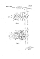
- Figs. 1 and 2 bein a plan view and a sectional elevation respectively of the shutter mechanism.
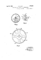
- Fig. 3 1s an end view showing the epicyclic gear used for operating one or both shutters.
- j Fig. 4 is an end view showing the method of securing the shutter mechanism to the bracket of a projector.
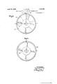
- Fi 5 is an elevation Y showing both standard an color shutters.
- Fig. 6 is a similar view of the color shutter alone and Fig. 7 is a combined color and ordinary shutter. ⁇ V
- illustrated 1 represents the shaft Of'an ordinary projector which is carried in a bearing formed in a 'bracket 2.
- this bracket 1 In order to secure m improved .shutter fitting to this bracket 1. provide a member 3 into which the end of the bracket extends, relative movement .between the member and bracket being prevented in any convenient manner as for exam le'by roviding an end piece 4 for the mem r 3 aving an aperture 5 shaped so as to permit of the entrance of the end of the bracket 2. It will'be understood the shape of aperture 5 will not always be the same as diiferent standard projectors have different shaped brackets.
- the mem- Eer 3 may be secured directly to the casing ofthe projector in an convenient manner as for example by provi the member with a flange which can be secured to the casin by means of screws or bolts.
- set screw 6 serves to hold the bracktended to correct for streamin et 2 and member 3 in their relative positions;
- a small tube 7 is rigidly secured on the pe.
- riphery of the member 3 and' contains a spring pressed plunger 8 adapted to engage a iiange 10 carried on the periphery of a cupshaped member 11 which surrounds a cylindrical portion of member 3 and is capable of rotary motion relatively thereto.
- the members 3 and llwheu in working relationship constitute an elastic frictional coupling.
- a ⁇ groove or slot 12 is formed in member 3 through or into which a projection 13 carried by a handle 14 projects.
- the handle is screwed into the member 11 and by turning the handle with 'suicient force to overcome the friction of the plunger 8 on flange 10 the member 11 and the parts secured thereto can be rotated relativel to the member 3 through a distance depending on the length of slot 12.
- This slot may extend round a quarter of the circumference when the gearing driving the shutter is 4 to v1, as in the example. illustrated.
- the length of the slot however is determined ⁇ by the ratio of the gearing but it may be further ex- ⁇ when a combination shutter such as hereinafter de# scribed is used if the machine is in operation with the shutter improperly set in relation to theA film.
- a sleeve 15 Surrounding the shaft or spindle ⁇ 1 is a sleeve 15 carrying a radiallyextending plate 15 on which is mounted a pinion 16.A The member 11 is secured to this sleeve 15 by means of a set screw 19 so that the position of plate 15 may be varied by turning the handle 14.
- the standard shutter 17 1s secured directly to the spindle 1 when the shutter construction permltsof this and the color shutter 18 is mounted in close proximity thereto on a tubulz r member adapted to rotate on a sleeve 20 surrounding the spindle 1 and secured thereto by a srew 21.
- a pinion 20 On the inner end of sleeve 20 1s a pinion 20 adapted to gear with the pinion 16.
- a c 22 having an internal gear wheel 22 cut ⁇ 1n it, thls gearV wheel being adapted to mesh with thepinion 1'6.
- the casing 22 is closed by means of a plate or disc 23 having a tubular member or sleeve formed integral or secured to it on which the color shutter is carried.
- the disc 23 may be screwed into the casing 22 and fixed relatively theretolby means o a screw 24.
- an oil conduit provided with a screw cap'is provided so that oil or other lubricant can be inserted into the casing.
- the spindle 1 does not extend beyond the machine casing to permit of the standard shutter being mounted on it after the mechanism just described has been fitted in place and in this case I extend the tubular member 20 a suiiicient distance to take the shutter.
- this member 20 is fixed to the spindle 1 by means of the screw 21 it will rotate at the saine s eed as the spindle and therefore the speed o the shutter will be the same as if it were mounted directly on the spindle.
- the o ration of the mechanism is as follows: en a film is in place and the.pro]ec tor driving mechanism is in operation thc standard shutter 17 rotates aty the speed of spindle 1. As the sleeve 20 is secured to the spindle, this sleeve with pinion 20 will also rotate at the same s ed as the spindle 1. The pinion 16 with w ich pinion 20' meshes is held against rotation about the axis of spindle 1 by means of plate 15 and therefore the motion of pinion 20' will be transmitted through 16 to the internal wheel 22 and this wheel and its casing 22 and disc 23 with the color shutter mounted on its sleeve will rotate at a speed depending on the number of teeth on the wheel and pinions.
- the gearing that the speed of the shut-ter is a third or a quarter that of the standard shutter but the exact relative speeds of the two shutters forms no part of tlie present invention.
- the ring is designed so that the color shutter will rotate at a quarter the speed of the standard shutter and in the opposite direction.
- the two shutters may be made to rotate in the same direction by mountv ing a second pinion on plate 15' transmitting the motion from pinion 20 to pinion'16.
- the handle 14 is rotated through a quarter ofv 'a lrevolution when .the shutters have a four to one speed ratio.
- This rotation of the handle 14 causes a corresponding rotation of the plate 15' carrying 16 which in turn causes-the wheel 22' to or lose one quarter of a revolution relatively to the spindle 1 and the Stlndlld Shutter 17.
- Fig. 5 shows the standard and color shutters tion shutter in which the apertures are pro- -vided with alternatered and blue green filters 29 and 30 respectively separated by masking blades 26.
- the filters are the saine length but as the blue green effect is retained longer by the eye than the red it is preferable to cut down the duration of the time the picture is projected through these filters and this may be done by providing a central flicker blade 27 on each blue green filter 30, or by cutting down the length of the filter by inserting a flicker blade 28 at each end. These flicker blades serve to minimize pulsation.
- the standard shutter When a color picture is to .be shown the standard shutter is removed and the combination shutter secured to the sleeve of plate 23 and the standard spindle is utilized to drive this shutter at the appropriate speed depending on the ratio of the gears used. It will thusj be seen that the same machine may be used for projecting black and white pictures by the use of a standard shutter only or for projecting color pictures either by the use of a standard shutter running at the usual speed and a color shutter running at a speed proportionalto the standard shutter or by the use of a combination shutter driven through the gearing at a speed proportional to, but slower than the standard spindle.
- an attachnient therefor comprising, a stationary sleeve member, an angularly adjustable cup-shaped member frictionally engagingsaid sleeve, an intermediateigear, an intermediate gear support secured to .the cup-shaped member on which the intermediate gear turns, a driving gear on said spindle meshing with the intermediate gear, a driven gear meshing with the' intermediate gear, an enclosing casing for the gears secured to and revolving with said driven gear, a shutter secured to the casing. and manual means carried by the cup-shaped member for adjusting the position thereof' to vary the angular position of the intermediate gear support to position the openings in the shutters.
- a color projection attachment for standard cinematographic devices having a frame, a revoluble spindle and the usual shutter, comprising a securing member for attachment to said frame, a casing revolubly mounted on said spindle-and carrying a color screen rotating in juxtaposition to said shutter and cooperating therewith, and a geared driving connectionffrom said spindle to and within said casing to maintain the proper speedand phase relation between said shutter and said color screen in accordance with the number of colors being projected and the speed of the shutter with respect to the film.
- a color projection attachment for standard cinematographic devices having a frame, a revoluble spindle and the usual shutter, comprising a securing member for engaging said frame, a casing revolubly mounted on said spindle and carrying a color screen rotating in juxtaposition to said shutter and cooperating therewith, and a geared driving connection, having a movable intermediate gear, from said spindle to and within said casing to maintain the proper speed relation between said shutter and said c'olor screens in accordance with the number of colors being projected and the speed ofthe shutter with respect to the film, an intermediate gear of said driving connection being adjustably supported from said frame to vary the phase relation between said shutter and' said color screen.
- a color projection vattachment for standard.cinematographic devices having a frame. a revoluble spindle andthe usual shutter. comprising a securing member for engaging said frame, a casing revolubly mounted on said spindle and carrying a color screen rotating in juxtaposition to said shutter and cooperating therewith, and a geared driving comm-tion between said spindle and color screen to maintain the proper speed relation between said shutter and sa1d color screen in accordance with the number of colors being projected.
- connection comprising an internal gear on said casing, a pinion fixed to said spindle, and an intermediate gear meshing with said internal gear and said pinion, adjustably supported from said frame to vary the phase relation between said shutter and said color screen.
Landscapes
- Physics & Mathematics (AREA)
- General Physics & Mathematics (AREA)
- Shutters For Cameras (AREA)
Description
R. KILLICK April 15, 1930.
COLOR PROJECTION APPARATUS FOR CINEMATOGRAPHS l t e e M S .t wl 1 1 h f s 8 E 1,. 1 Qu 3. 2 2 9 1 2 4. 2 2 w 9% U m, 1 w 2 14 1 1 l Al .l l||||.| 1 BW: F 3 IGH... P /v 6 2L7 1t 4 8 wm f l SMV 1 w. 2 22 mi '2 f 2 f 2 l 2 .9 0 5 5 M1 52 1. 2 1 o 2 g :l 4 F. 1
Re g in n1 K'L'uck y Jafar/7W.
April 15, 1930. R. KILLICK 1,754,323
COLOR PROJECTION APPARATUS FOR CINEMATOGRPHS Filed April 20, 1923 3 Sheets-Sheet 2 Rgnal muck,
April 15, l19.30'. R, KlLLlCK 1,754,323
COLOR PROJECTION APPARATUS 'FoR- CINEMATOGRAPHS Filed April 20, 1923 `3 Sheets-Sheet f3 IN VEA/70K Mlm, MMM Z/V Attorney.
Patented Apr. Y', 1930 i UNITED` STATES 4PATENT OFFICE xILLTcx, or LoNnoN, ENGLAND, AssroNon. To THE x. a si sYNnIcA'rE Lnrrrxn, or LONDON, ENGLAND, A BRITISH COMPANY t COLOR-PROJECTION APPARATUS FOR CINELIATOGRAPHS Application led April 20, 1923, Serial No. 633,433, and in Great Britain .Tune 26, 1923.
The object of this invention is to provide an improved color projection apparatus for cinematographs which is specially suitable for application to existing or ordinary cine- 5 matographic projection apparatus without change in design of the latter.
' This invention consists in an attachment adapted to be fitted to the spindle of a standard cinematographic projector comprising lo gearing driven by the spindle and a color shutter operated thereby at an appropriate speed said shutter being used alone or in conjunction with a standard shutter mounted on the spindle.
The accompanying drawings illustrate my invention, Figs. 1 and 2 bein a plan view and a sectional elevation respectively of the shutter mechanism. Fig. 3 1s an end view showing the epicyclic gear used for operating one or both shutters. y
j Fig. 4 is an end view showing the method of securing the shutter mechanism to the bracket of a projector. Fi 5 is an elevation Y showing both standard an color shutters.
Fig. 6 isa similar view of the color shutter alone and Fig. 7 is a combined color and ordinary shutter. `V
In the form of my invention illustrated 1 represents the shaft Of'an ordinary projector which is carried in a bearing formed in a 'bracket 2. In order to secure m improved .shutter fitting to this bracket 1. provide a member 3 into which the end of the bracket extends, relative movement .between the member and bracket being prevented in any convenient manner as for exam le'by roviding an end piece 4 for the mem r 3 aving an aperture 5 shaped so as to permit of the entrance of the end of the bracket 2. It will'be understood the shape of aperture 5 will not always be the same as diiferent standard projectors have different shaped brackets. In some standard types of projector there is no rojecting bracket and in such cases the mem- Eer 3 may be secured directly to the casing ofthe projector in an convenient manner as for example by provi the member with a flange which can be secured to the casin by means of screws or bolts. In the examp e il- 5 lustrated set screw 6 serves to hold the bracktended to correct for streamin et 2 and member 3 in their relative positions; A small tube 7 is rigidly secured on the pe. riphery of the member 3 and' contains a spring pressed plunger 8 adapted to engage a iiange 10 carried on the periphery of a cupshaped member 11 which surrounds a cylindrical portion of member 3 and is capable of rotary motion relatively thereto. The members 3 and llwheu in working relationship constitute an elastic frictional coupling. To hold members 3 and 11 in their relative longitudinal positions a` groove or slot 12 is formed in member 3 through or into which a projection 13 carried by a handle 14 projects.
The handle is screwed into the member 11 and by turning the handle with 'suicient force to overcome the friction of the plunger 8 on flange 10 the member 11 and the parts secured thereto can be rotated relativel to the member 3 through a distance depending on the length of slot 12. This slot may extend round a quarter of the circumference when the gearing driving the shutter is 4 to v1, as in the example. illustrated. The length of the slot however is determined`by the ratio of the gearing but it may be further ex- `when a combination shutter such as hereinafter de# scribed is used if the machine is in operation with the shutter improperly set in relation to theA film.
Surrounding the shaft or spindle `1 is a sleeve 15 carrying a radiallyextending plate 15 on which is mounted a pinion 16.A The member 11 is secured to this sleeve 15 by means of a set screw 19 so that the position of plate 15 may be varied by turning the handle 14. The standard shutter 17 1s secured directly to the spindle 1 when the shutter construction permltsof this and the color shutter 18 is mounted in close proximity thereto on a tubulz r member adapted to rotate on a sleeve 20 surrounding the spindle 1 and secured thereto by a srew 21. On the inner end of sleeve 20 1s a pinion 20 adapted to gear with the pinion 16. Mounted so as to rotate on sleeve 15 is a c 22 having an internal gear wheel 22 cut `1n it, thls gearV wheel being adapted to mesh with thepinion 1'6. The casing 22 is closed by means of a plate or disc 23 having a tubular member or sleeve formed integral or secured to it on which the color shutter is carried. The disc 23 may be screwed into the casing 22 and fixed relatively theretolby means o a screw 24. In order to lubricate the gearin an oil conduit provided with a screw cap'is provided so that oil or other lubricant can be inserted into the casing.
In some forms of projector the spindle 1 does not extend beyond the machine casing to permit of the standard shutter being mounted on it after the mechanism just described has been fitted in place and in this case I extend the tubular member 20 a suiiicient distance to take the shutter. As this member 20 is fixed to the spindle 1 by means of the screw 21 it will rotate at the saine s eed as the spindle and therefore the speed o the shutter will be the same as if it were mounted directly on the spindle. i
The o ration of the mechanism is as follows: en a film is in place and the.pro]ec tor driving mechanism is in operation thc standard shutter 17 rotates aty the speed of spindle 1. As the sleeve 20 is secured to the spindle, this sleeve with pinion 20 will also rotate at the same s ed as the spindle 1. The pinion 16 with w ich pinion 20' meshes is held against rotation about the axis of spindle 1 by means of plate 15 and therefore the motion of pinion 20' will be transmitted through 16 to the internal wheel 22 and this wheel and its casing 22 and disc 23 with the color shutter mounted on its sleeve will rotate at a speed depending on the number of teeth on the wheel and pinions. I usually prefer to so design the gearing that the speed of the shut-ter is a third or a quarter that of the standard shutter but the exact relative speeds of the two shutters forms no part of tlie present invention. In the arrangement shown in Fig. 3 the ring is designed so that the color shutter will rotate at a quarter the speed of the standard shutter and in the opposite direction. If desired the two shutters may be made to rotate in the same direction by mountv ing a second pinion on plate 15' transmitting the motion from pinion 20 to pinion'16.
To ad 'ust the position of the colored shutter relati y to the film in the event of the film being wrongly placed in the gate of the prolector that is, with a positive picture, which as been printed froml a negative taken th a red filter being projected through the b ue-green viilter fof the color shutter, or vice versa, the handle 14 is rotated through a quarter ofv 'a lrevolution when .the shutters have a four to one speed ratio. This rotation of the handle 14 causes a corresponding rotation of the plate 15' carrying 16 which in turn causes-the wheel 22' to or lose one quarter of a revolution relatively to the spindle 1 and the Stlndlld Shutter 17. AS' the wheel 22 drives the color shutter this will also4 gain or lose a quarter of a. revolution relatively to the main shutter depending on the direction of movement of the handle 14, thereby bringing the red filter into a position in which the picture which has been taken through a redfilter is projected through it.
Fig. 5 shows the standard and color shutters tion shutter in which the apertures are pro- -vided with alternatered and blue green filters 29 and 30 respectively separated by masking blades 26. As shown, the filters are the saine length but as the blue green effect is retained longer by the eye than the red it is preferable to cut down the duration of the time the picture is projected through these filters and this may be done by providing a central flicker blade 27 on each blue green filter 30, or by cutting down the length of the filter by inserting a flicker blade 28 at each end. These flicker blades serve to minimize pulsation.
By using a combination shutter such as illustrated driven b the mechanism above described the use o two shutters is avoided. Vhen a standard machine is being used for projecting black and white pictures a standard shutter is mounted on the end of the spindle 1. the combination shutter being removed and the gearing being allowed to rotate idly.
When the machine is to be used with a standard shutter for a prolonged period if the gearing were left rotating idly it would be subjected to an unnecessary amount of wear and to obviate this it is only necessary to unscrew plate 23 and withdraw pin 21 when the entire attachment can be removed.
When a color picture is to .be shown the standard shutter is removed and the combination shutter secured to the sleeve of plate 23 and the standard spindle is utilized to drive this shutter at the appropriate speed depending on the ratio of the gears used. It will thusj be seen that the same machine may be used for projecting black and white pictures by the use of a standard shutter only or for projecting color pictures either by the use of a standard shutter running at the usual speed and a color shutter running at a speed proportionalto the standard shutter or by the use of a combination shutter driven through the gearing at a speed proportional to, but slower than the standard spindle.
It will be seen that an attachment and shutter such as above described may be fitted to any type of standard projector. As the brackets of different standards diEer in shape the aperture in plate 4 will have to he shaped lVhat I claim as new and desire to secure' by Letters Patent of the United States is:-
ln combination with a cinelnatographic de vic(` having a revoluble spindle, an attachnient therefor comprising, a stationary sleeve member, an angularly adjustable cup-shaped member frictionally engagingsaid sleeve, an intermediateigear, an intermediate gear support secured to .the cup-shaped member on which the intermediate gear turns, a driving gear on said spindle meshing with the intermediate gear, a driven gear meshing with the' intermediate gear, an enclosing casing for the gears secured to and revolving with said driven gear, a shutter secured to the casing. and manual means carried by the cup-shaped member for adjusting the position thereof' to vary the angular position of the intermediate gear support to position the openings in the shutters.
2. A color projection attachment for standard cinematographic devices having a frame, a revoluble spindle and the usual shutter, comprising a securing member for attachment to said frame, a casing revolubly mounted on said spindle-and carrying a color screen rotating in juxtaposition to said shutter and cooperating therewith, and a geared driving connectionffrom said spindle to and within said casing to maintain the proper speedand phase relation between said shutter and said color screen in accordance with the number of colors being projected and the speed of the shutter with respect to the film.
3. .AV color projection Vattachment vfor standard cinematographic devices having a. frame, a revoluble spindle andthe usualshutter, comprising a securing member for attachment to said frame, av casing having an opening fitting over the spindle and rotatable thereon, a color screen mounted on said casing in juxtaposition tol said shutter and cooperating therewith in the projection of colored pictures, a geared driving connection,
having a movable intermediate gear, from said spindlel to and Within said casing to maintain the proper` speed between said shutter and. said color screen in accordance with the number of colors being projected and the speed of the shutter with respect to the film, and a manually operable member on the securing member for actuating said intermediate gear in said driving connections to adjust the phase relation between said shutter and said color screen.
4. A color projection attachment for standard cinematographic devices having a frame, a revoluble spindle and the usual shutter, comprising a securing member for engaging said frame, a casing revolubly mounted on said spindle and carrying a color screen rotating in juxtaposition to said shutter and cooperating therewith, and a geared driving connection, having a movable intermediate gear, from said spindle to and within said casing to maintain the proper speed relation between said shutter and said c'olor screens in accordance with the number of colors being projected and the speed ofthe shutter with respect to the film, an intermediate gear of said driving connection being adjustably supported from said frame to vary the phase relation between said shutter and' said color screen.
A color projection vattachment for standard.cinematographic devices having a frame. a revoluble spindle andthe usual shutter. comprising a securing member for engaging said frame, a casing revolubly mounted on said spindle and carrying a color screen rotating in juxtaposition to said shutter and cooperating therewith, and a geared driving comm-tion between said spindle and color screen to maintain the proper speed relation between said shutter and sa1d color screen in accordance with the number of colors being projected. and thespeed of the shutter with respect to the film, said connection comprising an internal gear on said casing, a pinion fixed to said spindle, and an intermediate gear meshing with said internal gear and said pinion, adjustably supported from said frame to vary the phase relation between said shutter and said color screen.
In witness whereof I have hereunto set my hand this 10th day of April, 1923.
REGINALD KILLICK.
iis
Applications Claiming Priority (1)
| Application Number | Priority Date | Filing Date | Title |
|---|---|---|---|
| GB1754323X | 1922-06-26 |
Publications (1)
| Publication Number | Publication Date |
|---|---|
| US1754323A true US1754323A (en) | 1930-04-15 |
Family
ID=10889918
Family Applications (1)
| Application Number | Title | Priority Date | Filing Date |
|---|---|---|---|
| US633433A Expired - Lifetime US1754323A (en) | 1922-06-26 | 1923-04-20 | Color-projection apparatus for cinematographs |
Country Status (1)
| Country | Link |
|---|---|
| US (1) | US1754323A (en) |
Cited By (2)
| Publication number | Priority date | Publication date | Assignee | Title |
|---|---|---|---|---|
| US2530023A (en) * | 1944-06-13 | 1950-11-14 | Walter A Amend Sr | Color cinematography |
| US2606477A (en) * | 1949-05-07 | 1952-08-12 | Twentieth Cent Fox Film Corp | Apparatus for the projection of pictures in black and white or in color |
-
1923
- 1923-04-20 US US633433A patent/US1754323A/en not_active Expired - Lifetime
Cited By (2)
| Publication number | Priority date | Publication date | Assignee | Title |
|---|---|---|---|---|
| US2530023A (en) * | 1944-06-13 | 1950-11-14 | Walter A Amend Sr | Color cinematography |
| US2606477A (en) * | 1949-05-07 | 1952-08-12 | Twentieth Cent Fox Film Corp | Apparatus for the projection of pictures in black and white or in color |
Similar Documents
| Publication | Publication Date | Title |
|---|---|---|
| US2019006A (en) | Change speed gear | |
| US1754323A (en) | Color-projection apparatus for cinematographs | |
| US2305664A (en) | Automatic fading device | |
| US3212840A (en) | Film feeding mechanism | |
| US1794727A (en) | Shutter for motion-picture-projecting machines | |
| US2131850A (en) | Motion picture machine | |
| US2039341A (en) | Projector or camera shutter mechanism | |
| US2305201A (en) | Shutters | |
| US1098371A (en) | Automatic film-exposure apparatus. | |
| US1914664A (en) | Shutter control device for motion picture machines | |
| US1995333A (en) | Speed changing device | |
| US2349500A (en) | Rotatable shutter for motion picture projectors | |
| US2008904A (en) | Multiple printer for motion picture films | |
| US2153328A (en) | Motion picture projector | |
| US2009053A (en) | Camera | |
| US2384358A (en) | Film transport mechanism | |
| US1455094A (en) | Intermittent-shutter mechanism | |
| US1931512A (en) | Apparatus for use in color cinematography | |
| US2753755A (en) | Cinematograph apparatus | |
| US1767847A (en) | Motion picture camera and the like | |
| US1949456A (en) | Mechanical movement for motion picture machines | |
| US4016584A (en) | Shutter charge device for lens shutter in a camera having a focal plane shutter and permitting lens interchange | |
| US1623435A (en) | Motion-picture projector | |
| US1955379A (en) | Framing mechanism for motion picture projectors | |
| US1936206A (en) | Dissolver for motion picture cameras |