US1754322A - Snowplow with top discharge - Google Patents
Snowplow with top discharge Download PDFInfo
- Publication number
- US1754322A US1754322A US120603A US12060326A US1754322A US 1754322 A US1754322 A US 1754322A US 120603 A US120603 A US 120603A US 12060326 A US12060326 A US 12060326A US 1754322 A US1754322 A US 1754322A
- Authority
- US
- United States
- Prior art keywords
- snow
- plow
- extending
- secured
- plates
- Prior art date
- Legal status (The legal status is an assumption and is not a legal conclusion. Google has not performed a legal analysis and makes no representation as to the accuracy of the status listed.)
- Expired - Lifetime
Links
- 238000007664 blowing Methods 0.000 description 2
- 101100400378 Mus musculus Marveld2 gene Proteins 0.000 description 1
- 102000012152 Securin Human genes 0.000 description 1
- 108010061477 Securin Proteins 0.000 description 1
- 238000005266 casting Methods 0.000 description 1
- 230000006835 compression Effects 0.000 description 1
- 238000007906 compression Methods 0.000 description 1
- 230000008878 coupling Effects 0.000 description 1
- 238000010168 coupling process Methods 0.000 description 1
- 238000005859 coupling reaction Methods 0.000 description 1
- 230000003028 elevating effect Effects 0.000 description 1
- 230000000630 rising effect Effects 0.000 description 1
- 230000035939 shock Effects 0.000 description 1
Images


Classifications
-
- E—FIXED CONSTRUCTIONS
- E01—CONSTRUCTION OF ROADS, RAILWAYS, OR BRIDGES
- E01H—STREET CLEANING; CLEANING OF PERMANENT WAYS; CLEANING BEACHES; DISPERSING OR PREVENTING FOG IN GENERAL CLEANING STREET OR RAILWAY FURNITURE OR TUNNEL WALLS
- E01H5/00—Removing snow or ice from roads or like surfaces; Grading or roughening snow or ice
- E01H5/04—Apparatus propelled by animal or engine power; Apparatus propelled by hand with driven dislodging or conveying levelling elements, conveying pneumatically for the dislodged material
- E01H5/06—Apparatus propelled by animal or engine power; Apparatus propelled by hand with driven dislodging or conveying levelling elements, conveying pneumatically for the dislodged material dislodging essentially by non-driven elements, e.g. scraper blades, snow-plough blades, scoop blades
- E01H5/07—Apparatus propelled by animal or engine power; Apparatus propelled by hand with driven dislodging or conveying levelling elements, conveying pneumatically for the dislodged material dislodging essentially by non-driven elements, e.g. scraper blades, snow-plough blades, scoop blades and conveying dislodged material by driven or pneumatic means
- E01H5/076—Apparatus propelled by animal or engine power; Apparatus propelled by hand with driven dislodging or conveying levelling elements, conveying pneumatically for the dislodged material dislodging essentially by non-driven elements, e.g. scraper blades, snow-plough blades, scoop blades and conveying dislodged material by driven or pneumatic means by rotary or pneumatic conveying means, e.g. impeller wheels
Definitions
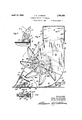
- This invention relates to a snow plow, and
- Fig. 2 is-a view in side elevation thereof
- - Fig. 3 1s a partial view in front elevation of the plow'as seen from the left of Fi .2;
- Fig. 4 is a plan view of a portion 0 the plow;
- v i Fig. 5 is a vertical section taken substantlally onhne 55 of Fig. 1, as indicated'by the arrows a elevating mechanism for the front of the j p
- Fig. 6 is a view partly in plan and partly in horizontal section of the central portion ofFig. 1, shown on an enlarged scale; and
- Fig.' 7 is a vertical section taken substantially on line 7-7 of Fig. 1.
- Fig. 9 is a Vertical section taken on the l1ne'9-9 of Fig. 4, as indicated by the arrow.
- the plow comprises a prow portion 10 and in the embodi- Inent' of the invention illustrated, this prow portion is formed by a pair of plates having rectilinear edges 10* bent into vertical planes and secured by aplurality of rivets 10 said edges extending. upwardlyandrearwardlyin i an inclined direction.
- Said plates which are designated as 10 and 10, form mold boards which extend rearwardly and laterally from the said front edges 10* and are curved into partial cylindrical or conical form and have their outer edges 10 and 10 respectively -substantially semicircular in shape and disposed invertical planes. As shown in Figs.
- edges 10 extend in a-straight line from-the lower'front portion of the plow to tendapproirimately throughout a half circle or sllghtly more than a half circle.
- a semicyllndrlcal plate 11 has one edge alined with the outer edges of each of the edges 10 and .boards which are closed by the plates 12 at the top thereof, and the edges l'O 'and 10 exi their outer. sides.
- the plate 12 extends up- .wardly above-the plates 11- with vertical front and rear edges and forms the outer 1 and segmental shaped 'side .havinga sma side of a rectangular chute 13-disposed directly over said plates 11 and said semi-cylindrical chambers, the inner side of which is formed by the plate 12" and the front and rear sides by the plates 12 and 12 respectively.
- Triangular brackets 14 are secured at each end of the chute 13 to the plates 12 and 12 respectively and snow deflecting members 15 are pivoted to the upper ends of said brackets 14 on the pivots 16 having a common horizontal axis.
- the members 15 have curved semi-cylindrical top portions rtions and their ends are adapted to over ap the sides of the chute 13 as shown in Fig. 3.
- the mold board plates 10 and 10 have extending therethrough and supported therein casings 17 having end closing members 18 forming bearings for shafts 19.
- a sleeve extends betweenand is journaled in the Gas- 17 and is splined to receive the inner en of the shafts 19 which are provided with a plurality of keys fitting in the splines in said sleeve.
- the sleeve 20 has a gear 21 secured thereto b which it is driven, the sleeve thus dri e shafts 19.
- a casing 22 is secured to e rear side of the casings 17 and forms the bearin for a shaft 23 having its rear end 'ro'vide with a plurality of keys, which en is adapted to be connected by'suitable coupling and universal joint tothemotor shaft of the propelling-automobile.
- the shaft 23 has a pinion 24 secured to its end and in the casin 17' meshing with r 21and adapted to rive'the same.
- -The afts 19 at their outer ends have secured thereto rotary snow propellin members 26.
- each member is shown as comprising a hub'casting 27 having circular flanges 27' ateach end and provided with suitable anti-friction bearings 28 adjacent each end forming the bearings for a sleevebearing 29 which encloses the shaft 19.
- a driving member 30 is secured to one end of the hub 27 having an angular socket or opening at its center in which an angular portion 19 of shaft 19 is adapted to fit, the shaft 19 having a cylindrical portion 19" beyond the portion 19 slidable in a cylindrical bore m a cap member 31 secured to the outer side of the member 30, which member 31 has a cylindrical exterior surface fitting in and runin'a 32 secured to the inner side of tile plate 12.
- Member 31 also has a small cylindrical projection at its outer end extending throu h anaperture in late 12 and lfoollar 33 pinned t ereto.
- shafts 19 each have secured thereto in the casing 17 clutch collars 84 and a pair of clutch levers 35. are pivoted in on the membore 17 and extend throu openin s in the members 17 having forke inner en engaging the collars 84.
- the levers 35 have operating handles projecting rearwardly.
- the hub 27 has secured to the flange at its outer end a s ider member 36 having an outer circular ange 36.
- a seriesv of plates 26 are secured to the flange 36 and to the flange 27 at the inner side of the hub member 27.
- the plates 26 are bent to be of trough shape as shown in Fig. 2 with their greatest width adjacent the flange 36, the said plates tapermg in width toward their outer ends so as to be substantially scoop-shaped.
- the plates 26 At their outer sides the plates 26 have end portions or lugs 26 extending to the outer side of the flange 36" bolted or riveted thereto and at their inner sides the plates have end portions or lugs 26 extending inwardly to and bolted or riveted to the inner flange 27" as shown in Fig. 2.
- a bracket 37 is provided having an arcuate flange 37 fitting theinner side of the flange 36 and secured thereto by the same bolts securin the lug 26".
- the bracket ex tends inwardly around the rear of the blade or plate 26 and has a lug 37 at its inner end by which it is also secured to said plate.
- the plates 26 are thus effectively braced by the brackets 37.
- the plates 10 and 10 are supported upon and secured at their lower edges to a shoe 38 having a shoulder formed thereon against which the edges of said plate abut, member 38 exteudin laterally and rearwardly with the edges 0 the plates 10 and 10 and ex- "tending under the plates 11, the rear end of member 38 being formed with apertured lugs 38' to whichthe push members 39 are secured.
- the members 39 will be attached at their other ends in some suitable manner to an automobile truck or tractor adapted to push the plow;
- the members 38 have secured thereto and extending-therebetween a heavy angle bar 40.
- Each of the plates 10 and 10- has secured to its rear. side a frame 41 comprising a curved angle bar' 41 riveted to said plates.
- the frame 41 which issubstantially triangular, has a lower rearwardly extending arm 41 having a recess in its outer end in which is disposed a nut block or member 42.
- the frame 41 has pivoted to its upper end a rearwardly extending bar 43 also aving an apertured lug 43' at its rear end.
- the bar 43 also has a vertically extendin hub 43" bored to receive the upper end 0 screw shaft 44 extending therethrough and downwardly into the nut 42.
- the shaft 44 has a collar 45 pinned intermediate its ends, between which and washer 46 engaging the lower side of the hub 43 is disposed a compression coil sprin 47.
- the frames 41. are connected by cross ars 47 as shown in Fig. 1.
- the member 38 has at its front portion in the rear of the plates 10 and 10 a pair of upwardly extending lugs 38 between which is pivoted the front end of a lever 47 extending rearwardly and u wardly and having its upper rear end em raced by a nut member 48*' through which passesa screw 49,
- a shoe comprising a plate '51 is provided, which has its front and rear ends curved upwardly and has a post 52 pivotedin lugsjadjacent its central portion the v upper end of which post is embraced by the lever 47 intermediate the ends thereof.
- plate 51- has .journaled therein a plurality of rollers 53 carried on shafts '54 journaled in lugs on said plate, said rollers extendin .through openings in said plate, and adapte to engage the ground or supporting surface for the plow.
- the plow will be propelled by atractor Or other means having members connected to the lugs 38 and 43.
- the shaft 23 as stated will be driven from the motorof the automobile and the shaft 19 will thus bedriven and will drive the propelling means upwardly at the rear of the plates 11 and into -.the chute 13.
- the snow is simply discharged at each side of the roadway. It is sometimes desired-to load the snow and remove the snow, as when the snow is cleared from city streets. It has also been found in practice that if a strong wind is blowing across'the road, it isdiflicult to discharge the snow laterally to one side of the road with the plow shown in applicants prior patent.
- the members 15 are thus provided, which'will direct the'snow in difierent'directions. When the member '15 is-disposed as shown in full linesin Fig. 3, the snow will be, deflected to the outer side or the same side,
- the member 15 can be disposed as shown in the dotted lines and thesnow will thus be elfectively delivered at the opposite side of the road and the opposite side of the plow from that on which the member 15. is mounted. At this time the member 15 on the other chute 15 will be turned in the same direction.
- the members 15 can 'alsobe used when it is desired to load the snow and will direct the snow to' one side in a comparatively narrow stream so that a wagon or truckcan practice and'found to As theplow is propelled along there is considerable vibration of the front end as the plow moves over the inequalities in the road surface, and some of the shock of this vibration will be'absorbed by the sprinv 47.
- The'shaft 44 can be turnedby the application of a wrench to its'upper end 'to bring the lug 43'and arm 41 closer together or farther apart. As the lug 43 will'be fixed by attachment to the tractor, this action willdrive alongside of the plow and receive the tend to respectively raise or lower the member 41 -and frame 41 to elevate or lower.
- lugs 43 extend to, the tractor frame, 1
- the front end of the plow can be elevated as desired by turning of the screw 49 by a suitable wrench.
- either shaft. 19 j can be connected or disconnected from its propeller 26.
- the plow can thus be quickly changed to operate with one or can be thrown out of action if desired.
- prow portion having a central rearwardly inclined edge extending upwardly at an angle of less than 45 degrees to the vertical, a'curved mold-board extending laterally and rearwardly at each side of said edge, a semi-cylindrical casing at the outer end of each mold board and substantially continuous therewith, having its outer side closed, a conduit extending upwardly from each of said casings having an open upper end, rotary snow propelling means adjacent -the outer end of each mold board and disposed in said casing for receivin the snow from'said mold board and proplling the same'upwardly in said conduits and pivoted swinging means at the top of each conduit for directing the snow in opposite directions.
- A'snow plow having in combination, a front prow portion having a central upwardly and rearwardlyinclined rectilinear edge, a curved mold board extending laterally and rearwardly from each side of said edge and terminating in a semi-cylindrical edge disposed in a vertical plane parallel to the longitudinal center line of said plow, a semicylindrical casing at the outer end of each mold board extending continuous therewith, a vertical plate at the outer side of each of said casings, shafts.
- rotary means comprising substantially radial extending trough-shaped snow propellers carried by each shaft and disosed adjacent the outer end of said mold oardsand in said casings, ing vertically from each of said casings open at their upper ends and adjustable swinging deflecting plates at the top of said conduits 'for-directing-the snow to either side of said plow.
- a snow plow having in combination, a front prow portion, a laterally and rearwardly extending mold board at each side of sa d portion, end walls at theouter sides of said plow, conduits extending upwardly above said propelling means and hav ng open upper ends, rotary snow propelling means ad acent the outer end of each mold board for receiving snow therefrom and directing the same upwardly in said conduits, and swinging segmental trough-shaped members pivoted inter-" mediate their ends above said conduits adjustable to direct the snow to either side of said plow.
- a snow plow having in combination, a mold board extending laterally and rearwardl at each side thereof, a rotary snow prope ler rotatable. about a horizontal axis and held from lateral movement adjacent the ⁇ outer end of eachof the mold boards, a driving shaft for each of said propellers adapted to be connected and disconnected to its respective propeller by a longitudinal sliding movement, means for moving each shaft lon gitudinally, a gear connected to said shafts for driving the same, a pinion meshing with said gear and a shaft for drivingsaid pinion projecting at the rear of the plow and adaptconduits extended to be connected to the motor shaft of an automobile.
- each of said propellers having a central hub, an angular socket in said hub, an angular portion on each of said shafts adapted to move into and out of engagement with said angular socket to connect or disconnect said shaft and propeller.
- a snow plow having in combination, laterally andrearwardly extending moldboards moving the rear end of said-link toward and from the rear end of said arm when-said link is connected to said pusher member and held from vertical movement thereby to raise and lower the rear end of said plow.
- a snow plow having in combination, laterally and .rearwardly extending mold boards diverging from a central front edge, means at'the rear of each mold board and adacent their outer ends and bottom edges adapted to be connected to a pusher member,
- a snow plow having in combination, a front prow portion and mold boards extendlnglaterally and rearw-ardly therefrom, a shoe having a ground engaging means disposed in the rear of said prow, a lever pivoted at one end to said prow, extendin rearwardly, a support for said lever on said shoe,
- a prow portion having a central upwardly and rearwardly'inclined edge, a curved mold board extending laterally and rearwardly at the side of said edge, a semi-cylindrical cas ing at the outer end of each mold board and support and constituting I l rotary member disposed moved by continuous therewith having its outer side closed, a conduit extending from said casing having an open outer end, rotary snow propelling means adjacent the outer end of said mold board and disposed in said casing for receiving the snow from said mold board, and propelling it through said conduit and means at the outer end of said conduit for directing said snow laterally.
- a snow plow having in combination a rotatable snow propelling means, comprising a plurality of members trougl1-shaped in cross section, said members extending radially and tapering in depth toward their outer ends, an annular member at one side of said members to which they are respectively connected, and means at the other side of said members to which they are connected at said latter side.
- a snow plow having in combination, a laterally extending mould board, a substantially semi-cylindrical chamber at theouter end of said mould board to which the snow is said mould board, said chamber having its outer end closed, a conduit extending upward from the top of said chamber, a in said chamber with its axis substantially coincident. with that of said chamber, said member having curved blades adapted to engagev the snow at the front and direct it upwardly substantially tangentially into said conduit.
- a snow plow having in combination, a laterally extending mould board, a substantially semi-cylindrical chamber at theouter end of said mould board to which the snow is moved by said mould board, said chamber having its outer end closed, a conduit extendi-ng upward from the top of said chamber,
- arotarymember disposedin said chamber with its axis substantially coincident with that of said chamber, said member having substantially lateral trough shaped blades, said blades having advanced edges at one side adapted to engage the snow at the front of said member and directthe same upwardly into said conduit.
- a snow plow having in combination laterally and rearwardly extending mold boards meeting in a central front edge, a frame rigidly mold board at an intermediate point thereon, said frame having an arm rigid therewith projecting rearwardly from its lower portion, an arm pivoted to the upper portion of said frame and extending rearwardly therefrom adapted to be connected to a pusher member, and means extending between said arms for relatively moving the same.
- a snow plow having in combination, a
- each front prow portion having a central upwardly and rearwardly inclined rectilinear edge, a curved mold board extending laterally and rearwardly from each side of said edge, a semi-cylindrical casing at the outer end of each mold board extending continuous therewith, a vertical plate at the outer side of each of said casings, shafts extending transversely of said mold boards and casings and concentric therewith, rotary snow propelling means carried by each shaft and disposed in said casings and conduits 7 extending vertically from each of said casings open at their upper ends through which show is discharged by said propelling means.
Landscapes
- Engineering & Computer Science (AREA)
- Architecture (AREA)
- Civil Engineering (AREA)
- Structural Engineering (AREA)
- Cleaning Of Streets, Tracks, Or Beaches (AREA)
Description
P 1930. J. o. JOHNSON 1,754,322
SNOWPLOW WITH TOP DISCHARGE Filed July 6, 1926 3 Sheets-Sheet 1 I N VE/V T017. JOHN 0. cTOHIYJfl/I.
April15, 1930. "J. o. JOHNSON 1,754,322
SN OWPLOW WITH 'IOP DISCHARGE Filed July 6, 1926 5 Sheets-Sheet 2 April 1930. .1. o. JOHNSON 1,754,322
SNOWPLOW WITH TOP DISCHARGE Filed July 6, 1926 5 Shee'ts-Sheet 3 Patented Apr. 15, 1930 I -UNrr-Eo STATES Jor'm o. .ronnson, or Mmnmroms, MINNESOTA, assmnon; BY mEsNE ASSIGN- MENTS, 'ro ENTERPRISE HOLDING COMPANY, or MINNEAPOLIS, MmNEso'rA, A
CORPORATION OF MINNESOTA snowrnow wrrn 'ror DISCHARGE,
. Application filed July 6,1926. Serial No. 120,603.
- This invention relates to a snow plow, and
- particularly to a snow plow adaptedtoclear highways.
It is an. object of this invention to provlde .asnow plow having a front centralprow portion and laterally and rearwardly extending mold boards leading to semi-cylindrical chambers in which are disposed rotating means adapted to receive and propel the snow upwardly through conduitsleadlng up-' ward from said chambers. i
It is afurther object of the invention to provide a snow plow such as set forth in-the preceding paragraph, together withmeans at the top .of-said conduits adapted to direct the snow'propelled therefrom in dlfierent directions, as to either'side of'the roadway Itis another object of the invention to provide a simple and efficient structure of rotary snow propelling means;
It is still another object of the invention to provide a snow .plow having mold boards and rotary snow propelling means adjacent thereto, together with adriving means for said propelling means adapted to be connected to and driven from the motor shaft ofan autom obile,\said plow being, provided with driving shafts for said propelling means and controlling devices by means of which said driving shafts may be connected or disconnected to said propelling means to throwthe same into or out of operation.
It is still a further object of the invention to provide a frame for said plowadapted to .be'connectd to pushing embers for mov-' ing the plow and arranged to tilt'the plow and to absorb some of the vibration thereof. It is still another object of the invention to provide a simple and eiiicient means for adjustingthe front portion of the plow.
These and other objects and advantages of the invention will be fully setforth in the following description made inxconnection with the accompanying drawings, in'which like reference characters refer to. similar parts throughout the several views and in which:- A q Fig. 1 i'sa stop plan View 'ofthe plow;
Fig. 2 is-a view in side elevation thereof,
some parts being broken away and othersshown in vertical section;
- Fig. 3 1s a partial view in front elevation of the plow'as seen from the left of Fi .2;
Fig. 4 isa plan view of a portion 0 the plow; v i Fig. 5 is a vertical section taken substantlally onhne 55 of Fig. 1, as indicated'by the arrows a elevating mechanism for the front of the j p Fig. 6 is a view partly in plan and partly in horizontal section of the central portion ofFig. 1, shown on an enlarged scale; and
Fig.' 7 is a vertical section taken substantially on line 7-7 of Fig. 1.
Fig. 8 is a horizontal section taken on line =8'8 of Fig. 2, as indicated'by the arrow;
and Fig. 9 is a Vertical section taken on the l1ne'9-9 of Fig. 4, as indicated by the arrow.
Referring to the drawings, the plow comprises a prow portion 10 and in the embodi- Inent' of the invention illustrated, this prow portion is formed by a pair of plates having rectilinear edges 10* bent into vertical planes and secured by aplurality of rivets 10 said edges extending. upwardlyandrearwardlyin i an inclined direction. Said plates, which are designated as 10 and 10, form mold boards which extend rearwardly and laterally from the said front edges 10* and are curved into partial cylindrical or conical form and have their outer edges 10 and 10 respectively -substantially semicircular in shape and disposed invertical planes. As shown in Figs. 2 and 7, the edges 10 extend in a-straight line from-the lower'front portion of the plow to tendapproirimately throughout a half circle or sllghtly more than a half circle. A semicyllndrlcal plate 11 has one edge alined with the outer edges of each of the edges 10 and .boards which are closed by the plates 12 at the top thereof, and the edges l'O 'and 10 exi their outer. sides. The plate 12 extends up- .wardly above-the plates 11- with vertical front and rear edges and forms the outer 1 and segmental shaped 'side .havinga sma side of a rectangular chute 13-disposed directly over said plates 11 and said semi-cylindrical chambers, the inner side of which is formed by the plate 12" and the front and rear sides by the plates 12 and 12 respectively. .Triangular brackets 14 are secured at each end of the chute 13 to the plates 12 and 12 respectively and snow deflecting members 15 are pivoted to the upper ends of said brackets 14 on the pivots 16 having a common horizontal axis. The members 15 have curved semi-cylindrical top portions rtions and their ends are adapted to over ap the sides of the chute 13 as shown in Fig. 3.
' The mold board plates 10 and 10 have extending therethrough and supported therein casings 17 having end closing members 18 forming bearings for shafts 19. A sleeve extends betweenand is journaled in the Gas- 17 and is splined to receive the inner en of the shafts 19 which are provided with a plurality of keys fitting in the splines in said sleeve. The sleeve 20 has a gear 21 secured thereto b which it is driven, the sleeve thus dri e shafts 19. A casing 22 is secured to e rear side of the casings 17 and forms the bearin for a shaft 23 having its rear end 'ro'vide with a plurality of keys, which en is adapted to be connected by'suitable coupling and universal joint tothemotor shaft of the propelling-automobile. The shaft 23 has a pinion 24 secured to its end and in the casin 17' meshing with r 21and adapted to rive'the same. -The afts 19 at their outer ends have secured thereto rotary snow propellin members 26. While these members may variouslyconstructed, in the embodiment of the invention illustrated, each member is shown as comprising a hub'casting 27 having circular flanges 27' ateach end and provided with suitable anti-friction bearings 28 adjacent each end forming the bearings for a sleevebearing 29 which encloses the shaft 19. A driving member 30 is secured to one end of the hub 27 having an angular socket or opening at its center in which an angular portion 19 of shaft 19 is adapted to fit, the shaft 19 having a cylindrical portion 19" beyond the portion 19 slidable in a cylindrical bore m a cap member 31 secured to the outer side of the member 30, which member 31 has a cylindrical exterior surface fitting in and runin'a 32 secured to the inner side of tile plate 12. Member 31 also has a small cylindrical projection at its outer end extending throu h anaperture in late 12 and lfoollar 33 pinned t ereto. The
shafts 19 each have secured thereto in the casing 17 clutch collars 84 and a pair of clutch levers 35. are pivoted in on the membore 17 and extend throu openin s in the members 17 having forke inner en engaging the collars 84. The levers 35 have operating handles projecting rearwardly. The hub 27 has secured to the flange at its outer end a s ider member 36 having an outer circular ange 36. A seriesv of plates 26 are secured to the flange 36 and to the flange 27 at the inner side of the hub member 27. The plates 26 are bent to be of trough shape as shown in Fig. 2 with their greatest width adjacent the flange 36, the said plates tapermg in width toward their outer ends so as to be substantially scoop-shaped. At their outer sides the plates 26 have end portions or lugs 26 extending to the outer side of the flange 36" bolted or riveted thereto and at their inner sides the plates have end portions or lugs 26 extending inwardly to and bolted or riveted to the inner flange 27" as shown in Fig. 2. A bracket 37 is provided having an arcuate flange 37 fitting theinner side of the flange 36 and secured thereto by the same bolts securin the lug 26". The bracket ex tends inwardly around the rear of the blade or plate 26 and has a lug 37 at its inner end by which it is also secured to said plate. The plates 26 are thus effectively braced by the brackets 37.
The plates 10 and 10 are supported upon and secured at their lower edges to a shoe 38 having a shoulder formed thereon against which the edges of said plate abut, member 38 exteudin laterally and rearwardly with the edges 0 the plates 10 and 10 and ex- "tending under the plates 11, the rear end of member 38 being formed with apertured lugs 38' to whichthe push members 39 are secured. The members 39 will be attached at their other ends in some suitable manner to an automobile truck or tractor adapted to push the plow; The members 38 have secured thereto and extending-therebetween a heavy angle bar 40. Each of the plates 10 and 10- has secured to its rear. side a frame 41 comprising a curved angle bar' 41 riveted to said plates. The frame 41 which issubstantially triangular, has a lower rearwardly extending arm 41 having a recess in its outer end in which is disposed a nut block or member 42. The frame 41 has pivoted to its upper end a rearwardly extending bar 43 also aving an apertured lug 43' at its rear end.
The bar 43 also has a vertically extendin hub 43" bored to receive the upper end 0 screw shaft 44 extending therethrough and downwardly into the nut 42. The shaft 44 has a collar 45 pinned intermediate its ends, between which and washer 46 engaging the lower side of the hub 43 is disposed a compression coil sprin 47. The frames 41.are connected by cross ars 47 as shown in Fig. 1. The member 38 has at its front portion in the rear of the plates 10 and 10 a pair of upwardly extending lugs 38 between which is pivoted the front end of a lever 47 extending rearwardly and u wardly and having its upper rear end em raced by a nut member 48*' through which passesa screw 49,
which screw passes through lever 47 and.
extends upwardly through a bearing member 50 secured to the rear of plates and 10, sald screw 49 having a squared upper end projetting through annaperture 10 1n the front --of the plow, adapted to receive a suitable socket Wrench. A shoe comprising a plate '51 is provided, which has its front and rear ends curved upwardly and has a post 52 pivotedin lugsjadjacent its central portion the v upper end of which post is embraced by the lever 47 intermediate the ends thereof. The
, plate 51- has .journaled therein a plurality of rollers 53 carried on shafts '54 journaled in lugs on said plate, said rollers extendin .through openings in said plate, and adapte to engage the ground or supporting surface for the plow.
In operation, the plow will be propelled by atractor Or other means having members connected to the lugs 38 and 43. The shaft 23 as stated will be driven from the motorof the automobile and the shaft 19 will thus bedriven and will drive the propelling means upwardly at the rear of the plates 11 and into -.the chute 13. -With the plow disclosed in applicants prior Patent, 1,524,518, the snow is simply discharged at each side of the roadway. It is sometimes desired-to load the snow and remove the snow, as when the snow is cleared from city streets. It has also been found in practice that if a strong wind is blowing across'the road, it isdiflicult to discharge the snow laterally to one side of the road with the plow shown in applicants prior patent. The members 15 are thus provided, which'will direct the'snow in difierent'directions. When the member '15 is-disposed as shown in full linesin Fig. 3, the snow will be, deflected to the outer side or the same side,
of the plow on which 'member 15 is disposed. If the member 15 is disposed as shown in .dotted lines in Fig. 3, the
snow will be directed across the top- 'of the plow to the other side of the road. If a wind be blowing across the road, therefore, and across the plow, the member 15 can be disposed as shown in the dotted lines and thesnow will thus be elfectively delivered at the opposite side of the road and the opposite side of the plow from that on which the member 15. is mounted. At this time the member 15 on the other chute 15 will be turned in the same direction. The members 15 can 'alsobe used when it is desired to load the snow and will direct the snow to' one side in a comparatively narrow stream so that a wagon or truckcan practice and'found to As theplow is propelled along there is considerable vibration of the front end as the plow moves over the inequalities in the road surface, and some of the shock of this vibration will be'absorbed by the sprinv 47. It will freely swing be noted that the link 43-cannot downwardly about its pivot, owing to the fact that the shaft 44 extends through the hub 43". The'shaft 44 can be turnedby the application of a wrench to its'upper end 'to bring the lug 43'and arm 41 closer together or farther apart. As the lug 43 will'be fixed by attachment to the tractor, this action willdrive alongside of the plow and receive the tend to respectively raise or lower the member 41 -and frame 41 to elevate or lower. the
rear end of the plow. The pusher bars 39.wi1l
be connected to a bar (not shown) extending transversely of the tractor, while the members connected to. lugs 43 extend to, the tractor frame, 1
It is sometimes-desired to leave some snow on the road and the front end of the plow can be elevated as desired by turning of the screw 49 by a suitable wrench. The front end of.
By shifting the" levers 35, either shaft. 19 j can be connected or disconnected from its propeller 26. When the shafts 19'are moved end- I wise so that the angular portion 19 moves out of registry with the member 30, the propeller will not be driven. The plow can thus be quickly changed to operate with one or can be thrown out of action if desired.
From the above description it is seen that applicant has provided a simple and efiici'ent snow plow and one which will quickly remove the snow and effectively dispose of the both of the propellers 26 and both propellers samel The plow is constructed of comparatively' few parts and these can be simply and ruggedly madeso that theplow will endure the heavy duty to which it is subjected. The device has been amply. demonstrated in actual be Very successful and etficient.
It will, of course,be understood that various changes may be made in the form, details, arrangement and proportions of 'the parts,
without departing" from the scope of apph- '120 sists in a device ca able of carrying out the cants invention, which, generally stated, conobjects above set orth, in the novel parts and combinations of parts disclosed and de-' fined in the appended claims; What 'is claimed is 1. A snow plow having in combination, a
prow portion having a central rearwardly inclined edge extending upwardly at an angle of less than 45 degrees to the vertical, a'curved mold-board extending laterally and rearwardly at each side of said edge, a semi-cylindrical casing at the outer end of each mold board and substantially continuous therewith, having its outer side closed, a conduit extending upwardly from each of said casings having an open upper end, rotary snow propelling means adjacent -the outer end of each mold board and disposed in said casing for receivin the snow from'said mold board and proplling the same'upwardly in said conduits and pivoted swinging means at the top of each conduit for directing the snow in opposite directions.
2. A'snow plow having in combination, a front prow portion having a central upwardly and rearwardlyinclined rectilinear edge, a curved mold board extending laterally and rearwardly from each side of said edge and terminating in a semi-cylindrical edge disposed in a vertical plane parallel to the longitudinal center line of said plow, a semicylindrical casing at the outer end of each mold board extending continuous therewith, a vertical plate at the outer side of each of said casings, shafts. extending transversely of said mold boards and casings, and concenv tric therewith, rotary means comprising substantially radial extending trough-shaped snow propellers carried by each shaft and disosed adjacent the outer end of said mold oardsand in said casings, ing vertically from each of said casings open at their upper ends and adjustable swinging deflecting plates at the top of said conduits 'for-directing-the snow to either side of said plow.
3. A snow plow having in combination, a front prow portion, a laterally and rearwardly extending mold board at each side of sa d portion, end walls at theouter sides of said plow, conduits extending upwardly above said propelling means and hav ng open upper ends, rotary snow propelling means ad acent the outer end of each mold board for receiving snow therefrom and directing the same upwardly in said conduits, and swinging segmental trough-shaped members pivoted inter-" mediate their ends above said conduits adjustable to direct the snow to either side of said plow. t
4. A snow plow having in combination, a mold board extending laterally and rearwardl at each side thereof, a rotary snow prope ler rotatable. about a horizontal axis and held from lateral movement adjacent the{ outer end of eachof the mold boards, a driving shaft for each of said propellers adapted to be connected and disconnected to its respective propeller by a longitudinal sliding movement, means for moving each shaft lon gitudinally, a gear connected to said shafts for driving the same, a pinion meshing with said gear and a shaft for drivingsaid pinion projecting at the rear of the plow and adaptconduits extended to be connected to the motor shaft of an automobile. I
5. The structure set forth in claim 4, each of said propellers having a central hub, an angular socket in said hub, an angular portion on each of said shafts adapted to move into and out of engagement with said angular socket to connect or disconnect said shaft and propeller.
6. A snow plow having in combination, laterally andrearwardly extending moldboards moving the rear end of said-link toward and from the rear end of said arm when-said link is connected to said pusher member and held from vertical movement thereby to raise and lower the rear end of said plow.
7, The structure setforth in claim 6, said last mentioned means com rising a screw shaft extending through a re in said link and engaging the nut held in the said arm.
' 8. A snow plow having in combination, laterally and .rearwardly extending mold boards diverging from a central front edge, means at'the rear of each mold board and adacent their outer ends and bottom edges adapted to be connected to a pusher member,
a frame secured to the rear of each mold board and having means extendin outwardly at the top thereof adapted to e secured to a pusher memberand resilient means between said last mentioned means and the bottom of said frame for absorbing the .vi-
bration of said plow as it moves over the road.
9. A snow plow having in combination, a front prow portion and mold boards extendlnglaterally and rearw-ardly therefrom, a shoe having a ground engaging means disposed in the rear of said prow, a lever pivoted at one end to said prow, extendin rearwardly, a support for said lever on said shoe,
and adjustable means connected to the other I end of said lever to move the same to raise and lower said prow portion.
10. The structure set forth in claim 9, and a roller revolubl carried by said shoe-at each side of sai said ground engagin means.
11. A snow plow aving in combination,
a prow portion having a central upwardly and rearwardly'inclined edge, a curved mold board extending laterally and rearwardly at the side of said edge, a semi-cylindrical cas ing at the outer end of each mold board and support and constituting I l rotary member disposed moved by continuous therewith having its outer side closed, a conduit extending from said casing having an open outer end, rotary snow propelling means adjacent the outer end of said mold board and disposed in said casing for receiving the snow from said mold board, and propelling it through said conduit and means at the outer end of said conduit for directing said snow laterally.
12. A snow plow having in combination a rotatable snow propelling means, comprising a plurality of members trougl1-shaped in cross section, said members extending radially and tapering in depth toward their outer ends, an annular member at one side of said members to which they are respectively connected, and means at the other side of said members to which they are connected at said latter side.
13. The structure set forth in claim 12, and a bracket disposed in the rear of each of said trough-shaped members shaped to embrace the same and secured thereto, said bracket being secured to said annular member.
14. A snow plow having in combination, a laterally extending mould board, a substantially semi-cylindrical chamber at theouter end of said mould board to which the snow is said mould board, said chamber having its outer end closed, a conduit extending upward from the top of said chamber, a in said chamber with its axis substantially coincident. with that of said chamber, said member having curved blades adapted to engagev the snow at the front and direct it upwardly substantially tangentially into said conduit.
15. A snow plow having in combination, a laterally extending mould board, a substantially semi-cylindrical chamber at theouter end of said mould board to which the snow is moved by said mould board, said chamber having its outer end closed, a conduit extendi-ng upward from the top of said chamber,
arotarymember disposedin said chamber with its axis substantially coincident with that of said chamber, said member having substantially lateral trough shaped blades, said blades having advanced edges at one side adapted to engage the snow at the front of said member and directthe same upwardly into said conduit.
16. A snow plow having in combination laterally and rearwardly extending mold boards meeting in a central front edge, a frame rigidly mold board at an intermediate point thereon, said frame having an arm rigid therewith projecting rearwardly from its lower portion, an arm pivoted to the upper portion of said frame and extending rearwardly therefrom adapted to be connected to a pusher member, and means extending between said arms for relatively moving the same.
17. A snow plow having in combination, a
secured to the rear side of each front prow portion having a central upwardly and rearwardly inclined rectilinear edge, a curved mold board extending laterally and rearwardly from each side of said edge, a semi-cylindrical casing at the outer end of each mold board extending continuous therewith, a vertical plate at the outer side of each of said casings, shafts extending transversely of said mold boards and casings and concentric therewith, rotary snow propelling means carried by each shaft and disposed in said casings and conduits 7 extending vertically from each of said casings open at their upper ends through which show is discharged by said propelling means.
In testimony whereof I affix my signature.
JOHN O. JOHNSON.
Priority Applications (1)
| Application Number | Priority Date | Filing Date | Title |
|---|---|---|---|
| US120603A US1754322A (en) | 1926-07-06 | 1926-07-06 | Snowplow with top discharge |
Applications Claiming Priority (1)
| Application Number | Priority Date | Filing Date | Title |
|---|---|---|---|
| US120603A US1754322A (en) | 1926-07-06 | 1926-07-06 | Snowplow with top discharge |
Publications (1)
| Publication Number | Publication Date |
|---|---|
| US1754322A true US1754322A (en) | 1930-04-15 |
Family
ID=22391381
Family Applications (1)
| Application Number | Title | Priority Date | Filing Date |
|---|---|---|---|
| US120603A Expired - Lifetime US1754322A (en) | 1926-07-06 | 1926-07-06 | Snowplow with top discharge |
Country Status (1)
| Country | Link |
|---|---|
| US (1) | US1754322A (en) |
Cited By (2)
| Publication number | Priority date | Publication date | Assignee | Title |
|---|---|---|---|---|
| US2778126A (en) * | 1953-06-08 | 1957-01-22 | Four Wheel Drive Auto Company | Plow apparatus for high speed snow removal without windrowing |
| US4391052A (en) * | 1981-12-23 | 1983-07-05 | Guy Jr Burlin A | Snow blower |
-
1926
- 1926-07-06 US US120603A patent/US1754322A/en not_active Expired - Lifetime
Cited By (2)
| Publication number | Priority date | Publication date | Assignee | Title |
|---|---|---|---|---|
| US2778126A (en) * | 1953-06-08 | 1957-01-22 | Four Wheel Drive Auto Company | Plow apparatus for high speed snow removal without windrowing |
| US4391052A (en) * | 1981-12-23 | 1983-07-05 | Guy Jr Burlin A | Snow blower |
Similar Documents
| Publication | Publication Date | Title |
|---|---|---|
| US3886675A (en) | Adjustable auger cover for snow blower | |
| JPH07122243B2 (en) | Improved snow blower auger and impeller | |
| CA1317318C (en) | Snow removal apparatus | |
| US1577561A (en) | Snowplow | |
| US4498253A (en) | Snow removal | |
| US1754322A (en) | Snowplow with top discharge | |
| US1638708A (en) | Snowplow | |
| US2770893A (en) | Rotary snow plow | |
| US1844706A (en) | Snowplow | |
| US1592304A (en) | Snow-removing apparatus | |
| US4367603A (en) | Snow caster having ring gear and spur gear drive means | |
| JP3460088B2 (en) | Snow thrower | |
| US2199723A (en) | Snowplow structure | |
| US2224869A (en) | Snowplow | |
| US4385457A (en) | Snow caster | |
| US1822827A (en) | Snow remover | |
| USRE26010E (en) | Rubin snow throwers | |
| US3299546A (en) | Rotary snow plow | |
| US2623308A (en) | Snow projector | |
| US1886069A (en) | Snow remover | |
| US3132429A (en) | Snow removing device | |
| US1563920A (en) | Snowplow | |
| USRE19754E (en) | Snowplow with side chutes | |
| US1334516A (en) | Street or road snowplow | |
| US2143699A (en) | Snow plow |