US1754319A - Lighter - Google Patents
Lighter Download PDFInfo
- Publication number
- US1754319A US1754319A US218168A US21816827A US1754319A US 1754319 A US1754319 A US 1754319A US 218168 A US218168 A US 218168A US 21816827 A US21816827 A US 21816827A US 1754319 A US1754319 A US 1754319A
- Authority
- US
- United States
- Prior art keywords
- wheel
- wick
- cover
- shield
- lighter
- Prior art date
- Legal status (The legal status is an assumption and is not a legal conclusion. Google has not performed a legal analysis and makes no representation as to the accuracy of the status listed.)
- Expired - Lifetime
Links
Images
Classifications
-
- F—MECHANICAL ENGINEERING; LIGHTING; HEATING; WEAPONS; BLASTING
- F23—COMBUSTION APPARATUS; COMBUSTION PROCESSES
- F23Q—IGNITION; EXTINGUISHING-DEVICES
- F23Q2/00—Lighters containing fuel, e.g. for cigarettes
- F23Q2/02—Lighters with liquid fuel fuel which is fluid at atmospheric pressure
- F23Q2/04—Lighters with liquid fuel fuel which is fluid at atmospheric pressure with cerium-iron alloy and wick with friction ignition
- F23Q2/06—Lighters with liquid fuel fuel which is fluid at atmospheric pressure with cerium-iron alloy and wick with friction ignition with friction wheel
- F23Q2/08—Lighters with liquid fuel fuel which is fluid at atmospheric pressure with cerium-iron alloy and wick with friction ignition with friction wheel with ignition by spring action of the cover
Definitions
- This invention relates to lighters of the Vtype wherein a toothed Wheel abrades a pyrophoric member and throws sparks on to a suitable wick for igniting the wick.
- the wheel has most frequently been operatedeither automatically by means of springs after the wheel oper ating mechanism has been manually released, or the wheel has been manually operated directly as bymeans of the thumb.
- the automatically operated lighters are open to the objection that the normally locked operating mechanism may be unintentionally or accidentally released, in the pocket, as by coming into contact with articles carried in the pocket or with the material o-f the pocket itself, with consequent danger of setting fire to the pocket.
- My invention is designed to provide a lighter in which the wick flame is protected, the wheel automatically operated only when the lock mechanism therefor is designedly released, and in which the other objections above set forth are met.
- Fig. 1 is a front view of my improved lighter, showing the parts in the locked positions thereof.
- Fig. 2 is a vertical section of the same, showing the parts in the positions assumed thereby after the wheel has been operated to strike a light.
- Fig. 3 is a top plan View of the lighter shown in Fig. 1. 1
- Fig. 4 is a bottom plan view of the same.
- Fig. 5 is a front view of a modified form of locking catch particularly adapted to prevent accidental release thereof
- I Fig. 6 is a vertical section of part of the lighter showing a modified form of the wheel operating mechanism, whereby the Wheel is rotated in one direction only.
- the casing. 10 is made of suitable size and shape to fit easily into the pocket of the user, and is designed to hold inflammable liquid 11 therein, such as benzine, alcohol or the like, or to hold absorbent material soaked with such liquid.
- the wick bushing 12, adapted to hold the wick 9, is removably maintained in place in theupper end 13 of the casing as by means of a threaded connection therewith, or a tight fit., or in any other suitable manner which will suggest itself to those skilled in the art.
- An extending flange 14 may be provided on the bushing 12 for forming' a leakproof joint with the casing as will be described more fully hereinafter.
- the difficulty heretofore experienced when trying to insert a wick into the holder is obviated. It has heretofore beencustomary to compress the wick downwardly into the holder therefor, pushing the entire length of the wick through the holder. With my improved construction, the wick holder may be removed entirely, after whichV only the upper end of the wick is pushed up through the opening in the holder until that end projects slightly through the holder. The depending portion of the wick need then only be iiiserted into the casing and the bushing replaced.
- Adjustment of the wick is effected before securing the parts together by pulling either on the projecting upper end or on the lower end, it being understood that the wick being of soft material is much more easily arranged in position by pulling thereon than by attempting-to force it through an opening by compression.
- Replacement of the wick by the user when it has been burnt out may also be effected rapidlyT and easily in the same manner ⁇ without the necessity for using special tools for that purpose.
- a flint cylinder 15 of the usual type is supported in the flint holding tube 16, which is inclined sufiiciently' to bring the upper end of the flint in the proper position relatively to the toothed spark producing Wheel 17 and to bring the lower end l8of the tube near the tube I6 and bearing on the flint 15 serves to maintain said flint at all times in ressed engagement with the sparking wheel 1
- the lower end ofthe tube 16 may be threaded to receive the spring adjusting screw 21, though it is obvious that said screw may be dispensed with if desired, and the lower end of the sprin allowed to rest directl against the head g2 of the screw plug 19, w ich normally conceals said screw and said s ring.
- the casing is replenished with li u1d by removing the plug 19 turning the lig ter u slde down, and pourin liqui in through t e openm therefor. ,l t w1ll be seen that removal o said plu also exposes the adjusting screw 21, so that t e pressure'on the flint may be adjusted at the same time, if desired.
- a leak roof 'oint between the casing and t e plug pre er to arrange a suitable washer as 23 between the head 22 of the plug and the bottom of the casing.
- Figs. 2 and 6 may engage the cover 25 while the other end may en age the shield 28, as shown, Figs. 2 and 6 though it will be understoo that the ends of the spring may be otherwise arranged, provided only that movement of the cover toward locked position winds u or stresses said spring, and movement o the cover toward the released position thereof (Fig. 2),allows the spring to unwind itself.
- the circumferential surface i ofthe wheel is inv close contact, with the inner faces of the cover 25, whereby the wheel teeth engage the cover and the wheel is prevented from moving relatively thereto.
- movement of the cover causes corresponding movement of the wheel.
- the wheel is mounted on the shaft 24 inde endently of the cover and may move inde en entl therewhich urges the ball toward the narrow part of the s ace 31 and into engagement with the wheesteeth.
- the ball When, however, the cover is rotatedy in a clockwise direction, .the ball tends to slip over the wheel teeth and to remain nearer the upper part of the space 31 and does not therefore operatively connect the cover and the wheel together, whereby movement of the cover does not effect movement of the wheel.
- the spring 32 is preferably used to insure the action above described thoughkit may be dis ensed with if the space 31 is properly shapedi It will be understood .that while I have shown one form of operative ball clutch, for the urpose mentioned, I do not wish to be limited to said form since any other suitable types of such clutch may Ibe used instead.
- the cam rod 35 which controls th'e movement of the wheel, is secured to and protects the cap 33, and is suitably curved and constricted at its free end to form the cam 36.
- the grooved post 37 Suitably fastened to the top 13 of the casing is the grooved post 37, in the groove 38 of which is pivoted the trigger catch 39 as on the shaft 40, said trigger being protected and substantially enclosed y said post.
- Said spring normally acts on the arm 43 of the trigger catch for urging said catch toward the locking position thereof, so that after the cam 36 has passed the hook end 4l, said end engages the flat upper side of the cam rod and maintains lsaid rod in the locked position thereof.
- a suitable lug as 44 may be provided on the trigger catch for preventing the spring 42 from rotating said catch too far.
- the arm 43 extends but slightly outside of the post 37 and does not present a projection long enough to be accidentally operated.
- the arm 43 mayv terminate in the slightly projectingv finger piece 45, which, when depressed, removes the hook end 4l from the cam rod and allows the coil spring 29 to rotate the rod together with the wick cap, the wheel coverand wheel, with a rapid movement, whereby the wheel strikes sparks from the flint and ignites the wick.
- the wick cap extinguishes the wick flame
- the spring 29 is put under stress or wound up ready to lift the rod 35 when it is again released, andthe rod is locked in place by th trigger catch.
- the arm 43 of the catch may be dispensed with to obviate all danger o said arm being accidentally or unintentionally operated, and the catch may instead be formed with a serrated curved surface 46 of substantial length designed to be i rotated by the thumb, and extending but slightly outside of the post 37. There'being no decided projections on this ⁇ form of catch, there is no danger whatever that it may accidentally be unlocked.
- wick shield 28 held to the casing top 13 by the wick bushing 12, or soldered or otherwise secured thereto as by suitable screws or rivets.
- opening 47 may be provided in one end of the shield to allow the passage of the rod 35, the other end of the shield being left open if desired, to receive the wheel cover 25 or that end may be partly closed, the top of the shield being open.
- window openings 48 are provided formed by pressing part of the material L19of the shield outwardly or inwardly as may be preferred, provided that the window material 49 is inclined 1n ⁇ such a manner as to direct the air entering the shield upwardly toward the top of the flame so that the flame canont be extinguished by the entering air.
- a suitable washer similar to the washer 23 may be interposed between the fiange 14 of the wick holder and the base of I the shield.
- a wind shield of less widt and length than the top ofthe container and secured thereto inwardly-of the periphery of the top said shield having an v open end adyacent one end of the top and being closed at the other end thereofand open at the top, and having perforations inthe sides thereof fortthe ⁇ passa-ge ofair, a shaft passing through the ⁇ shield near the open end thereof, an ⁇ abrading wheel loosely necting the cover member to said wheel for rotating said wheel on movement of said member out of its initial position, comprising an element movable with said member and forced thereby into operative engagement with the periphery of said wheel and movable with said member relatively to and about the periphery of the wheel on movement ofvsaid -member towards its initial position.
- a lighter In a lighter, a container, a wind-shield of less length than the top of the container mounted on said top, and openat one end and the top thereof and closed at the other end, the open end of the wind-shield being near and above one of the sides of the container, an abrading wheel pivoted to the wind-shield near said open end, a lever comprising a wheel cover mounted on the same axis as the wheel, a wick cap on one-side of said cover depending below the bottom edge of said cover, and an elongated member extending beyond said cap, and movable means arranged between the cover and theperiphery of the wheel for engaging said periphery on movement of the cover in one direction to rotate the wheel, and movable relatively to the wheel on movement of the cover in the opposite direction.
- a substantially cylindrical post having a substantially vertical groove therein, a spring-pressed swingable operating lever having a substantially iiat top at one end thereof, two Hat sides spaced apart a distance less than any other dimension of said lever and substantially perpendicular to said top, and having a curved end between said sides serving as a cam and meeting said top and said sides, said top, sides and curved end forming the free extremity of said lever and being adapted to enter the groove of said post and to be entirely concealed therein, ⁇ a springpressed disc pivoted to said post within said groove and having a hook end projecting beyond said groove on one side of said post and bounded by a roughened arcuate anti-fric# tion surface beyond said hook end concentric with the pivot of said member and arranged below the top of said post and projecting beyond the other side of said post a slight distance suiiicientjonly to enable the roughened surface to vbe manually engaged by a tion and being adapted to'move forwardly automatically to close over said flat
- a swingable member having one end ree and reduced in thickness and curved at its extreme end surface to serve as a cam
- a swingable pivoted latch provided with means for engaging the uppermost surface of the free end of said member, said latch having a pair of at parallel surfaces and an arcuate roughened anti-friction surface perpendicular to and joining the flat surfaces, and concentric with the pivot of the latch, and a spring urging said latch into locking position
- said latch being adapted to be movedmanually against the action of the spring by the engagement of the finger of the user with said roughened surface to release said member, and being moved by the direct engagement therewith of the curved cam end of the member against the action of said spring on the movement of said member into initial position, and being moved again by said spring into locking position with said means over the top and outside of the extremity of the free end of said member after said top has passed said means.
- a fuel container of substantially rectangular outline having a substantially fiat top and'bottom, a tube within said container, a block of pyrophoric material fyieldably supported in said tube, a pair o parallel spaced projections upstandmg from said top near one end thereof, a shaft passing through said projections, an abrading wheel mounted on said shaft between the projections, a wick projecting above said top adjacent said wheel, a cover member for the wheel pivotally mounted on said shaft and having depending sides arranged between said projections and said wheel and havin a top to cover the wheel, an extension on sai cover member of sufficient length to extend close to the other end of said top, a snuiling cap carried by said extension intermediate of the ends thereof to cover the wick, said extension being shaped at its extreme free end to permit the locking thereof in place, a post at said other end of said top, a spring-pressed element mounted in said post and being substantially enclosed thereby, said element being arranged to be engaged and moved in one direction by the extreme
- a fuel container having a substantiallyv flat top and bottom, a Wind shield including a pair of projections near one end of the top spaced apart a distance less than the Width of said top, and upstanding from said top inwardly of one end thereof, the remainder of said wind shield extending on one side of said projections toward the other end of the top, and having a closed end thereon, and spaced inwardly from the peri heral su stantially the height of said projections, a Wick projecting through said top intermediate the ends of said Wind shield, a horizontal shaft supported by said projections, a peripherally toothed abrading Wheel on the shaft between said projections, and means for operating said wheel in one direction only, for capping said wick, and for coveringy said wheel, comprising a wheel cover arranged about said wheel, and having depending sides pivoted on said shaft and arranged inside of said projections, a wick cap depending below said cover, and a member extending past said cap, and arranged normally at the top of the wind shield
- a fuel container having a flat top and ottom, a pair of spaced projections u standing from said top near one end thereo a post of at least the height of said projections above said top rigidly secured to said top at the other end thereof, a horizontal shaft carried b said projections, a toothed wheel on said s aft, a wick projecting above said top intermediate said wheel and said edge of said top throughout and of llO wheel and operatively connectable vthereto pivotally mounted on said shaft, said lever including at one extremity thereof an elongated member having a uniform cross-section throughout substantially its entire length, said member having a terminal portion of not greater cross-sectional area than that of the remainder of said member, said portion in its locked position extending to a point inwardly of the outermost face of the post, said lever including further a cap intermediate the extremities thereof depending below said member, said lever terminating at its other extremity in a covering member partly enclosing the wheel, and extending above
- a lighter having a flat top and bottom, a pair of projections upstanding from said top, a peripherally toothed abrading wheel revolvably mounted between said projections, a. wick projecting from the top adjacent to and atone side of the wheel, a
- pyrophoric element yieldingly supported against said wheel, a wheel operating member supported by the casing, and a bodily movable rolling element within the operating i substantially 'flat top, a tube within said conmember, operatively connecting the operating member to the wheel and engaging the toothed periphery of the wheel for rotating the wheel to light the wick when said operating member is moved in one direction and being moved relatively to the toothed periphery of said wheel when said operating member is moved in the opposite direction.
- a casing having a substantially flat top, a pair of spaced supporting members upstanding from the top, a peripherally toothed abrading wheel revolubly mounted between said members above the top of the casing, a wheel operating member mounted between said spaced members and outside of the wheel, and means for operatively connecting the operating member to the wheel, on movement of the operating member in one direction comprising a movable rolling element engaging the toothed periphery of the wheel and confined between the wheel and said operating member.
- a fuel container having a tainer, a block of pyrophoric material yieldably supported in said tube, a pair of parallei spaced projections upstanding from said top near one end thereof, a shaft passing through said projections, an abrading wheel mounted on said shaft between the projections, a wick projecting above said top adjacent said wheel, an operating member for the wheel pivot-ally mounted on said shaft and having depending sides arranged between said projections and said wheel, a snuiiing cap carried by said member intermediate of the ends thereof to cover the wick, said member being shaped at its eXtreme free end to permit the locking thereof in place, a post at the other end of said top, a spring-pressed element mounted in said post and being substantially enclosed thereby, said element being arranged to be engaged and moved in one direction by the extreme shaped end of said memberv when said member,l is swung on its pivot to cap the wick and extinguish the light, and to move automatically in the other direction for engaging and locking said extreme
Landscapes
- Engineering & Computer Science (AREA)
- Chemical & Material Sciences (AREA)
- Combustion & Propulsion (AREA)
- Mechanical Engineering (AREA)
- General Engineering & Computer Science (AREA)
- Lighters Containing Fuel (AREA)
Description
April 15, 1930. J. HoLTzMAN i 1,754,319
l LIGHTER Filed sel-1t. a, 1927 2s N wi? jef-1; 4g i Il 'i W (Wl i INVENTOR John Holzman ATTORNEY Patented Apr. 15, 1930 UNITED STATES JOHN noLfrzMAN, or NEwYonx, NuY.'
LIGHTER Application filed September 8, 1927. Serial No. 218,168.
This invention relates to lighters of the Vtype wherein a toothed Wheel abrades a pyrophoric member and throws sparks on to a suitable wick for igniting the wick. In those lighters which have been previously designed to ne carried in the pocket, the wheel has most frequently been operatedeither automatically by means of springs after the wheel oper ating mechanism has been manually released, or the wheel has been manually operated directly as bymeans of the thumb. The automatically operated lighters, however, are open to the objection that the normally locked operating mechanism may be unintentionally or accidentally released, in the pocket, as by coming into contact with articles carried in the pocket or with the material o-f the pocket itself, with consequent danger of setting fire to the pocket. Those lighters having a manually operated Wheel are objectionable for the reason that the thumb or linger used for turning the wheel is readily soiled thereby and sometimes abraded and injured. In both types of lighters, the wick flame is readily extinguished by a slight air movement, draft or breeze.
My invention is designed to provide a lighter in which the wick flame is protected, the wheel automatically operated only when the lock mechanism therefor is designedly released, and in which the other objections above set forth are met.
The various objects of my invention will be clear from the description which follows, and from the drawings, in which, f
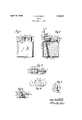
Fig. 1 is a front view of my improved lighter, showing the parts in the locked positions thereof.
Fig. 2 is a vertical section of the same, showing the parts in the positions assumed thereby after the wheel has been operated to strike a light.
Fig. 3 is a top plan View of the lighter shown in Fig. 1. 1
Fig. 4 is a bottom plan view of the same.
Fig. 5 is a front view of a modified form of locking catch particularly adapted to prevent accidental release thereof, and I Fig. 6 is a vertical section of part of the lighter showing a modified form of the wheel operating mechanism, whereby the Wheel is rotated in one direction only.
In that practical embodiment of my invention which I have illustrated herein, the casing. 10 is made of suitable size and shape to fit easily into the pocket of the user, and is designed to hold inflammable liquid 11 therein, such as benzine, alcohol or the like, or to hold absorbent material soaked with such liquid. The wick bushing 12, adapted to hold the wick 9, is removably maintained in place in theupper end 13 of the casing as by means of a threaded connection therewith, or a tight fit., or in any other suitable manner which will suggest itself to those skilled in the art. An extending flange 14 may be provided on the bushing 12 for forming' a leakproof joint with the casing as will be described more fully hereinafter. By making the wick holder removable, the difficulty heretofore experienced when trying to insert a wick into the holder is obviated. It has heretofore beencustomary to compress the wick downwardly into the holder therefor, pushing the entire length of the wick through the holder. With my improved construction, the wick holder may be removed entirely, after whichV only the upper end of the wick is pushed up through the opening in the holder until that end projects slightly through the holder. The depending portion of the wick need then only be iiiserted into the casing and the bushing replaced. Adjustment of the wick is effected before securing the parts together by pulling either on the projecting upper end or on the lower end, it being understood that the wick being of soft material is much more easily arranged in position by pulling thereon than by attempting-to force it through an opening by compression. Replacement of the wick by the user when it has been burnt out may also be effected rapidlyT and easily in the same manner `without the necessity for using special tools for that purpose.
A flint cylinder 15 of the usual typeis supported in the flint holding tube 16, which is inclined sufiiciently' to bring the upper end of the flint in the proper position relatively to the toothed spark producing Wheel 17 and to bring the lower end l8of the tube near the tube I6 and bearing on the flint 15 serves to maintain said flint at all times in ressed engagement with the sparking wheel 1 The lower end ofthe tube 16 may be threaded to receive the spring adjusting screw 21, though it is obvious that said screw may be dispensed with if desired, and the lower end of the sprin allowed to rest directl against the head g2 of the screw plug 19, w ich normally conceals said screw and said s ring. The casing is replenished with li u1d by removing the plug 19 turning the lig ter u slde down, and pourin liqui in through t e openm therefor. ,l t w1ll be seen that removal o said plu also exposes the adjusting screw 21, so that t e pressure'on the flint may be adjusted at the same time, if desired. For 1nsurin a leak roof 'oint between the casing and t e plug, pre er to arrange a suitable washer as 23 between the head 22 of the plug and the bottom of the casing.
The device for automatically operating the toothed spark roducin wheel 17 will now be described. aid whee is loosely or lixedly mounted as may be found preferable, on the shaft 24 and is 'ven its rotative movement through the me ium of the swinging wheel cover 25 which is also mounted on said shaft. The shaft 24 passes through the sides 26 of said cover and is su ported in the upstandin sides 27 of the wic shield 28. One end o the coil spring 29, mounted on the shaft 24,
may engage the cover 25 while the other end may en age the shield 28, as shown, Figs. 2 and 6 though it will be understoo that the ends of the spring may be otherwise arranged, provided only that movement of the cover toward locked position winds u or stresses said spring, and movement o the cover toward the released position thereof (Fig. 2),allows the spring to unwind itself.
In that form of the wheel mounting illustrated in Fig. 2, the circumferential surface i ofthe wheel is inv close contact, with the inner faces of the cover 25, whereby the wheel teeth engage the cover and the wheel is prevented from moving relatively thereto. In this construction, movement of the cover causes corresponding movement of the wheel. In the form illustrated in Fig. 6, however, the wheel is mounted on the shaft 24 inde endently of the cover and may move inde en entl therewhich urges the ball toward the narrow part of the s ace 31 and into engagement with the wheesteeth. When the cover is rotated in a counter clockwise direction, as viewed in the various figures, the ball is jammed between the wheel and the cover in the narrow part of the space 31 and causes both to rotate together. When, however, the cover is rotatedy in a clockwise direction, .the ball tends to slip over the wheel teeth and to remain nearer the upper part of the space 31 and does not therefore operatively connect the cover and the wheel together, whereby movement of the cover does not effect movement of the wheel. The spring 32 is preferably used to insure the action above described thoughkit may be dis ensed with if the space 31 is properly shapedi It will be understood .that while I have shown one form of operative ball clutch, for the urpose mentioned, I do not wish to be limite to said form since any other suitable types of such clutch may Ibe used instead.
the parts, the bottom edge of the cap, which rotates together with the cover 25, en ages the upper surface of the iiange 14 angl excludes air from the wick thereby extinguishing the wick Hame. The cam rod 35 which controls th'e movement of the wheel, is secured to and protects the cap 33, and is suitably curved and constricted at its free end to form the cam 36. Suitably fastened to the top 13 of the casing is the grooved post 37, in the groove 38 of which is pivoted the trigger catch 39 as on the shaft 40, said trigger being protected and substantially enclosed y said post. When the cam rod 35 is depressed, the cam 36 engages the hook end 41 of the trigger catch which extends slightly outside of the post, and forces said catch to rotate out of t e ay of the cam about the shaft`40 and agaiii/vst the action of the compression spring 42.
Said spring normally acts on the arm 43 of the trigger catch for urging said catch toward the locking position thereof, so that after the cam 36 has passed the hook end 4l, said end engages the flat upper side of the cam rod and maintains lsaid rod in the locked position thereof. A suitable lug as 44 may be provided on the trigger catch for preventing the spring 42 from rotating said catch too far. The arm 43 extends but slightly outside of the post 37 and does not present a projection long enough to be accidentally operated. If desired, the arm 43 mayv terminate in the slightly projectingv finger piece 45, which, when depressed, removes the hook end 4l from the cam rod and allows the coil spring 29 to rotate the rod together with the wick cap, the wheel coverand wheel, with a rapid movement, whereby the wheel strikes sparks from the flint and ignites the wick. When the rod and the parts connected thereto are rotated in the opposite direction, the wick cap extinguishes the wick flame, the spring 29 is put under stress or wound up ready to lift the rod 35 when it is again released, andthe rod is locked in place by th trigger catch. f
As indicated in Fig.v 5, the arm 43 of the catch ma be dispensed with to obviate all danger o said arm being accidentally or unintentionally operated, and the catch may instead be formed with a serrated curved surface 46 of substantial length designed to be i rotated by the thumb, and extending but slightly outside of the post 37. There'being no decided projections on this `form of catch, there is no danger whatever that it may accidentally be unlocked.
In order to enable the user to use the lighter in a breeze, I provide the wick shield 28, held to the casing top 13 by the wick bushing 12, or soldered or otherwise secured thereto as by suitable screws or rivets. An
, opening 47 may be provided in one end of the shield to allow the passage of the rod 35, the other end of the shield being left open if desired, to receive the wheel cover 25 or that end may be partly closed, the top of the shield being open. For supplying air to the wick,
- window openings 48 are provided formed by pressing part of the material L19of the shield outwardly or inwardly as may be preferred, provided that the window material 49 is inclined 1n `such a manner as to direct the air entering the shield upwardly toward the top of the flame so that the flame canont be extinguished by the entering air. To prevent leakage of liquid into the shield and about the wick holder, a suitable washer similar to the washer 23 may be interposed between the fiange 14 of the wick holder and the base of I the shield.
It will be seen that I have provided an improved lighter well adapted to operate under the severe conditions of practical use and for the .purposes for which it is intended. I do not intend to be understood, however, as limiting myself to the specific structures shown and described, since variousl changes in the illustrated embodiments of my invention may be made without departing from the-spirit and scope thereofor from the range of equivalents afforded by the appended claims.
I claim:
1. In a li hter, Va container, a wind shield of less widt and length than the top ofthe container and secured thereto inwardly-of the periphery of the top, said shield having an v open end adyacent one end of the top and being closed at the other end thereofand open at the top, and having perforations inthe sides thereof fortthe `passa-ge ofair, a shaft passing through the` shield near the open end thereof, an `abrading wheel loosely necting the cover member to said wheel for rotating said wheel on movement of said member out of its initial position, comprising an element movable with said member and forced thereby into operative engagement with the periphery of said wheel and movable with said member relatively to and about the periphery of the wheel on movement ofvsaid -member towards its initial position.
2. In a lighter, a container, a wind-shield of less length than the top of the container mounted on said top, and openat one end and the top thereof and closed at the other end, the open end of the wind-shield being near and above one of the sides of the container, an abrading wheel pivoted to the wind-shield near said open end, a lever comprising a wheel cover mounted on the same axis as the wheel, a wick cap on one-side of said cover depending below the bottom edge of said cover, and an elongated member extending beyond said cap, and movable means arranged between the cover and theperiphery of the wheel for engaging said periphery on movement of the cover in one direction to rotate the wheel, and movable relatively to the wheel on movement of the cover in the opposite direction.
3. In a lighter, a substantially cylindrical posthaving a substantially vertical groove therein, a spring-pressed swingable operating lever having a substantially iiat top at one end thereof, two Hat sides spaced apart a distance less than any other dimension of said lever and substantially perpendicular to said top, and having a curved end between said sides serving as a cam and meeting said top and said sides, said top, sides and curved end forming the free extremity of said lever and being adapted to enter the groove of said post and to be entirely concealed therein,`a springpressed disc pivoted to said post within said groove and having a hook end projecting beyond said groove on one side of said post and bounded by a roughened arcuate anti-fric# tion surface beyond said hook end concentric with the pivot of said member and arranged below the top of said post and projecting beyond the other side of said post a slight distance suiiicientjonly to enable the roughened surface to vbe manually engaged by a tion and being adapted to'move forwardly automatically to close over said flat top and to lock said lever in its initial position.
4. In a li hter, a swingable member having one end ree and reduced in thickness and curved at its extreme end surface to serve as a cam, a swingable pivoted latch provided with means for engaging the uppermost surface of the free end of said member, said latch having a pair of at parallel surfaces and an arcuate roughened anti-friction surface perpendicular to and joining the flat surfaces, and concentric with the pivot of the latch, and a spring urging said latch into locking position, said latch being adapted to be movedmanually against the action of the spring by the engagement of the finger of the user with said roughened surface to release said member, and being moved by the direct engagement therewith of the curved cam end of the member against the action of said spring on the movement of said member into initial position, and being moved again by said spring into locking position with said means over the top and outside of the extremity of the free end of said member after said top has passed said means.
5. In a lighter, com rising a fuel container of rectangu ar shape aving a substantially flat top and bottom walls, a tube passing within said container, a block of pyrophoric material yieldingly supported 1n said tube, a portion of sald tube being projected above the top Wall of the container, a windshield mounted on said top wall and secured thereto inwardly of the periphery of said top, said shield bein open adjacent one end of the top wall and c osed at the other end thereof, a wick projecting above said top and being substantially encircled by said shield, a shaft passing through the side walls of said shield near the open end thereof, an abrading wheel mounted on said shaft, a cover member pivotally mounted on said shaft having depending sides arranged inside of the shield and having a flat top to cover the wheel, a cylindrical wick cap secured t-o said member, spring means for resisting movement of the cover member out of its open position, said cover member being operatively connected to the wheel whereby to rotate the wheel to produce sparks to light the wick when actuated on its pivot in one direction, and to cap the wick and extinguish the light when actuated in the opposite direction against the action of said spring means.
6. In a lighter, a fuel container of substantially rectangular outline having a substantially fiat top and'bottom, a tube within said container, a block of pyrophoric material fyieldably supported in said tube, a pair o parallel spaced projections upstandmg from said top near one end thereof, a shaft passing through said projections, an abrading wheel mounted on said shaft between the projections, a wick projecting above said top adjacent said wheel, a cover member for the wheel pivotally mounted on said shaft and having depending sides arranged between said projections and said wheel and havin a top to cover the wheel, an extension on sai cover member of sufficient length to extend close to the other end of said top, a snuiling cap carried by said extension intermediate of the ends thereof to cover the wick, said extension being shaped at its extreme free end to permit the locking thereof in place, a post at said other end of said top, a spring-pressed element mounted in said post and being substantially enclosed thereby, said element being arranged to be engaged and moved in one direction by the extreme shaped end of said extension when said cover member is sWun on its pivot to cap the wick and extinguish tle light, and to move automatically in the other direction for engaging and locking said extreme shaped end of the extension.
7. In a lighter, a fuel container having a substantiallyv flat top and bottom, a Wind shield including a pair of projections near one end of the top spaced apart a distance less than the Width of said top, and upstanding from said top inwardly of one end thereof, the remainder of said wind shield extending on one side of said projections toward the other end of the top, and having a closed end thereon, and spaced inwardly from the peri heral su stantially the height of said projections, a Wick projecting through said top intermediate the ends of said Wind shield, a horizontal shaft supported by said projections, a peripherally toothed abrading Wheel on the shaft between said projections, and means for operating said wheel in one direction only, for capping said wick, and for coveringy said wheel, comprising a wheel cover arranged about said wheel, and having depending sides pivoted on said shaft and arranged inside of said projections, a wick cap depending below said cover, and a member extending past said cap, and arranged normally at the top of the wind shield, and an element movable with the wheel cover, forced against the toothed peripheral surface of the wheel on movement of the cover out of its initial position to rotate the wheel, and movable with said cover relatively to and about said peripheral surface on movement of the cover toward its initial position.
8. In a lighter, a fuel container having a flat top and ottom, a pair of spaced projections u standing from said top near one end thereo a post of at least the height of said projections above said top rigidly secured to said top at the other end thereof, a horizontal shaft carried b said projections, a toothed wheel on said s aft, a wick projecting above said top intermediate said wheel and said edge of said top throughout and of llO wheel and operatively connectable vthereto pivotally mounted on said shaft, said lever including at one extremity thereof an elongated member having a uniform cross-section throughout substantially its entire length, said member having a terminal portion of not greater cross-sectional area than that of the remainder of said member, said portion in its locked position extending to a point inwardly of the outermost face of the post, said lever including further a cap intermediate the extremities thereof depending below said member, said lever terminating at its other extremity in a covering member partly enclosing the wheel, and extending above and beyond the outermost part of the 4wheel toward one side of the container, and a yieldingly movable member extending above the top of the container and provided with a locking portion arranged normally inward of the post, the locking portion of said movable member being arranged to interlock with the terminal portion of said elongated member when said lever is swung to its locked position to cap the wick.
9. In a lighter, a casing having a flat top and bottom, a pair of projections upstanding from said top, a peripherally toothed abrading wheel revolvably mounted between said projections, a. wick projecting from the top adjacent to and atone side of the wheel, a
pyrophoric element yieldingly supported against said wheel, a wheel operating member supported by the casing, and a bodily movable rolling element within the operating i substantially 'flat top, a tube within said conmember, operatively connecting the operating member to the wheel and engaging the toothed periphery of the wheel for rotating the wheel to light the wick when said operating member is moved in one direction and being moved relatively to the toothed periphery of said wheel when said operating member is moved in the opposite direction.
10. In a lighter, a casing having a substantially flat top, a pair of spaced supporting members upstanding from the top, a peripherally toothed abrading wheel revolubly mounted between said members above the top of the casing, a wheel operating member mounted between said spaced members and outside of the wheel, and means for operatively connecting the operating member to the wheel, on movement of the operating member in one direction comprising a movable rolling element engaging the toothed periphery of the wheel and confined between the wheel and said operating member.
11. In a lighter, a fuel container having a tainer, a block of pyrophoric material yieldably supported in said tube, a pair of parallei spaced projections upstanding from said top near one end thereof, a shaft passing through said projections, an abrading wheel mounted on said shaft between the projections, a wick projecting above said top adjacent said wheel, an operating member for the wheel pivot-ally mounted on said shaft and having depending sides arranged between said projections and said wheel, a snuiiing cap carried by said member intermediate of the ends thereof to cover the wick, said member being shaped at its eXtreme free end to permit the locking thereof in place, a post at the other end of said top, a spring-pressed element mounted in said post and being substantially enclosed thereby, said element being arranged to be engaged and moved in one direction by the extreme shaped end of said memberv when said member,l is swung on its pivot to cap the wick and extinguish the light, and to move automatically in the other direction for engaging and locking said extreme shaped end of the member, and a spring coiled about the shaft to actuate said member to light the wick when said member is released from its locking engagement with said element.
JOHN HOLTZMAN.
Priority Applications (1)
| Application Number | Priority Date | Filing Date | Title |
|---|---|---|---|
| US218168A US1754319A (en) | 1927-09-08 | 1927-09-08 | Lighter |
Applications Claiming Priority (1)
| Application Number | Priority Date | Filing Date | Title |
|---|---|---|---|
| US218168A US1754319A (en) | 1927-09-08 | 1927-09-08 | Lighter |
Publications (1)
| Publication Number | Publication Date |
|---|---|
| US1754319A true US1754319A (en) | 1930-04-15 |
Family
ID=22814021
Family Applications (1)
| Application Number | Title | Priority Date | Filing Date |
|---|---|---|---|
| US218168A Expired - Lifetime US1754319A (en) | 1927-09-08 | 1927-09-08 | Lighter |
Country Status (1)
| Country | Link |
|---|---|
| US (1) | US1754319A (en) |
Cited By (6)
| Publication number | Priority date | Publication date | Assignee | Title |
|---|---|---|---|---|
| US2419972A (en) * | 1946-02-18 | 1947-05-06 | Schmitt George Philip | Catalytic lighter |
| US2438632A (en) * | 1945-07-19 | 1948-03-30 | Frederick P Bushman | Automatic lighter |
| US2459238A (en) * | 1946-08-28 | 1949-01-18 | Negbaur & Co H | Table lighter |
| US2472282A (en) * | 1945-05-04 | 1949-06-07 | Ronson Art Metal Works Inc | Pyrophoric lighter construction |
| US2482416A (en) * | 1947-02-25 | 1949-09-20 | Elijah A Holland | Cigarette and pipe lighter |
| US2497582A (en) * | 1947-12-09 | 1950-02-14 | Prosper W Buchhart | Semiautomatic table lighter |
-
1927
- 1927-09-08 US US218168A patent/US1754319A/en not_active Expired - Lifetime
Cited By (6)
| Publication number | Priority date | Publication date | Assignee | Title |
|---|---|---|---|---|
| US2472282A (en) * | 1945-05-04 | 1949-06-07 | Ronson Art Metal Works Inc | Pyrophoric lighter construction |
| US2438632A (en) * | 1945-07-19 | 1948-03-30 | Frederick P Bushman | Automatic lighter |
| US2419972A (en) * | 1946-02-18 | 1947-05-06 | Schmitt George Philip | Catalytic lighter |
| US2459238A (en) * | 1946-08-28 | 1949-01-18 | Negbaur & Co H | Table lighter |
| US2482416A (en) * | 1947-02-25 | 1949-09-20 | Elijah A Holland | Cigarette and pipe lighter |
| US2497582A (en) * | 1947-12-09 | 1950-02-14 | Prosper W Buchhart | Semiautomatic table lighter |
Similar Documents
| Publication | Publication Date | Title |
|---|---|---|
| US1754319A (en) | Lighter | |
| US1828887A (en) | Lighter construction | |
| US2461330A (en) | Lighter | |
| US2461890A (en) | Cigarette lighter | |
| US1967885A (en) | Lighter | |
| US1834007A (en) | Lighter | |
| US1886461A (en) | Pocket cigar lighter | |
| US2791110A (en) | Pyrophoric lighter | |
| US1717205A (en) | Portable lighter | |
| US1762079A (en) | Cigar lighter | |
| US2242906A (en) | Pocket lighter | |
| US2035886A (en) | Cigar lighter | |
| US2022227A (en) | Lighter construction | |
| US1938874A (en) | Combined smoking pipe and lighter | |
| US2053455A (en) | Lighter | |
| US1927572A (en) | Lighter | |
| US1802489A (en) | Combination cigarette holder and lighter | |
| US1068300A (en) | Combined cigar cutter and lighter. | |
| US1921354A (en) | Combined cigarette case and lighter | |
| US1602607A (en) | Flint lighter | |
| US2086412A (en) | Cigarette lighter | |
| US1903729A (en) | Cigar lighter | |
| US1752658A (en) | Lighter | |
| US1753835A (en) | Pyrophoric hand lighter | |
| US2498537A (en) | Cigarette lighter |