US1753679A - Conveyer for heat-treating furnaces - Google Patents
Conveyer for heat-treating furnaces Download PDFInfo
- Publication number
- US1753679A US1753679A US228892A US22889227A US1753679A US 1753679 A US1753679 A US 1753679A US 228892 A US228892 A US 228892A US 22889227 A US22889227 A US 22889227A US 1753679 A US1753679 A US 1753679A
- Authority
- US
- United States
- Prior art keywords
- plate members
- conveyer
- furnace
- plates
- edges
- Prior art date
- Legal status (The legal status is an assumption and is not a legal conclusion. Google has not performed a legal analysis and makes no representation as to the accuracy of the status listed.)
- Expired - Lifetime
Links
- 239000000463 material Substances 0.000 description 16
- 238000010438 heat treatment Methods 0.000 description 11
- 238000010276 construction Methods 0.000 description 9
- RNAMYOYQYRYFQY-UHFFFAOYSA-N 2-(4,4-difluoropiperidin-1-yl)-6-methoxy-n-(1-propan-2-ylpiperidin-4-yl)-7-(3-pyrrolidin-1-ylpropoxy)quinazolin-4-amine Chemical compound N1=C(N2CCC(F)(F)CC2)N=C2C=C(OCCCN3CCCC3)C(OC)=CC2=C1NC1CCN(C(C)C)CC1 RNAMYOYQYRYFQY-UHFFFAOYSA-N 0.000 description 4
- 239000011435 rock Substances 0.000 description 3
- 229910045601 alloy Inorganic materials 0.000 description 1
- 239000000956 alloy Substances 0.000 description 1
- 238000001816 cooling Methods 0.000 description 1
- 238000007599 discharging Methods 0.000 description 1
- 238000005096 rolling process Methods 0.000 description 1
Images

Classifications
-
- F—MECHANICAL ENGINEERING; LIGHTING; HEATING; WEAPONS; BLASTING
- F27—FURNACES; KILNS; OVENS; RETORTS
- F27B—FURNACES, KILNS, OVENS OR RETORTS IN GENERAL; OPEN SINTERING OR LIKE APPARATUS
- F27B9/00—Furnaces through which the charge is moved mechanically, e.g. of tunnel type; Similar furnaces in which the charge moves by gravity
- F27B9/14—Furnaces through which the charge is moved mechanically, e.g. of tunnel type; Similar furnaces in which the charge moves by gravity characterised by the path of the charge during treatment; characterised by the means by which the charge is moved during treatment
- F27B9/20—Furnaces through which the charge is moved mechanically, e.g. of tunnel type; Similar furnaces in which the charge moves by gravity characterised by the path of the charge during treatment; characterised by the means by which the charge is moved during treatment the charge moving in a substantially straight path
- F27B9/24—Furnaces through which the charge is moved mechanically, e.g. of tunnel type; Similar furnaces in which the charge moves by gravity characterised by the path of the charge during treatment; characterised by the means by which the charge is moved during treatment the charge moving in a substantially straight path being carried by a conveyor
Definitions
- This invention relates generally to convey ries the material for heat treatment therein,
- the present invention is designed to eliminate the use of endless conveyers in heat treating furnaces and the like, and overcome the difiiculties which are experienced in the use of such conveyors.
- the invention comprehends the provision of a conveyer structure which is contained within the heating chamber of the furnace and constantly maintained at the same temperature as the interior of the furnace, while it is operated to convey material for heat treatment.
- the invention further provides a construction by which material for heat treatment can be constantly fed through a furnace in substantially uniform quantities so as to obtain an even heat treatment of all of the material.
- An important feature of the invention resides in providing a plurality of plate members extending transversely of a furnace in adjacent relation and having the adjacent edges overlap ing, so that in the rocking movement of t e plate members, these edges will co-operate to control and feed material over the plate members.
- the invention comprehends numerous other objects residing in the details of construction and relation of the parts which form the conveyer structure, all of which are more particularly pointed out in the following detailed description and claims directed to a preferred form of construction, it being understood however, that variations in the size, shape and relation of these parts may be made without departing from the spirit and scope of the invention as herein set forth.
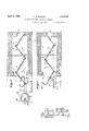
- Fig. 1 is a side elevation showing how the invention is applied to a furnace, the showing of the furnace bein substantially diagrammatic and merely for the purpose of illustration.
- Fig. 2 is a vertical transverse section taken on the line 2-2 of Fig. 1.
- Fig. 8 is a vertical longitudinal section taken substantially on the line 3-3 of Fig. 2.
- Fig. 4 is a view similar to Fig. 3 showing the conveyer parts at the opposite limits of their movement from that shown in Fig. 3.
- Fig. 5 is a plan View illustrating a pair of adjacent plate members having overlapping edge portions which are recessed to receive the overlapping portions of the adjacent plate member.
- Fig. 6 is an end elevation of the plate member s own in Fig. 5.
- a heat treating furnace is indicated at 1 and is substantially diagrammatic, for the purpose of showing how the invention is mounted in relation to.'a furnace construction. The details of the furnace construction are therefore omitted.
- the furnace includes generally the heat treatingchamber 2 having a chzrging opening 3 and a discharge openmg
- the improved conveyer construction of this invention includes a plurality of plate members 5 which are mounted in the heating chamber 2 of the furnace to extend transversely thereof as clearly shown in the drawings. These plate members 5 are mounted so that a portion of the opposite sides of the adjacent members will over-lap a substantial amount.
- Each of the plate members 5 is provided with trunnions 6 extending from opposite ends, and each have their axes in alignment and projecting from the ends of the plate members along the median longitudinal dimension thereof.
- each plate member is journalled in the side walls of the furnace 1 in suitable bearing openings in order that the plates will be adapted for rocking movement.
- Corresponding edge portions of each plate member are curved downwardly as indicated at 7, while the opposite edge portions of each plate member are curved upwardly as indi cated at 8.
- a downwardly curved portion 7 on one member engages over the upwardly curved portion 8 of the adjacent plate member, so that these curved portions have interfitting cooperation in addition to the overlapping of the edges of the plate members.
- Alternate plate members 5 have the trunnions 6 extending beyond one side wall of the furnace and provided with crank arms 9, the free ends of which are connected by the bar member 10.
- a connecting rod 11 is pivotally connected at one end to one of the arms 9 and bar member 10 and at the opposite end is connected to the crank arm 12 on the drive shaft 13 rotatably mounted in suitable bearings 14:.
- the alternate plates are simultaneously rocked first in one direction, then in the other.
- the intermediate plate members 5 extending between the alternate plate members above described have their trunnions 6 extending beyond the opposite side of the furnace and provided with crank arms 15.
- crank arms are connected by a bar member 16, while a pitman 17 connects the bar member with a slide member 18 mounted for sliding movement in the bearin member 19.
- the opposite end of this sli e member 18 is provided with a laterally extending pin engaged in the cam groove 20 of cam member 21.
- This cam member 21 is mounted on the drive shaft 13 and the cam groove is formed, so that the intermediate plate members W111 be rocked simultaneously with the alternate plate members, in a direction opposite thereto, and ve a differential movement relative to said a ternate plate members, for the purpose of maintaining the free edges of the intermediate plate members in substantially constant engagement with the alternate plate members throughout the entire rocking movement of said members.
- the downwardly curved edge of one plate member which extends over the upwardly curved edge of the adjacent plate member on its movement from the lower positionsuch as shown in Fig. 3, to its opposite limit of movement as shown in Fig. 4 engages the articles in the V-shaped trough as shown in Fig. 3 and on the movement of the plates to the position shown in Fig. 4, pushes the articles a slight amount to start their rolling and sliding downwardly over the plate formed with the upturned edge above referred to, as it reaches the inclined position shown in Fig. 4 with the upturned edge at its upper limit of movement.
- a special plate member is provided at the charging opening 3 as indicated at 22 having its free edge provided with the upstanding flange 23 which is adapted in the position shown in Fig. 4 to receive a charge of material to be heat treated, so that on the next stroke of movement of the plates, it will be caused to slide downwardly into the trough formed between the first and second plates as shown in Fig. 3 and subsequently fed through the heating chamber of the furnace in the manner above described.
- the plate member at the discharge end is similar in all respects to the plate members 5 with the exception that the free edge portion is not provided with the downwardly curved portion.
- the plates are still constructedwith the edges in overlapping inter-fitting relation as above described and may be formed as illustrated in Figs. 5 and 6 in which the adjacent edges of adjacent plates are recessed as indicated at 24 in staggered relation so that the projections 25 having the curved ends 26 on each plate will register with the recesses in the adjacent plate.
- the down wardly curved edges will still perform their feeding cooperation with the upwardly curved edges as above describedin order'to feed the articles to be heat treated across the plate members in one direction only.
- a plurality of plate members mounted in transversely extending adjacent relation in said furnace with the opposite edges of each member curved in opposite directions, said curved edges of each plate member having overlapping interfitting cooperation with the edges of adjacent plate members, means for oscillating said plate members having connection with alternate platesindependent of intermediate plates, and adapted to rock the alternate plates in a direction opposite to the intermediate plates during the oscillating movement, for feeding material supported on the plates from posite edges of each member curved in op- I posite directions, said curved edges of each plate member having overlapping inter-fitting cooperation with edges of adjacent plate members, means connecting alternate plate members for simultaneous rocking movement in one direction, means connecting intermediate plate members for simultaneous rocking movement in an opposite direction to said intermediate plate members, and operating means for producing a differential movement of the last two named means in oscillating said plate members, said difierential movement retaining said plate members in substantial contact, said curved edges cooperat ing to feed material
- a conveyer for heat treating furnaces having charging and discharge openings at opposite ends, comprising a plurality of plate members mounted in transversely extending adjacent relation, and having the opposite edges of each member curved in opposite directions, said curved edges having overlapping cooperation, and means adapted to rock alternate plate members in one direction and intermediate plate members in an opposite direction simultaneously, for feeding articles thereover, said means retaining said plate members in adjacent overlapping contiguous relation.
- a conveyer comprising a plurality of plate members mounted for rocking movement about fixed axes and extending in ad jacent relation, transversely of the direction of feed for articles, and having overlapping and inter-fitting adjacent edge portions for controlling feedof articles thereover, and
Landscapes
- Engineering & Computer Science (AREA)
- Mechanical Engineering (AREA)
- General Engineering & Computer Science (AREA)
- Tunnel Furnaces (AREA)
- Heat Treatments In General, Especially Conveying And Cooling (AREA)
Description
Aprifi 8, 1930 c: A. BARRETT H 1,753,679
CONVEYER FOR HEAT TREATING FURNACES Filed 001:. 26, 1927 2 Sheets-Sheet l C. A. BARRETT Apr'i 8, 1930.
CONVEYER FOR HEAT TREATING FURNACES Filed Oct. 26, 1927 2 Sheets-Sheet Patented Apr. 8, 1930 ITED STATES CHARLES A. BARRETT, OF BUFFALO, NEW YORK CONVEYER FOR HEAT-TREATING FURNACES Application filed October 26, 1927. Serial No. 228,892.
This invention relates generally to convey ries the material for heat treatment therein,
while a greater portion of the conveyer idles during the return movement after discharging heated material, to receive a new charge of material to be treated. It is customary to have this return portion of the conveyer exterior of the heat treating chamber of the furnace. As a result, conveyer sections are constantly travelling through the heating zone and heated to a substantial temperature, after which they are returned through the atmosphere Where they become cool and upon re-entering the heat chamber must be reheated. This operation occasions a substantial loss of heat in addition to a substantial amount of wear on a conveyer, due to the constant heating and cooling of theparts thereof. The present invention is designed to eliminate the use of endless conveyers in heat treating furnaces and the like, and overcome the difiiculties which are experienced in the use of such conveyors.
To this end the invention comprehends the provision of a conveyer structure which is contained within the heating chamber of the furnace and constantly maintained at the same temperature as the interior of the furnace, while it is operated to convey material for heat treatment.
The invention further provides a construction by which material for heat treatment can be constantly fed through a furnace in substantially uniform quantities so as to obtain an even heat treatment of all of the material.
An important feature of the invention resides in providing a plurality of plate members extending transversely of a furnace in adjacent relation and having the adjacent edges overlap ing, so that in the rocking movement of t e plate members, these edges will co-operate to control and feed material over the plate members. The invention comprehends numerous other objects residing in the details of construction and relation of the parts which form the conveyer structure, all of which are more particularly pointed out in the following detailed description and claims directed to a preferred form of construction, it being understood however, that variations in the size, shape and relation of these parts may be made without departing from the spirit and scope of the invention as herein set forth.
In the drawings forming part of this application:
Fig. 1 is a side elevation showing how the invention is applied to a furnace, the showing of the furnace bein substantially diagrammatic and merely for the purpose of illustration.
Fig. 2 is a vertical transverse section taken on the line 2-2 of Fig. 1.
Fig. 8 is a vertical longitudinal section taken substantially on the line 3-3 of Fig. 2.
Fig. 4 is a view similar to Fig. 3 showing the conveyer parts at the opposite limits of their movement from that shown in Fig. 3.
Fig. 5 is a plan View illustrating a pair of adjacent plate members having overlapping edge portions which are recessed to receive the overlapping portions of the adjacent plate member.
Fig. 6 is an end elevation of the plate member s own in Fig. 5.
A heat treating furnace is indicated at 1 and is substantially diagrammatic, for the purpose of showing how the invention is mounted in relation to.'a furnace construction. The details of the furnace construction are therefore omitted. The furnace includes generally the heat treatingchamber 2 having a chzrging opening 3 and a discharge openmg The improved conveyer construction of this invention includes a plurality of plate members 5 which are mounted in the heating chamber 2 of the furnace to extend transversely thereof as clearly shown in the drawings. These plate members 5 are mounted so that a portion of the opposite sides of the adjacent members will over-lap a substantial amount. Each of the plate members 5 is provided with trunnions 6 extending from opposite ends, and each have their axes in alignment and projecting from the ends of the plate members along the median longitudinal dimension thereof. These trunnions are journalled in the side walls of the furnace 1 in suitable bearing openings in order that the plates will be adapted for rocking movement. Corresponding edge portions of each plate member are curved downwardly as indicated at 7, while the opposite edge portions of each plate member are curved upwardly as indi cated at 8. A downwardly curved portion 7 on one member engages over the upwardly curved portion 8 of the adjacent plate member, so that these curved portions have interfitting cooperation in addition to the overlapping of the edges of the plate members.
Alternate plate members 5 have the trunnions 6 extending beyond one side wall of the furnace and provided with crank arms 9, the free ends of which are connected by the bar member 10. A connecting rod 11 is pivotally connected at one end to one of the arms 9 and bar member 10 and at the opposite end is connected to the crank arm 12 on the drive shaft 13 rotatably mounted in suitable bearings 14:. In the rotation of the drive shaft 13 from any suitable source of power (not shown), it will be obvious that the alternate plates are simultaneously rocked first in one direction, then in the other. The intermediate plate members 5 extending between the alternate plate members above described have their trunnions 6 extending beyond the opposite side of the furnace and provided with crank arms 15. These crank arms are connected by a bar member 16, while a pitman 17 connects the bar member with a slide member 18 mounted for sliding movement in the bearin member 19. The opposite end of this sli e member 18 is provided with a laterally extending pin engaged in the cam groove 20 of cam member 21. This cam member 21 is mounted on the drive shaft 13 and the cam groove is formed, so that the intermediate plate members W111 be rocked simultaneously with the alternate plate members, in a direction opposite thereto, and ve a differential movement relative to said a ternate plate members, for the purpose of maintaining the free edges of the intermediate plate members in substantially constant engagement with the alternate plate members throughout the entire rocking movement of said members. If no differential movement were rovided between the plate members as just escribed, the free edges ofone plate member would move relative to the other in such a way, that throughout a portion of the cycle of movement of the plate members, the edges would be spaced apart a suflicient distance to permit small articles to fall between the plate members into the bottom of the furnace. This conveyer is constructedto operate as above described, so that small articles such as rods, bolts, nuts and the like may be carried thereby for heat treatment in the furnace and be efliciently fed from one end of the furnace to the other during this treatment. In the oscillating movement of these plate members through the rotation of shaft 13, the overlapping inter-fitting curved edges of the plate members cooperate to positively feed the material across the plate members. In this cooperation, the downwardly curved edge of one plate member which extends over the upwardly curved edge of the adjacent plate member on its movement from the lower positionsuch as shown in Fig. 3, to its opposite limit of movement as shown in Fig. 4 engages the articles in the V-shaped trough as shown in Fig. 3 and on the movement of the plates to the position shown in Fig. 4, pushes the articles a slight amount to start their rolling and sliding downwardly over the plate formed with the upturned edge above referred to, as it reaches the inclined position shown in Fig. 4 with the upturned edge at its upper limit of movement. In this way, the material on the first two plates is fed across the second plate to engage in the shaped trough formed between the second and third plates and in the next movement of the plate members 5, this material is fed across the next plate and so on until it is discharged through the opening 4. In this operation, these curved inter-fitting edges Wlll thereby efliciently control and feed material over the plates and prevent small articles being heat treated from dropping into the furnace between the plates.
A special plate member is provided at the charging opening 3 as indicated at 22 having its free edge provided with the upstanding flange 23 which is adapted in the position shown in Fig. 4 to receive a charge of material to be heat treated, so that on the next stroke of movement of the plates, it will be caused to slide downwardly into the trough formed between the first and second plates as shown in Fig. 3 and subsequently fed through the heating chamber of the furnace in the manner above described. The plate member at the discharge end is similar in all respects to the plate members 5 with the exception that the free edge portion is not provided with the downwardly curved portion.
- \Vhere substantially large articles are to be heat treated, such as rollers, cylinders and the like, it is not necessary that the plates have their edges operated in substantial bearing contact, so that the use of the cam 21 may be dispensed with on furnaces designed for large work. In such a case, the plates are still constructedwith the edges in overlapping inter-fitting relation as above described and may be formed as illustrated in Figs. 5 and 6 in which the adjacent edges of adjacent plates are recessed as indicated at 24 in staggered relation so that the projections 25 having the curved ends 26 on each plate will register with the recesses in the adjacent plate. In this way, a slight difference in movement between the plates which occurs whenthe cam is eliminated and the plates operated directly through cranks or other suitable means, will be compensated for. With this form of construction,'the down wardly curved edges will still perform their feeding cooperation with the upwardly curved edges as above describedin order'to feed the articles to be heat treated across the plate members in one direction only.
With a conveyer construction of this character, it will be seen that all of the plates within the heating chamber are maintained at a constant temperature as a result of which there is no loss of heat, as in the case of an endless conveyer, and a more even heat of the articles to be heated can be obtained as a result of having these conveyer plates in the constantly heated condition. In addition, a substantial saving in material is effected and while uniformity of operation of the conveyer is obtained as a result of which, proper alloys may be used which have known wear this way, a substantial saving can be effected in the construction and operation of this conveyer over the endless type.
What is claimed is 1. In a heat treating furnace having charging and discharge openings at the forward and rear ends respectively, a plurality of plate members mounted in transversely extending adjacent relation in said furnace with the opposite edges of each member curved in opposite directions, said curved edges of each plate member having overlapping interfitting cooperation with the edges of adjacent plate members, means for oscillating said plate members having connection with alternate platesindependent of intermediate plates, and adapted to rock the alternate plates in a direction opposite to the intermediate plates during the oscillating movement, for feeding material supported on the plates from posite edges of each member curved in op- I posite directions, said curved edges of each plate member having overlapping inter-fitting cooperation with edges of adjacent plate members, means connecting alternate plate members for simultaneous rocking movement in one direction, means connecting intermediate plate members for simultaneous rocking movement in an opposite direction to said intermediate plate members, and operating means for producing a differential movement of the last two named means in oscillating said plate members, said difierential movement retaining said plate members in substantial contact, said curved edges cooperat ing to feed material in one direction over said plate members.
3. A conveyer for heat treating furnaces having charging and discharge openings at opposite ends, comprising a plurality of plate members mounted in transversely extending adjacent relation, and having the opposite edges of each member curved in opposite directions, said curved edges having overlapping cooperation, and means adapted to rock alternate plate members in one direction and intermediate plate members in an opposite direction simultaneously, for feeding articles thereover, said means retaining said plate members in adjacent overlapping contiguous relation. I V
4. A conveyer comprising a plurality of plate members mounted for rocking movement about fixed axes and extending in ad jacent relation, transversely of the direction of feed for articles, and having overlapping and inter-fitting adjacent edge portions for controlling feedof articles thereover, and
means adapted to rock alternate plate members in one direction and intermediate plate members in an opposite direction simultaneously, said means retaining edge portions of adjacent plate membersin substantial con tact with adjacent portions of said adjacentplate members.
CHARLES -A. BARRETT.
the charging to the discharge opening through said furnace, said curved edges causing material on said plates to move only in one dlrection, and means for providing a relative differential movement. of alternate plates with respect to intermediate plates for maintaining said plates in substantially adjacent contacting relation throughout the oscillating movement thereof.
2. In a heat treating furnace having charging and discharge openings at the forward and rear ends respectively, a plurality of plate membersmounted in transversely extending adjacent relation in said furnace with the op-
Priority Applications (1)
| Application Number | Priority Date | Filing Date | Title |
|---|---|---|---|
| US228892A US1753679A (en) | 1927-10-26 | 1927-10-26 | Conveyer for heat-treating furnaces |
Applications Claiming Priority (1)
| Application Number | Priority Date | Filing Date | Title |
|---|---|---|---|
| US228892A US1753679A (en) | 1927-10-26 | 1927-10-26 | Conveyer for heat-treating furnaces |
Publications (1)
| Publication Number | Publication Date |
|---|---|
| US1753679A true US1753679A (en) | 1930-04-08 |
Family
ID=22858972
Family Applications (1)
| Application Number | Title | Priority Date | Filing Date |
|---|---|---|---|
| US228892A Expired - Lifetime US1753679A (en) | 1927-10-26 | 1927-10-26 | Conveyer for heat-treating furnaces |
Country Status (1)
| Country | Link |
|---|---|
| US (1) | US1753679A (en) |
Cited By (2)
| Publication number | Priority date | Publication date | Assignee | Title |
|---|---|---|---|---|
| US3774746A (en) * | 1971-04-08 | 1973-11-27 | Sunkist Growers Inc | Conveyor with rocking units to roll round articles |
| US5201400A (en) * | 1991-01-25 | 1993-04-13 | Isowa Industry Co., Ltd. | Apparatus for conveying roll-shaped article |
-
1927
- 1927-10-26 US US228892A patent/US1753679A/en not_active Expired - Lifetime
Cited By (2)
| Publication number | Priority date | Publication date | Assignee | Title |
|---|---|---|---|---|
| US3774746A (en) * | 1971-04-08 | 1973-11-27 | Sunkist Growers Inc | Conveyor with rocking units to roll round articles |
| US5201400A (en) * | 1991-01-25 | 1993-04-13 | Isowa Industry Co., Ltd. | Apparatus for conveying roll-shaped article |
Similar Documents
| Publication | Publication Date | Title |
|---|---|---|
| US2487354A (en) | Conveyer for changing course of articles from single to plural rows | |
| US1753679A (en) | Conveyer for heat-treating furnaces | |
| US3322414A (en) | Conveyor apparatus | |
| US1523971A (en) | Apparatus for treating briquettes | |
| US2045957A (en) | Conveyer for baking ovens | |
| US1937416A (en) | Process of roasting pimiento peppers and the like | |
| US3144245A (en) | Heat treating furnaces | |
| US1941599A (en) | Conveyer type of pair or pack furnace | |
| US1696822A (en) | Continuous furnace | |
| GB1584894A (en) | Combination of tunnel-type kiln and monolayer truck | |
| US1858484A (en) | Conveyer | |
| US1696900A (en) | baily | |
| US1799956A (en) | Material conveyer for furnaces | |
| US1393003A (en) | Drying apparatus | |
| US3570827A (en) | High temperature roller conveyor | |
| US3374996A (en) | Method and apparatus for conveying workpieces | |
| US1384311A (en) | Cooling-tank | |
| US1649926A (en) | Conveyer | |
| US2006832A (en) | Cooking apparatus | |
| US761088A (en) | Drying-kiln. | |
| US1852664A (en) | Conveyer and operating mechanism therefor | |
| US2214234A (en) | Ingot furnace | |
| US1405762A (en) | Furnace | |
| US2142824A (en) | Furnace conveyer and method of treatment | |
| US662910A (en) | Apparatus for applying coatings. |