US1753677A - Metal-working process and apparatus - Google Patents
Metal-working process and apparatus Download PDFInfo
- Publication number
- US1753677A US1753677A US127732A US12773226A US1753677A US 1753677 A US1753677 A US 1753677A US 127732 A US127732 A US 127732A US 12773226 A US12773226 A US 12773226A US 1753677 A US1753677 A US 1753677A
- Authority
- US
- United States
- Prior art keywords
- tube
- tool
- head
- metal
- pilot
- Prior art date
- Legal status (The legal status is an assumption and is not a legal conclusion. Google has not performed a legal analysis and makes no representation as to the accuracy of the status listed.)
- Expired - Lifetime
Links
- 238000000034 method Methods 0.000 title description 34
- 238000005555 metalworking Methods 0.000 title description 7
- 239000011324 bead Substances 0.000 description 14
- 230000003116 impacting effect Effects 0.000 description 12
- 239000002184 metal Substances 0.000 description 10
- 229910052751 metal Inorganic materials 0.000 description 10
- 238000005096 rolling process Methods 0.000 description 6
- 238000009527 percussion Methods 0.000 description 4
- 238000005336 cracking Methods 0.000 description 3
- 230000000694 effects Effects 0.000 description 3
- 230000008961 swelling Effects 0.000 description 3
- 229910000831 Steel Inorganic materials 0.000 description 2
- 238000010438 heat treatment Methods 0.000 description 2
- 239000010959 steel Substances 0.000 description 2
- 230000003313 weakening effect Effects 0.000 description 2
- RYGMFSIKBFXOCR-UHFFFAOYSA-N Copper Chemical compound [Cu] RYGMFSIKBFXOCR-UHFFFAOYSA-N 0.000 description 1
- 244000182067 Fraxinus ornus Species 0.000 description 1
- 241000287227 Fringillidae Species 0.000 description 1
- 102100034742 Rotatin Human genes 0.000 description 1
- 101710200213 Rotatin Proteins 0.000 description 1
- 230000006978 adaptation Effects 0.000 description 1
- 238000010276 construction Methods 0.000 description 1
- 238000010924 continuous production Methods 0.000 description 1
- 229910052802 copper Inorganic materials 0.000 description 1
- 239000010949 copper Substances 0.000 description 1
- 238000005260 corrosion Methods 0.000 description 1
- 230000007797 corrosion Effects 0.000 description 1
- 238000003780 insertion Methods 0.000 description 1
- 230000037431 insertion Effects 0.000 description 1
- 238000009434 installation Methods 0.000 description 1
- 238000010409 ironing Methods 0.000 description 1
- 230000001788 irregular Effects 0.000 description 1
- 235000015250 liver sausages Nutrition 0.000 description 1
- 238000012986 modification Methods 0.000 description 1
- 230000004048 modification Effects 0.000 description 1
- 239000003208 petroleum Substances 0.000 description 1
- 238000007670 refining Methods 0.000 description 1
- XYSQXZCMOLNHOI-UHFFFAOYSA-N s-[2-[[4-(acetylsulfamoyl)phenyl]carbamoyl]phenyl] 5-pyridin-1-ium-1-ylpentanethioate;bromide Chemical compound [Br-].C1=CC(S(=O)(=O)NC(=O)C)=CC=C1NC(=O)C1=CC=CC=C1SC(=O)CCCC[N+]1=CC=CC=C1 XYSQXZCMOLNHOI-UHFFFAOYSA-N 0.000 description 1
- 238000009987 spinning Methods 0.000 description 1
- 238000003466 welding Methods 0.000 description 1
Images


Classifications
-
- B—PERFORMING OPERATIONS; TRANSPORTING
- B21—MECHANICAL METAL-WORKING WITHOUT ESSENTIALLY REMOVING MATERIAL; PUNCHING METAL
- B21D—WORKING OR PROCESSING OF SHEET METAL OR METAL TUBES, RODS OR PROFILES WITHOUT ESSENTIALLY REMOVING MATERIAL; PUNCHING METAL
- B21D39/00—Application of procedures in order to connect objects or parts, e.g. coating with sheet metal otherwise than by plating; Tube expanders
- B21D39/06—Application of procedures in order to connect objects or parts, e.g. coating with sheet metal otherwise than by plating; Tube expanders of tubes in openings, e.g. rolling-in
-
- Y—GENERAL TAGGING OF NEW TECHNOLOGICAL DEVELOPMENTS; GENERAL TAGGING OF CROSS-SECTIONAL TECHNOLOGIES SPANNING OVER SEVERAL SECTIONS OF THE IPC; TECHNICAL SUBJECTS COVERED BY FORMER USPC CROSS-REFERENCE ART COLLECTIONS [XRACs] AND DIGESTS
- Y10—TECHNICAL SUBJECTS COVERED BY FORMER USPC
- Y10T—TECHNICAL SUBJECTS COVERED BY FORMER US CLASSIFICATION
- Y10T29/00—Metal working
- Y10T29/49—Method of mechanical manufacture
- Y10T29/4935—Heat exchanger or boiler making
- Y10T29/49387—Boiler making
-
- Y—GENERAL TAGGING OF NEW TECHNOLOGICAL DEVELOPMENTS; GENERAL TAGGING OF CROSS-SECTIONAL TECHNOLOGIES SPANNING OVER SEVERAL SECTIONS OF THE IPC; TECHNICAL SUBJECTS COVERED BY FORMER USPC CROSS-REFERENCE ART COLLECTIONS [XRACs] AND DIGESTS
- Y10—TECHNICAL SUBJECTS COVERED BY FORMER USPC
- Y10T—TECHNICAL SUBJECTS COVERED BY FORMER US CLASSIFICATION
- Y10T29/00—Metal working
- Y10T29/49—Method of mechanical manufacture
- Y10T29/49826—Assembling or joining
- Y10T29/49908—Joining by deforming
- Y10T29/49938—Radially expanding part in cavity, aperture, or hollow body
- Y10T29/4994—Radially expanding internal tube
-
- Y—GENERAL TAGGING OF NEW TECHNOLOGICAL DEVELOPMENTS; GENERAL TAGGING OF CROSS-SECTIONAL TECHNOLOGIES SPANNING OVER SEVERAL SECTIONS OF THE IPC; TECHNICAL SUBJECTS COVERED BY FORMER USPC CROSS-REFERENCE ART COLLECTIONS [XRACs] AND DIGESTS
- Y10—TECHNICAL SUBJECTS COVERED BY FORMER USPC
- Y10T—TECHNICAL SUBJECTS COVERED BY FORMER US CLASSIFICATION
- Y10T29/00—Metal working
- Y10T29/53—Means to assemble or disassemble
- Y10T29/53709—Overedge assembling means
- Y10T29/53717—Annular work
Definitions
- This invention relates to metal working and includes bothprocess and apparatus.
- it relates to the installation or securing of tubular .members in apertured heads such as in tube or flue setting for boil ers, stills, etc.
- outer projecting end of the tube is then flared either by a separate tool or. as the part of the rolling step.
- the flared endof the tube is then formed into a bead by means of a manwith the greatest care on the part of the most skilled workman there is a tendency tothin the wall of the tube at the turn of the bead,
- Another object is to perform the flue setting operations, or any desired number of them, in one continuous operation.
- a further object is to eliminate entirely the heating of'heavy tubes.
- a still further object is to simplify the work and to reduce the number of men required to perform it.
- Still another object is to reduce the mechanical equipment required.
- the invention consists in an; improvedprocessby which all or most of the steps of the usual method are performed with very littlemanual labor and with agreatlyreduced force ofmen.
- the end of'the tube and its interior is subjected to a continuous operationin volving both percussion and rotation. It further consists in'impacting thetube metal into the walls of the head opening to insure v. a tight joint. This may be accomplished by maintaining the tube Walls at and adjacent the bead of uniform thickness while the end of the tube is subjected to percussion; It
- V ods are used.
- the invention further consists in suitable apparatus for producing the above results.
- the actualworking tool may take the form of a relatively thick flat member with two or more tube engaging portions arranged to enter the tube and to receive a large number of heavy blows per minute and to be rotated at the same time so that a spinning, ironing, or rolling eflect is produced upon the interior of the tube.
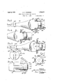
- Fig. 1 is a perspective view of a workman putting down a boiler tube accordance with the improved process
- I i i Fig. 2 is a fragmentary view on an enlarged scale of the apparatus shown in Fig. 1, a portion of the boiler. head and tube being shown in section, also a portion ofthe percussive and rotative machine, while the working tool is shown in side elevation en tering the tube w Figs. 8, 4, and .5, are fragmentary views similar to Fig. 2, but on an enlarged scale illustrating stages in;
- the process of setting the tube r Fig. 6 is a. right hand elevational View of the working tool shown in the previous figures with the pilot member removed;
- Figs. 7 and 8 are respectively a right hand elevational view and a sidewelevational view of a modified formof tool
- Fig. 9 is a sectional view through the wall of a still illustrating a modified form of tool
- Fig. 10 is a side elevational view of the working tool shown in Fig. 9;
- Fig. 11 is a view similar toFig. 9 illustrating the process as applied to the setting of tubes in. a Burton still;
- Fig. 12 is a fragmentary side elevational viewv ofthe working tool shown in Fig. 11.
- Fig. 1 illustrates the improved process whereinthe operator A is directing a percussive and rotative machine B provided with a working tool 13 inthe setting of tubes in a boiler or still head C. Tubes 14 have been placed in the apertures therefor in head C preparatory to being secured therein, certain of the tubes being shown with a completed head at 14?;
- Machine B maybe of any suitable or desired. type; it isprovided with a rotatable chuck '72 in which the shank end 13 of the working tool 13 is inserted (Fig. 2) to receive the blows of a percussive member such as piston I) while the chuck b is rotated either continuously or intermittently by any known or suitable apparatus actuated as a result of the reciprocatory movement of pisofthe continuous process by which tubes 14 trance into the tube followed-by the diametrically opposed expanding surfaces 13. The expanding surfaces are followed by the tube holding surfaces 13 after which come the beading sockets 13 terminating in stops 13. i The Ieadingedges of the expanding and holdingsurfaces are beveled as indicated in Fig.
- a suitable pilot is. preferably provided, at the front of the tool, this pilot being omitted in the end elevational view Fig.6 for the sakeof clearness.
- the pilot nay take the'form of' a cylinder 13 loosely fitting the interior of the tube and either rotatable upon or permanently fixed to a reduced extension 13 of the tool. If the pilot is rotatably mounted it should be' secured; to extension 13 in a mannerto resist the heavy vibration resulting from the operation of machine B which 1 tends to shear ofi' cotter-pins and-similar securing devices.
- a preferred arrangement is I to apply a washer 133 and then form the end of the extension into a rivet head 13 If the pilot is to be a permanent part of the tool it may be fashioned initially as an integral part ofthe tool or be secured there-to l in any suitable manner as by welding.
- Fig. 2 shows the work- 'ing tool 13 just being inserted within the. tube.
- Machine Bis then started delivering heavy blows to the shank end ofthe working tool and at, the same time rotatin the tool.
- This rotation maybe, continuous iI an independentrotating-motoris used as a part of machine B or alternating with the blows if the rotating efiect results from mechanism operated by the reciprocations of the piston.
- FIG. 3 shows the tool advanced to the point where the beadingrecess 13 is beginningto flare the outerend ofthe tube. At this point the imacting'action of the process begins, since the heavy blows of the percussive machineare-now deliveredto the outer tighter oint.
- the action of the flaring surfaces 13 produces the effect of the preliminary interior rolling of the tube in the ordinary hand methods.
- the flaring and beading of the tube is accomplished by the beading recesses 13";
- the finishing roll of theordinary hand methods is entirely obviated by the action of the holding surfaces 13 which produce an actual impacting of the metal and a much.
- the finish roll of the tub in the hand-process is for the purpose of tightening the joint, but real impacting of the metal is not secured since percussion is lackpreviously described secures and maintains a uniform thickness of the tube Wall, a result which is never accomplished and in fact is quite impossible with the prior hand-processes.
- Tool has a reduced entering portion 15", expanding surfaces 15, holding surfaces 15 beading recesses 15*, stops15 and an extension 15 carrying a pilot 15 which may be held as
- the improved process as in thecase 'of thefirstltoolby afwasher 15; and rivethead 15 Byreason of the greater number 9f engaging surfaces for the tubethe pilot 15 may be quite small, or dispensed with entirely, but more satisfactory operation is secured witlra large pilot as indicated.”
- the manner of using tool'15 and theeflfects pro prised thereby are identical with tool 13.
- Figs. 9 to 12 disclose tools for usein the setting of tubes in oil stills.
- Such stills have an inner aperturedhead "or tubefsheet 16 in which the tubes 17 are securedfand an outer head 18 in s pa'ced relationto-head lfi with hand-holes or openings 18Ktherethroi1'gl1. While these hand-openings are ordinarily somewhat larger than the tube openings,they
- Tool 19 is'similar to tool13 in that it is ofthe two-bladed type, but has only one. beading projection 19*.
- the still disclosed inFig'. 9 is intended foruse' withlarge diameter tubes having thick walls, a hal'f'inch or more in thickness. l/Yhile the present invention contemplates the use of a tool which will expand, flare and y bead the .tube in one continuous operation,
- That step in the process of securing a tubular member having athick wall in an apertured head which involves the calking of the member to the head by thelateral impacting of the member into the head within the aperture, said step comprising delivering blows to the end of the member adjacent the aperture and supporting the interior of the member against internal swelling or distortion within the aperture by rigid unyielding means.
- blades rearwardly of said pilot presentingangularly inclined radially disposed surfaces for expanding the interior of the tube, at least one of said blades having surfaces for turning a bead upon the end of the tube, said blades having holding surfaces for rigidly maintain ing the thickness of the Wall of the tube within the head substantially uniform during the heading operation. 7 v n 10.
- a metal working tool for setting thick- 7 walled tubular members having a shank arranged to receive blows and means at the opposite end for beading a tubular member in a head and for calking the member in the head with a lateral impacting effect.
- a tool for setting thick-walled tubes in boilers, stills, and the like having a shank to receive rotative and percussive impulses, a pilot at the opposite end to enter a tube and blades rearwardly of said pilot having surfaces for expanding, flaring and beading the tube and for holding the tube against internal distortion during the beading operation thereby to produce a lateral impacting efi'ect i and a calked joint.
Landscapes
- Engineering & Computer Science (AREA)
- Mechanical Engineering (AREA)
- Metal Extraction Processes (AREA)
Description
April 8, 1930.
A. C. ANDRESEN METAL WORKING PROCESS AND APPARATUS Filed Aug. 7, 1926 3 Sheets-Sheet 1 A TTORNEY.
A. c. ANDRESEN 1,753,677 METAL- WORKING PROCESS AND APPARATUS Filed Aug. 7, 1926 5 Sheets-Sheet 2 d .3 {39 ll r INVENTOR ADOLPH QANDRESEN A TT ORNE Y April 8, 1930. A. c. ANDRESEN 1,753,677
METAL WORKING PROCESS AND APPARATUS Filed Aug. *7. 1926 5 Sheets$f1et s A TTORNE Y Patented Apr, 8, 1930 I UNITED STATES PATE T L FF-ICE? ADOLPH c. ennnnsnn, or NEW YORK, n. n, Assrenon To CHICAGO.- ma rooL commmy, on NEW xorax, 1v. Y., A CORPORATION ornnwunrasny 1 I g METAL-WORKING rnoonss ANDQAIPPARATUS- Application filed Aiigust 7; 1926. SeriaI NoL 127,732.
This invention relates to metal working and includes bothprocess and apparatus. In particular it relates to the installation or securing of tubular .members in apertured heads such as in tube or flue setting for boil ers, stills, etc.
Processes heretofore in use have been characterized by a large expenditure of physical labor andseveral separate steps or operatlons. In boiler making, for example, in the installing of a tube the first step is to roll the: in-
terior of the tube so as to expand itinto contact with the walls of the head opening. The
outer projecting end of the tube is then flared either by a separate tool or. as the part of the rolling step. The flared endof the tube is then formed into a bead by means of a manwith the greatest care on the part of the most skilled workman there is a tendency tothin the wall of the tube at the turn of the bead,
with the result that the tube is weakend at this point. In fact, any tube put down by hand methods such as heretofore practlced,
when sectioned will be found to have. a wall of varying and irregular thickness at and adjacent the bead; In order to remedy at der to assist in securing a tight joint.
In the construction of stills used 1n the socalled cracking processes 1n the refining of petroleum, the difficulties encountered in boiler and ordinary still work are greatly magnifiedfor the reason that the trade is demanding in the interests of economy larger T and larger stills with very heavy walls in or der'to'delay and postpone the inevitable reout of the metal of the stills. At the'present time cracking stills'are being made with All the tools used are manually di ther object is to avoid the diificulties of prior steel tubes having an inner diameterof 3 to {finches and an exterior diameter of l to 5 inches, the walls of the tubes being inch 1 thick. P-resent methods of installing such tubes require the use of the-heaviest portable tool equipment obtainable, and additional operative steps by reason of thethickness ofthe walls of the tubes worked upon, ins cluding-heating the tubes tomake the metal more ductile, also a large crew of men is required by reason of the extremely laborious l nature of the work. Such stills usually h ave an outer wall or head spaced fromthe flue; head and the work must be performed through small hand-openings in the outer wall, which makes the work still more difli cult to perform and to 'checkbydnspection. Among the objects of the invention are to improve the quality of the work and tore- I v I duce the labor, time and: expense of securing tubular members in place.- Another object is to perform the flue setting operations, or any desired number of them, in one continuous operation. A further object is to eliminate entirely the heating of'heavy tubes. A still further object is to simplify the work and to reduce the number of men required to perform it. Still another object is to reduce the mechanical equipment required. A still furmethods and to improve the resistance of the joint 'to pressure, corrosion and strains Other objects Wlll be apparent from the'de tailed description-which follows least in part the difficulties of such methods it is customary to line the head opening witha ferruleof soft metal such as copper in or-- In one aspect the invention consists in an; improvedprocessby which all or most of the steps of the usual method are performed with very littlemanual labor and with agreatlyreduced force ofmen. In practicing the process the end of'the tube and its interior is subjected to a continuous operationin volving both percussion and rotation. It further consists in'impacting thetube metal into the walls of the head opening to insure v. a tight joint. This may be accomplished by maintaining the tube Walls at and adjacent the bead of uniform thickness while the end of the tube is subjected to percussion; It
. avoids thinning and weakening the tubead- V j acent t'he head as when ordinary hand-meth-.
V ods are used. The invention further consists in suitable apparatus for producing the above results. The actualworking tool may take the form of a relatively thick flat member with two or more tube engaging portions arranged to enter the tube and to receive a large number of heavy blows per minute and to be rotated at the same time so that a spinning, ironing, or rolling eflect is produced upon the interior of the tube.
The invention is" illustrated by the accompanying drawings in which:
Fig. 1 is a perspective view of a workman putting down a boiler tube accordance with the improved process; I i i Fig. 2 isa fragmentary view on an enlarged scale of the apparatus shown in Fig. 1, a portion of the boiler. head and tube being shown in section, also a portion ofthe percussive and rotative machine, while the working tool is shown in side elevation en tering the tube w Figs. 8, 4, and .5, are fragmentary views similar to Fig. 2, but on an enlarged scale illustrating stages in; the process of setting the tube r Fig. 6 is a. right hand elevational View of the working tool shown in the previous figures with the pilot member removed;
Figs. 7 and 8 are respectively a right hand elevational view and a sidewelevational view of a modified formof tool;
Fig. 9 is a sectional view through the wall of a still illustrating a modified form of tool;
Fig. 10 is a side elevational view of the working tool shown in Fig. 9;
Fig. 11 is a view similar toFig. 9 illustrating the process as applied to the setting of tubes in. a Burton still;
Fig. 12 is a fragmentary side elevational viewv ofthe working tool shown in Fig. 11. Fig. 1 illustrates the improved process whereinthe operator A is directing a percussive and rotative machine B provided with a working tool 13 inthe setting of tubes in a boiler or still head C. Tubes 14 have been placed in the apertures therefor in head C preparatory to being secured therein, certain of the tubes being shown with a completed head at 14?;
Machine B maybe of any suitable or desired. type; it isprovided with a rotatable chuck '72 in which the shank end 13 of the working tool 13 is inserted (Fig. 2) to receive the blows of a percussive member such as piston I) while the chuck b is rotated either continuously or intermittently by any known or suitable apparatus actuated as a result of the reciprocatory movement of pisofthe continuous process by which tubes 14 trance into the tube followed-by the diametrically opposed expanding surfaces 13. The expanding surfaces are followed by the tube holding surfaces 13 after which come the beading sockets 13 terminating in stops 13. i The Ieadingedges of the expanding and holdingsurfaces are beveled as indicated in Fig. 6/ In order to maintain the tool in proper alignment with the tube as it is forced within'the'latter, and to prevent possible interference with the rotation of the tool through side movement and cramping, a suitable pilot is. preferably provided, at the front of the tool, this pilot being omitted in the end elevational view Fig.6 for the sakeof clearness.- The pilot nay take the'form of' a cylinder 13 loosely fitting the interior of the tube and either rotatable upon or permanently fixed to a reduced extension 13 of the tool. If the pilot is rotatably mounted it should be' secured; to extension 13 in a mannerto resist the heavy vibration resulting from the operation of machine B which 1 tends to shear ofi' cotter-pins and-similar securing devices. A preferred arrangement is I to apply a washer 133 and then form the end of the extension into a rivet head 13 If the pilot is to be a permanent part of the tool it may be fashioned initially as an integral part ofthe tool or be secured there-to l in any suitable manner as by welding.
The steps of the process are clearly shown in Figs. 2, 3 and 4. Fig. 2 shows the work- 'ing tool 13 just being inserted within the. tube. Machine Bis then started delivering heavy blows to the shank end ofthe working tool and at, the same time rotatin the tool. This rotation maybe, continuous iI an independentrotating-motoris used as a part of machine B or alternating with the blows if the rotating efiect results from mechanism operated by the reciprocations of the piston. Asthe tool advances into the end of the tube the expanding surfacesL13 acts as wedges under the hammer blows of machine B and force the interior of the tube outwardly into close contact with the walls of the fluehead' or sheet C, the rotation of the tool, serving to" ironout the metal or to produce a rolling effect. Fig. 3 shows the tool advanced to the point where the beadingrecess 13 is beginningto flare the outerend ofthe tube. At this point the imacting'action of the process begins, since the heavy blows of the percussive machineare-now deliveredto the outer tighter oint.
7 ing.
endof the tube as the latteris flared and curled into a bead. This causes the metal of.
the'tubeto flow inwardly with a tendency to produce internal swelling of the portion of the tube within the flue head, as is common the pointindicated in Fig. 5, where stops '13 engage the flue head. Further operation of machine B causes the blows to be delivered to the flue head and cannot injure the head or weaken the setting of the tube.
The passing of the expanding surfaces 13 beyond the flue'head together with the im pacting action has expanded the tube behind the inner face of the flue sheet, as indicated at 1 1 so that the flue head is gripped on both its inner and outer surfaces and tightl calked by the inner expansion at 14 and by bead 145 on the outer face. It is further to be noted that the holding surfaces 13 and the make the walls of the tube 14 uniform in. thickness at and adjacent to the bead 1 1 The impacting of the metal, as described, in-
\ sures a tight joint.
Thus the action of the flaring surfaces 13 produces the effect of the preliminary interior rolling of the tube in the ordinary hand methods. The flaring and beading of the tube is accomplished by the beading recesses 13"; The finishing roll of theordinary hand methods is entirely obviated by the action of the holding surfaces 13 which produce an actual impacting of the metal and a much. The finish roll of the tub in the hand-process is for the purpose of tightening the joint, but real impacting of the metal is not secured since percussion is lackpreviously described secures and maintains a uniform thickness of the tube Wall, a result which is never accomplished and in fact is quite impossible with the prior hand-processes.
\ tool, while the tool in Figs. 7 and 8 maybe called a'four-bladed tool. Tool has a reduced entering portion 15", expanding surfaces 15, holding surfaces 15 beading recesses 15*, stops15 and an extension 15 carrying a pilot 15 which may be held as In addition, the improved process as in thecase 'of thefirstltoolby afwasher 15; and rivethead 15 Byreason of the greater number 9f engaging surfaces for the tubethe pilot 15 may be quite small, or dispensed with entirely, but more satisfactory operation is secured witlra large pilot as indicated." The manner of using tool'15 and theeflfects pro duced thereby are identical with tool 13.
Figs. 9 to 12 disclose tools for usein the setting of tubes in oil stills. Such stills have an inner aperturedhead "or tubefsheet 16 in which the tubes 17 are securedfand an outer head 18 in s pa'ced relationto-head lfi with hand-holes or openings 18Ktherethroi1'gl1. While these hand-openings are ordinarily somewhat larger than the tube openings,they
are not of suflicient size to permit the use of tools similar to 13 and 15. Tool 19 is'similar to tool13 in that it is ofthe two-bladed type, but has only one. beading projection 19*. The still disclosed inFig'. 9 is intended foruse' withlarge diameter tubes having thick walls, a hal'f'inch or more in thickness. l/Yhile the present invention contemplates the use of a tool which will expand, flare and y bead the .tube in one continuous operation,
afterthe process disclosed in Figs.'1 to.5'in elusive, some manufacturerszof suchi stills prefer to give a preliminaryrolling of the tube on. account of the thickness ofthe tube wall. Accordingly,'tube17is shown as hav-J ing been rolled at'17 Working tool 19 accordingly provides a redu'cedend 19 for easy insertion within the tube, holding surfaces 19, flaring-surfaces 19 and a single beading recess 19% By reason of the thickness of the tube walls there is less flowing of'the metal and the holding surfaces 19 may accordingly be of a much less extent'than those shown for tools 13and 15. If the tool is to be used for expanding, the holding surfaces will be longer and will havebetween them and the reduced end 19? expanding surfaces ferrule 20 lining the tube opening in flue head 7 16. Such a ferrule is commonly used when desired in all tube setting work to assist in producing atight joint. The impacting effect previously described serves to force ferrule 20 into tightengagement with head 16 and the wall of tube l7, in tu'rn,into tight engagement with the ferrule. f j V Fig. 11 illustrates the manner of setting tubes in a Burton still by the present process. In a Burtonstill the flue head'2l is a considerable distance from the. outer, head 22 of the-still so that prior manual methods for flue settingare carried on with the greatest difiiculty. This arrangement, however, presents no ditficulties to the present process since it is only necessary to lengthen the shaft:
or shank, of tool 23jwhich' is shown as an 7 beading projection 23*,but difiersfrom it in having no flaring surface on. the opposite side. T001223 being utilized for "expanding, flare ing andpbeading, has expanding surfaces 23 adjacent the reduced'end 23 long holding surfaces23 and a single beading recess 23 of rounded contour similar to those shown in toolsfl3 and 15 The usual pilot 23 guides the, tool withinthe tubeg The manner of using the tool and the steps of the process are similar in all respects to the disclosure and description relative to Figs, 3 to -5 inclusive, the operation of machine B being continued A boiler tube job which requires-a crew of three men, much equipment, and several minutes ofintense physical effort, per tube, can
be accomplished by the new processin a small fraction of the timelby one man with one tool,
and a better, stronger, and much .tighter joint is the. result. In assembling cracking stills a,
crew of seven or more men spending twenty minutes and more to a tube can be dispensed with, for oneman with ahelper does the same work in. less than a minute. With the new process skilled labor -is not required for the.
' operation'is practically automatic, the beadmg step for example being arrested at; exactly the right point. so that thinning and weakening ofthetube wall at the bead is prevented. The impacting effect. produced by directing the blow in an axial direction upon the end of thetube while maintaining the tube wall within the, head opening uniform in thickness is of great. importance since it makes a very tight as well as a very strong joint. p a
While the invention has been herein disclosed both as to process and apparatus in what are now considered to. e preferred forms, it is to be understood thatthe. invention is not restricted to the specific details thereof but covers all changes, modifications, and adaptations within the scope of the ap pended claims.
1 claim as my invention:
1. The process of securing a tubular member having athickwall in an apertured head which comprises expanding the member, flaring its outer end, and calking the member to the head by producing alateral impacting effeet within the head aperature, said steps being performed in one continuous operation.
2-. The process of securinga tubular member having a thick wallin an apertured head which comprises forming a bead on the end of said member by percussion, and efiecting lateral impacting of said member and of said head at said aperture by preventing internal swelling of said memberf during the percussi've'action 3. The process ofsecuring a'tubular member havinga thick wall in an apertured head which comprises. expanding the member, flaring its outer end, and .calking the member within the aperture of thehead by a lateral impacting effect bysupporting the interior of said member by rigid unyielding means, said steps being performed in one continuous operation, andproducing a rolling effect upon the interior of said memberduring said operation. 1 i v r .4. The process of securing the endof a steel tube having a thick wall in an opening in a; head while the tube is in a cold state which comprisessub-jecting the interior of the tube and the end thereof to a combined percussive and rolling effectjby means of a rigid unyielding member having a part tightly fitting the interior of the tube so as to expand, flare, bead, and calk the tube in a single continuous operation. 1
5. That step in the process of securing a tubular member having athick wall in an apertured head which involves the calking of the member to the head by thelateral impacting of the member into the head within the aperture, said step comprising delivering blows to the end of the member adjacent the aperture and supporting the interior of the member against internal swelling or distortion within the aperture by rigid unyielding means.
6.. The combinationwith a percussive and, rotative machine of a tooladapted to be actuated by said machine for securing a tubular member having a thick wall inzan apertured head, saidtool having means for expanding that portion of the member within the aper-' ture of said head, means for flaring and bead ing the end of said member, and means for fixing and maintaining the thickness of the wall of said member at and adjacent'to the beaded portion thereof.
7. The'combination with a percussive and rotative machine of a tool adapted to be actuated by said machine for securing a thickwalle d tubular member in an apertured head, said tool having means for imparting the blows of the machine'to the end of said member and-means for rigidly holding said membera-g-ainst internal expansion in the plane of said head.
8. The combination with a percussive and rotative machine of a tool'ior setting a thick-, walled tube in an apertured head, said tool having a pilot loosely fitting the interior of the tube, and a blade rearwardly of said pilot having an expandingsurface, a holding sur face, and a beading recess successively acting upon said tube as the tool is advanced,
9. Thecombination with a percussive and rotativ'e machine of a tool for setting a tube in an apertured head, said tool having a pilot loosely fitting the'interior of the tube, and
' blades rearwardly of said pilot presentingangularly inclined radially disposed surfaces for expanding the interior of the tube, at least one of said blades having surfaces for turning a bead upon the end of the tube, said blades having holding surfaces for rigidly maintain ing the thickness of the Wall of the tube within the head substantially uniform during the heading operation. 7 v n 10. The combination with a percussive and rotative machine of a tool for setting a thickwalled tube in an apertured head, said tool having a plurality of longitudinally disposed radially extending blades having inclined surfaces for expanding the interior of the tube, and holding surfaces for rigidly maintaining the wall of the tube substantially uniform within the head, at least one of said blades having surfaces for turning a bead upon the end of the tube.
11. A metal working tool for setting thick- 7 walled tubular members having a shank arranged to receive blows and means at the opposite end for beading a tubular member in a head and for calking the member in the head with a lateral impacting effect.
12. A tool for setting thick-walled tubes in boilers, stills, and the like, having a shank to receive rotative and percussive impulses, a pilot at the opposite end to enter a tube and blades rearwardly of said pilot having surfaces for expanding, flaring and beading the tube and for holding the tube against internal distortion during the beading operation thereby to produce a lateral impacting efi'ect i and a calked joint.
Signed by me at New York, in the county of New York' and State of New York, this 31st day of July, 1926. a i
ADOLPH G. ANDRESEN.
Priority Applications (1)
| Application Number | Priority Date | Filing Date | Title |
|---|---|---|---|
| US127732A US1753677A (en) | 1926-08-07 | 1926-08-07 | Metal-working process and apparatus |
Applications Claiming Priority (1)
| Application Number | Priority Date | Filing Date | Title |
|---|---|---|---|
| US127732A US1753677A (en) | 1926-08-07 | 1926-08-07 | Metal-working process and apparatus |
Publications (1)
| Publication Number | Publication Date |
|---|---|
| US1753677A true US1753677A (en) | 1930-04-08 |
Family
ID=22431652
Family Applications (1)
| Application Number | Title | Priority Date | Filing Date |
|---|---|---|---|
| US127732A Expired - Lifetime US1753677A (en) | 1926-08-07 | 1926-08-07 | Metal-working process and apparatus |
Country Status (1)
| Country | Link |
|---|---|
| US (1) | US1753677A (en) |
Cited By (11)
| Publication number | Priority date | Publication date | Assignee | Title |
|---|---|---|---|---|
| US2482490A (en) * | 1944-07-24 | 1949-09-20 | Garrett Corp Aires Mfg Company | Sealer tube mechanism with vibrating tool |
| US3421792A (en) * | 1966-02-02 | 1969-01-14 | Edwin P Sundholm | Angularly adjustable coupler assembly |
| US3468014A (en) * | 1966-03-29 | 1969-09-23 | Halcon International Inc | Assembly method |
| US4204312A (en) * | 1977-02-11 | 1980-05-27 | Serck Industries Limited | Method and apparatus for joining a tubular element to a support |
| US4471516A (en) * | 1978-07-31 | 1984-09-18 | Godbe James R | Boiler tube pulling method and apparatus |
| US20050235486A1 (en) * | 2004-04-22 | 2005-10-27 | Regan Daniel E | Tube extracting device |
| US20050268451A1 (en) * | 2004-06-07 | 2005-12-08 | Gray Luke G | Internal tube extracting device with a cylindrical collapsing wedge |
| US20050268452A1 (en) * | 2004-06-08 | 2005-12-08 | Gray Luke G | External tube extraction device with a cylindrical collapsing wedge |
| US20060000074A1 (en) * | 2004-06-30 | 2006-01-05 | Gray Luke G | External tube deforming extraction device |
| US20170023238A1 (en) * | 2009-10-07 | 2017-01-26 | National Boiler Service | Boiler Tube Clamp and Method of Using Same |
| US20230372993A1 (en) * | 2020-10-13 | 2023-11-23 | Diversitech Corporation | Bits and methods of manufacture and use thereof |
-
1926
- 1926-08-07 US US127732A patent/US1753677A/en not_active Expired - Lifetime
Cited By (16)
| Publication number | Priority date | Publication date | Assignee | Title |
|---|---|---|---|---|
| US2482490A (en) * | 1944-07-24 | 1949-09-20 | Garrett Corp Aires Mfg Company | Sealer tube mechanism with vibrating tool |
| US3421792A (en) * | 1966-02-02 | 1969-01-14 | Edwin P Sundholm | Angularly adjustable coupler assembly |
| US3468014A (en) * | 1966-03-29 | 1969-09-23 | Halcon International Inc | Assembly method |
| US4204312A (en) * | 1977-02-11 | 1980-05-27 | Serck Industries Limited | Method and apparatus for joining a tubular element to a support |
| US4471516A (en) * | 1978-07-31 | 1984-09-18 | Godbe James R | Boiler tube pulling method and apparatus |
| US7305756B2 (en) | 2004-04-22 | 2007-12-11 | Barcock & Wilcox Canada Ltd. | Tube extracting device |
| US20050235486A1 (en) * | 2004-04-22 | 2005-10-27 | Regan Daniel E | Tube extracting device |
| US20050268451A1 (en) * | 2004-06-07 | 2005-12-08 | Gray Luke G | Internal tube extracting device with a cylindrical collapsing wedge |
| US7194800B2 (en) | 2004-06-07 | 2007-03-27 | Babcick & Wilcox Canada, Ltd. | Internal tube extracting device with a cylindrical collapsing wedge |
| US20050268452A1 (en) * | 2004-06-08 | 2005-12-08 | Gray Luke G | External tube extraction device with a cylindrical collapsing wedge |
| US7146716B2 (en) | 2004-06-08 | 2006-12-12 | Babcock & Wilcox Canada Ltd. | External tube extraction device with a cylindrical collapsing wedge |
| US20060000074A1 (en) * | 2004-06-30 | 2006-01-05 | Gray Luke G | External tube deforming extraction device |
| US7168143B2 (en) | 2004-06-30 | 2007-01-30 | Babcock & Wilcox Canada Ltd. | External tube deforming extraction device |
| US20170023238A1 (en) * | 2009-10-07 | 2017-01-26 | National Boiler Service | Boiler Tube Clamp and Method of Using Same |
| US10371373B2 (en) * | 2009-10-07 | 2019-08-06 | National Boiler Service, Inc. | Boiler tube clamp and method of using same |
| US20230372993A1 (en) * | 2020-10-13 | 2023-11-23 | Diversitech Corporation | Bits and methods of manufacture and use thereof |
Similar Documents
| Publication | Publication Date | Title |
|---|---|---|
| US1753677A (en) | Metal-working process and apparatus | |
| US1899343A (en) | Method of making a connection | |
| US2030818A (en) | Method of forming a pressure vessel | |
| US2411246A (en) | Method of removing defective tubes from tube sheets | |
| US1387199A (en) | Method of making tubing | |
| US2500340A (en) | Method of resurfacing piston chambers | |
| US1754637A (en) | Pipe-flanging tool | |
| US2150524A (en) | Fitting and method of making same | |
| US2428474A (en) | Method of tube drawing | |
| US2016795A (en) | Device for flaring pipe | |
| US2162510A (en) | Method of making a torque tube | |
| US1953665A (en) | Pipe connection | |
| US1843925A (en) | Key-bolt | |
| US405226A (en) | Half to henry w | |
| US1873451A (en) | Tool for forming tube connections | |
| US1467264A (en) | of cincinnati | |
| US1348284A (en) | Slide-bushing for pistols | |
| US1521805A (en) | Swaging tool | |
| US1498450A (en) | Process of forging tool chucks | |
| US1425426A (en) | Tube setting and spreading tool | |
| US1775331A (en) | Method of forming return bends | |
| US1801577A (en) | Rivet-set clip | |
| US1133014A (en) | Method of extracting mandrels from boiler-tube expanders. | |
| US1445102A (en) | Flanged tube and method of attaching the same | |
| US2102941A (en) | Method of forming bolt heads |