US1753656A - Printing telegraph - Google Patents
Printing telegraph Download PDFInfo
- Publication number
- US1753656A US1753656A US258158A US25815828A US1753656A US 1753656 A US1753656 A US 1753656A US 258158 A US258158 A US 258158A US 25815828 A US25815828 A US 25815828A US 1753656 A US1753656 A US 1753656A
- Authority
- US
- United States
- Prior art keywords
- shaft
- typewheels
- spring
- typeshaft
- movement
- Prior art date
- Legal status (The legal status is an assumption and is not a legal conclusion. Google has not performed a legal analysis and makes no representation as to the accuracy of the status listed.)
- Expired - Lifetime
Links
- 238000010276 construction Methods 0.000 description 5
- 230000008878 coupling Effects 0.000 description 5
- 238000010168 coupling process Methods 0.000 description 5
- 238000005859 coupling reaction Methods 0.000 description 5
- 241000839309 Thesea Species 0.000 description 1
- 230000000694 effects Effects 0.000 description 1
- 230000035939 shock Effects 0.000 description 1
Images
Classifications
-
- H—ELECTRICITY
- H04—ELECTRIC COMMUNICATION TECHNIQUE
- H04L—TRANSMISSION OF DIGITAL INFORMATION, e.g. TELEGRAPHIC COMMUNICATION
- H04L13/00—Details of the apparatus or circuits covered by groups H04L15/00 or H04L17/00
- H04L13/02—Details not particular to receiver or transmitter
- H04L13/04—Driving mechanisms; Clutches
Definitions
- Our invention relates to an improvement in printing telegraphs and has for one of its objects the provision of new driving mechanism for the typewheels thereof.
- the typewheels heretofore have been rigidly attached to a sprin driven type shaft. Rotation of the type shat t or a rebounding action at the escapement mechanism.
- the present invention overcomes the obj ections above mentioned in a. simple manner.
- Our improved construction eleminates the rigid drive heretofore used, one form of our invention providing for movement in two directions between the typewheels and typeshaft, while the other permits of movement of the typewheels in one direction relative to the escapement mechanism.
- the flywheel effect of the typewheels i. e., the tendency of the typewheels to continue in motion upon the movement of the scape wheel being arrested is neutralized and absorbed.
- Fig. 1 is a view in part sectional elevation of one embodiment of the invention in which movement in two directions is permitted of the typewheels relative to the typeshaft;
- Fig. 2 is a section on the line 22 of Fig. 1;
- Fig. 3 is an elevational view of another embodiment of our invention.
- Fig. 4 is a section on the line H of Fig. 3.
- FIG. 1 designates the typeshaft of a conventional stock ticker or printing telegraph mounted in suitable bearings 4 and 5, and driven through a gear train from a spring (not shown) enclosed in a spring barrel or housing 6.
- Rotation of the typeshaft is controlled by electrically operated escapement mechanism comprising scape wheel 7 fast upon the shaft 3 and pawls 8.
- the male element 16 of a dog clutch is rigidly secured to the typeshaft, this clutch element having slight play relative to and cooperating with the female element 17 of the clutch as indicated at 18.
- This member 17 is carried by the scape wheel 7.
- the scape wheel is frictionally held to the portion 19 of thetypeshaft by a spring 20-coiled about the same, one end of this spring extending outwardly toward the pe ripheryof the scape wheel where it engages a pin 21.
- the typewheels are driven through a yielding drive connection to the typeshaft, the drive connection of Figs. 1 and Q-permitting of movement of the typewheels relatively to the typeshaft in two directions, While in Figs. 3 and 4 this movement is in one direction.
- second shaft having movement relatively to the first mentioned shaft and carrying said typewheel, and a coupling for coupling the scape wheel to the last mentioned-shaft, and constructed for relatively rotary movement on one direction of rotation.
- a scape wheel loosely mounted on the last mentioned shaft a spring for driving the lastmentioned shaft.
Landscapes
- Engineering & Computer Science (AREA)
- Computer Networks & Wireless Communication (AREA)
- Signal Processing (AREA)
- Mechanical Operated Clutches (AREA)
Description
April 8, 1930. s HI ET AL 1,753,656
PRINTING TELEGRAPH Filed March 1, 1928 Patented Apr. 8, 1930 UNITED STATES PATENT OFF-ICE GEORGE S. HILTZ, OF BROOKLYN, NEW YORK, AND WILLIAM F. PURCELL OF HOROKEN,
NEW JERSEY, ASSIGNORS TO STOCK QUOTATION TELEGRAPH COMPANY, OF NEW YORK, N. Y., A CORPORATION OF NEW YORK PRINTING TELEGRAPH Application filed March 1, 1928. Serial No.- 258,158.
Our invention relates to an improvement in printing telegraphs and has for one of its objects the provision of new driving mechanism for the typewheels thereof.
In printing telegraphs of the type to which our invention relates, the typewheels heretofore have been rigidly attached to a sprin driven type shaft. Rotation of the type shat t or a rebounding action at the escapement mechanism.
The present invention overcomes the obj ections above mentioned in a. simple manner.
Our improved construction eleminates the rigid drive heretofore used, one form of our invention providing for movement in two directions between the typewheels and typeshaft, while the other permits of movement of the typewheels in one direction relative to the escapement mechanism. As a consequence the flywheel effect of the typewheels, i. e., the tendency of the typewheels to continue in motion upon the movement of the scape wheel being arrested is neutralized and absorbed.
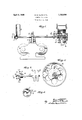
Fig. 1 is a view in part sectional elevation of one embodiment of the invention in which movement in two directions is permitted of the typewheels relative to the typeshaft;
Fig. 2 is a section on the line 22 of Fig. 1;
Fig. 3 is an elevational view of another embodiment of our invention; and
Fig. 4 is a section on the line H of Fig. 3.
Referring first of all to Figures 1 and 2, 3 designates the typeshaft of a conventional stock ticker or printing telegraph mounted in suitable bearings 4 and 5, and driven through a gear train from a spring (not shown) enclosed in a spring barrel or housing 6.
Rotation of the typeshaft is controlled by electrically operated escapement mechanism comprising scape wheel 7 fast upon the shaft 3 and pawls 8.
(One pawl only has been shown.) I
t he apparatus thus far described is con} ventional design and familiar to those skilled in this art.
Heretofore the two typewheels 9 and 10 have been fixedly secured to the typeshaft.
By the present invention, however, we have improved prior constructions by providing for slight relative movement between the wheels and typeshaft.v In the construction illustrated in Figs. 1 and 2 we mount a. sleeve 11 loosely upon the typeshaft, end'motion of the sleeve being prevented by suitable means. Rigidly mounted upon the sleeve 11 are the typewheels 9 and 10 above v referred to. Intermediate the typewheels the sleeve is provided with an oflfset, which may take the form of an annular flange or fin 12. To this flange is secured one end of spring or yielding means 13, the other end of this spring being rigidly attachedto an arm or other suitabledevice 14 clamped fixedly to the typeshaft.
By the above construction, therefore, we provide for slight movementin two directions of the typewheels 9 and 10 relatively to the typeshaft 3, the drive for the typewheels being through the yielding means 13.
' It will be evident with this construction that shocks and jars incident to the intermittent operation of the escapement mechanism will be cushioned by the driving connection 13, and the flywheel action of the typewheels neutralized. I
In the embodiment-of our invention as illustrated in Figs. 3 and 4," the male element 16 of a dog clutch is rigidly secured to the typeshaft, this clutch element having slight play relative to and cooperating with the female element 17 of the clutch as indicated at 18. This member 17 is carried by the scape wheel 7. The scape wheel is frictionally held to the portion 19 of thetypeshaft by a spring 20-coiled about the same, one end of this spring extending outwardly toward the pe ripheryof the scape wheel where it engages a pin 21.
Obviously by this arrangement the scape wheel is yieldingly driven from the typeshaft through the spring 20, so that abrupt stop I d February, 1928.
ping of the scape wheel will be cushioned by the spring. It will be apparent also that the flywheel action of the typewheels 9 and 10 will be neutralized by the slight play permitted between the clutch members 16 and 17.
In both forms of our invention, therefore,
the typewheels are driven through a yielding drive connection to the typeshaft, the drive connection of Figs. 1 and Q-permitting of movement of the typewheels relatively to the typeshaft in two directions, While in Figs. 3 and 4 this movement is in one direction.
What we claim is I 1. In printing telegra phs, the combination of a typewheel, an intermittently rotated shaft,. a spring for rotating said shaft, a scape wheel yieldingly mounted on said shaft, a
second shaft having movement relatively to the first mentioned shaft and carrying said typewheel, and a coupling for coupling the scape wheel to the last mentioned-shaft, and constructed for relatively rotary movement on one direction of rotation. p
2. In printing 'telegraphs, thecombination ,of a typewheel, a shaft carrying the same, a
second shaft, a spring for driving the same, a scape wheel loosely mounted on the last mentioned shaft, a spring for driving said last mentioned shaft, a spring for connecting the scape wheel to its shaft, and a lost motion coupling for coupling-the two shafts to each other. I
3. In printing telegraphs, the combination I of a typewheel, a shaft carrying the same,
a second shaft, a spring for driving the same,
a scape wheel loosely mounted on the last mentioned shaft, a spring for driving the lastmentioned shaft. a spring coiled about thelast mentioned shaft and frictionally held thereto andhaving one end in engagement with the scape wheel yieldingly to connect the scape wheel to the shaft, and a coupling comprising two'members having slight relative rotar movement for cou lin the-sea e v wheel to the first mentioned shaft, one coupling member being carried by the shaft, the other by the scape wheel.
This specification signed this v29 day of GEORGE S. HILTZ. This specification signed this'29 day of February, 1928.
WILLIAM F. PURCELL.
Priority Applications (1)
| Application Number | Priority Date | Filing Date | Title |
|---|---|---|---|
| US258158A US1753656A (en) | 1928-03-01 | 1928-03-01 | Printing telegraph |
Applications Claiming Priority (1)
| Application Number | Priority Date | Filing Date | Title |
|---|---|---|---|
| US258158A US1753656A (en) | 1928-03-01 | 1928-03-01 | Printing telegraph |
Publications (1)
| Publication Number | Publication Date |
|---|---|
| US1753656A true US1753656A (en) | 1930-04-08 |
Family
ID=22979334
Family Applications (1)
| Application Number | Title | Priority Date | Filing Date |
|---|---|---|---|
| US258158A Expired - Lifetime US1753656A (en) | 1928-03-01 | 1928-03-01 | Printing telegraph |
Country Status (1)
| Country | Link |
|---|---|
| US (1) | US1753656A (en) |
-
1928
- 1928-03-01 US US258158A patent/US1753656A/en not_active Expired - Lifetime
Similar Documents
| Publication | Publication Date | Title |
|---|---|---|
| TWI647470B (en) | Light device | |
| US1753656A (en) | Printing telegraph | |
| TW201632060A (en) | Dual-bearing reel | |
| US2484321A (en) | Pump coupling | |
| AU2017271569A1 (en) | Driving force reception assembly and processing box using assembly | |
| US2893221A (en) | Snap-on coupling for a flexible shaft | |
| US1548629A (en) | Cushion coupling | |
| US1639644A (en) | Flexible coupling for shafts | |
| US970793A (en) | Shaft-coupling. | |
| US1008379A (en) | Shock-absorbing coupling. | |
| US2147141A (en) | Mechanical coupling | |
| US2444148A (en) | Coupling device | |
| US976232A (en) | Elastic shaft connection. | |
| US2075078A (en) | Driving mechanism | |
| US2934188A (en) | Irreversible drive | |
| US1707309A (en) | Resilient coupling | |
| US1508879A (en) | Variable velocity-ratio gearing | |
| US3024627A (en) | Flexible coupler | |
| US3286550A (en) | Hypocyclic speed reducers | |
| CN104049484B (en) | Driving component for photosensitive element, handle box and handle box install detection method | |
| US1519959A (en) | Impulse coupling | |
| US981869A (en) | Shock-absorbing pulley. | |
| CN209980019U (en) | Power transmission device and developing cartridge | |
| US1890332A (en) | Flexible elastic coupling | |
| US3602426A (en) | Number wheel for counter or the like |