US1753618A - Frost shield - Google Patents
Frost shield Download PDFInfo
- Publication number
- US1753618A US1753618A US260417A US26041728A US1753618A US 1753618 A US1753618 A US 1753618A US 260417 A US260417 A US 260417A US 26041728 A US26041728 A US 26041728A US 1753618 A US1753618 A US 1753618A
- Authority
- US
- United States
- Prior art keywords
- edge
- suction cups
- shield
- contact
- strip
- Prior art date
- Legal status (The legal status is an assumption and is not a legal conclusion. Google has not performed a legal analysis and makes no representation as to the accuracy of the status listed.)
- Expired - Lifetime
Links
Images
Classifications
-
- B—PERFORMING OPERATIONS; TRANSPORTING
- B60—VEHICLES IN GENERAL
- B60J—WINDOWS, WINDSCREENS, NON-FIXED ROOFS, DOORS, OR SIMILAR DEVICES FOR VEHICLES; REMOVABLE EXTERNAL PROTECTIVE COVERINGS SPECIALLY ADAPTED FOR VEHICLES
- B60J1/00—Windows; Windscreens; Accessories therefor
- B60J1/002—Windows; Windscreens; Accessories therefor with means for clear vision, e.g. anti-frost or defog panes, rain shields
-
- Y—GENERAL TAGGING OF NEW TECHNOLOGICAL DEVELOPMENTS; GENERAL TAGGING OF CROSS-SECTIONAL TECHNOLOGIES SPANNING OVER SEVERAL SECTIONS OF THE IPC; TECHNICAL SUBJECTS COVERED BY FORMER USPC CROSS-REFERENCE ART COLLECTIONS [XRACs] AND DIGESTS
- Y10—TECHNICAL SUBJECTS COVERED BY FORMER USPC
- Y10S—TECHNICAL SUBJECTS COVERED BY FORMER USPC CROSS-REFERENCE ART COLLECTIONS [XRACs] AND DIGESTS
- Y10S160/00—Flexible or portable closure, partition, or panel
- Y10S160/13—Suction cup
Definitions
- My invention relates to frost shields and has for its object to provide a. transparent member with a frame portion integrally connected to said member.
- Another object of the invention resides in forming said frame with an offset portion having a plane surface substantially parallel to the body of said transparent member andwith an outwardly flaring portion connected to said oflset portion and in permanently attaching'to said outwardly flaring portion a. flexible contact strip adapted I to yieldably and freely contact with the surface on which the frost shield is to be applied.
- Another object of the invention resides in depressing the corners of the transparent member to the level of the offset planiform portion and of-attaching suction cups to the corners of said member.
- said suction cups be ing disposed within the outwardly flaring portion of said frame and having the surface thereof disposed substantially in continuity withthe edge of said outwardly flaring portion.
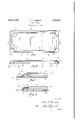
- Fig. 1 is a rear elevational view of my invention detached from the surface to which it is to be applied.
- a Fig. 2 is a. longitudinal sectional view taken on line 22 of Fig. 1.
- Fig. 3 is an enlarged fragmentary sectional view taken on line 3-3 of Fig.1, showing the frost shield attached to the surface of a pane of'glass.
- Fig. 4 is a view similar to Fig. 3 taken on line 44 of Fig. 1.
- the invention proper which is best shown in Figs. land 2, comprises a sheet of celluloid 10 which isarranged with a body portion 11 of proper size and shape and which forms the window through which vision is had.
- the por-. tion 11 as being substantially rectangular in form though it can readily be comprehended thatany size or shape'of'the device may be employed.
- the frame of the device which is indicated in its entirety at 19 is" formed by subjecting the celluloid to pressure in suitable dies under heat. Along the marginal portion of the sheet 10 the same is pressed to provide an offset planiform strip or portion j s 12 which is parallel to the body portion 11
- the full objects and advantagesof my invention will appear in the detailed descripand extends completely around the same.
- the extreme marginal portion of the sheet lO is pressed to form an outwardly flaring portion 14 which extends away from the body portion' 11 and forms a space bej tween the extreme edge 15 of the device of the body portion proper.
- the body portion 11' serves'as a storm window orauxiliary transparent member through which clear vision may be, had while the planiform portion 12 and the outwardly flaring portion 14 form a frame structure integrally connected with the planiform portion 11 and completely surrounding-the same which I previously stated is designated in its entirety at 19.
- the openings 18 are so disposed and the corners of the outwardly flaring portion 19 fsheet -10-is'soconst-ruct ed that the same contacts with thesurfaceofl.
- suction' cups 1 may i :be r arranged: intermediate "those 1dis-.- -s posed: at the corners of.-.the:device: orth'eien the surface-.of-the(glass? on which. it is'to' be chanfra-me 19 imay be slightlycbowedrwtoward a used; *nearithe: center sof the;;sa-Ine;oso:1that when pressure is applied: to. the: various ;suc-.---
- olear'vision throngh theWi-nd shield or-. other -i glass? -;closurres-aof automobiles or Git-.otherastrhqtures.
- berlradqegazrdless of surface on whichthecdevice is attached IJemploy a. contact. strip: 20 which may 2 be con-.. taistructed of. thin-flexibleirubben or. any other suitable material.
- This. contact strip isi ce-1 surface 'of the outwardly: flaring portion: 14
- the contact strip serves to form an effective seal between the transparent member. and the surface of the glass .luponwhich itais to-be-used so that a perfect dead air space is provided.
- the sealing strip may be conveniently spliced at the suction cups so as to avoid a break in the continuity ofthe contacting edge of said contact strip, thereby insuring perfect contact uthroughoutv'the entire.
- Afrost shield comprising a transparent celluloid -memberhaving the -marginalvportions thereof bent out of 'the plane' o-f*1the body of-said member to' form 'a frame: integral therewith, the edge" of said member extenoling obliquely outwardly from said framef-and a flexible contact 7 strip attached to said ob- 'lique edge and extending-in "the same' direction as said edge.
- Aifrost shield comprising a transparent member,aframe surrounding said transpare'nt member, suction? cupsformed with f flar- "ing walls "arranged along 'thet edge of” said frame, and a resilient contact strip attached jointly to said frame afndtothe flaring'walls of said suction cups,.saidfcontact.strip serving to form a dead air space betweerfthetransparent member and the'surface'to which it is attached.
- a frost shield comprising. a transparent member, a frame surrounding said transparent .member-,; said frame .having. an outwardlyflaringledge, suction cups attached to said frame and having flaring ivall s'ldisposed in continuity with. said flaring ⁇ edge and a flexible contact strip. j ointly. attachedto. said .outwardly.flaringuedgeiof saidnframa and to theflaring walls of said suction cups.
- A1 frost-shield comprising a itransparent celluloid member ofasubstantially; rectangular formehavingrthemarginal portion thereof bent out of the planeiofisaidimember to form afra neiintegral with saidememberiand having a planiforlntportion tand can outwardly flaring portion issuing from said planiform portion, the corners of said celluloid member being depressed to the level of said planiform portion, suction cups attached to said celluloid member at said depressed corners and disposed within said frame with the outwardly flaring portion in continuity with the edge of said suction cups, and a flexible contact strip jointly secured to said flaring portion and to the edges of said suction cups.
- a frost shield comprising a transparent celluloid member of substantially rectangular form having the marginal portion thereof bent out of the plane of said member to form a frame integral'with said member and having an oflset planiform' portion and an outwardly flaring portion issuing from said planiform portion, the corners of said celluloid member being depressed to thelevel of said plane surface, suction cups attached to said celluloid member at said depressed corners and disposed within said frame with the outwardly flaring portion in continuity with the edge of said suction cups and a' flexible sealing strip jointly secured to said flaring portion and to the edges of said suction cups, the extreme edge of said flexible contact strip coinciding with the edge of said suction cups and extending outwardly beyond the edge of said outwardly flaring portion.
- a frost shield comprising a transparent celluloid member having a marginal portion thereof bent outwardly therefrom in flaring relation, an elastic contact strip permanently secured to said flaring marginal portion and adapted to yieldably and freely contact along an edge thereof with the surface of the member on which the frost shield is to be applied,
- a frost shield comprising a transparent EMIL T. NORBECK. 5,,
- a frost shield comprising a transparent member, a frame on said member,suction cups attached to said frame, and a flexible contact strip attached to said frame and to said suction cups, said contact strip being joined at its point of attachment to one of said suction cups.
- a frost shield comprising a transparent member, suction cups attached to said member, a contact strip cemented to said member and to one of said suction cups, said contact
Description
April 8, 1930.
E. T. NORBECK FROST SHIELD Filed March 9, 1928 EMU T. Nor bck Patented Apr. 8, 1930 UNITED STATES A EMIL NORBECK, OF MINNEAPOLIS, MINNESOTA FROST SHIELD Application filed March 9,
My invention relates to frost shields and has for its object to provide a. transparent member with a frame portion integrally connected to said member.
Another object of the invention resides in forming said frame with an offset portion having a plane surface substantially parallel to the body of said transparent member andwith an outwardly flaring portion connected to said oflset portion and in permanently attaching'to said outwardly flaring portion a. flexible contact strip adapted I to yieldably and freely contact with the surface on which the frost shield is to be applied.
Another object of the invention resides in depressing the corners of the transparent member to the level of the offset planiform portion and of-attaching suction cups to the corners of said member. said suction cups be ing disposed within the outwardly flaring portion of said frame and having the surface thereof disposed substantially in continuity withthe edge of said outwardly flaring portion.
attaching said contact strip jointly to said outwardly flaring portion and to said suction cups, the edge of said contact strip coinciding with the edge of said suction cups and extending outwardly beyond the edge of said contact strip.
tion thereof and are in the claims. V
In the drawing illustrating my invention in one form:
Fig. 1 is a rear elevational view of my invention detached from the surface to which it is to be applied. a Fig. 2 is a. longitudinal sectional view taken on line 22 of Fig. 1.
Fig. 3 is an enlarged fragmentary sectional view taken on line 3-3 of Fig.1, showing the frost shield attached to the surface of a pane of'glass.
Fig. 4 is a view similar to Fig. 3 taken on line 44 of Fig. 1.
In the use of the frost shield, for automobile wind shields it is desirable to have a particularly pointed out Another object of the invention resides in 1923. Serial No. 260,417.
relatively light construction which will not readily shake loose when applied'to the wind shield and which will form a continuous contact through its extent so as to provide a perfect dead air space and prevent the frosting of the Wind shield when the temperature becomes suflicientlylowered. It is further desirable to construct the frostshield in such a manner that the same is notr'eadilybroken and in the event that the device isroughly handled so that the same will not become permanently injured. 'My invention provides a structure whereby all of these benefits are secured as will become apparent from the following description: p
The invention proper, which is best shown in Figs. land 2, comprises a sheet of celluloid 10 which isarranged with a body portion 11 of proper size and shape and which forms the window through which vision is had. In the instantcase I have illustrated the por-. tion 11 as being substantially rectangular in form though it can readily be comprehended thatany size or shape'of'the device may be employed. The frame of the device which is indicated in its entirety at 19 is" formed by subjecting the celluloid to pressure in suitable dies under heat. Along the marginal portion of the sheet 10 the same is pressed to provide an offset planiform strip or portion j s 12 which is parallel to the body portion 11 The full objects and advantagesof my invention will appear in the detailed descripand extends completely around the same. In additionthe extreme marginal portion of the sheet lOis pressed to form an outwardly flaring portion 14 which extends away from the body portion' 11 and forms a space bej tween the extreme edge 15 of the device of the body portion proper. When applied to a wind shieldor other window on which the device is to be used the body portion 11' serves'as a storm window orauxiliary transparent member through which clear vision may be, had while the planiform portion 12 and the outwardly flaring portion 14 form a frame structure integrally connected with the planiform portion 11 and completely surrounding-the same which I previously stated is designated in its entirety at 19.
At the four corners'of the body portion 11 indicated at 16 the body of said frost shield cupsso that the same maybedisposed .Witl1- in the frame structure 19. previously'referred;
to. It will be noted that the openings 18 are so disposed and the corners of the outwardly flaring portion 19 fsheet -10-is'soconst-ruct ed that the same contacts with thesurfaceofl. the suction cups 17, causing the stirfacebfsaid suction cups at their contacting-(portions with the members 14;, to lie in substani tiall continuity; ttherewith.
For thewpurposeof! effecting a tightvclo- --.;.sure so as tocprovide aiperfect -dead' airrspace "1 between theratranspanent membercl]; ian'dcthe mented or otherwise attached; toa .the 1 outer and to the contactingisurfaces of the various Y cups\l7.;-'- It will be.notednthatiitheaextreme outer edge 21Zofthis contactstrip coincides with; the .z-corresp'onding :edge 22; of: the =va- 1 outwardly beyond :the outer .:eclge.23 of the outwardly. flaring portion .14:- of: the device proper. Due toithis --construction: the con-.
:the seal. .a-longL-the surface of the J glass? and when the suction cupssarerpressed in :place t'he'sa1d contact SiZIlPifOIIIIS amontinuaous contact throughout its extentawithi the surfaceof the glass'to which it: is att'ached -so.that a perfect-=:dead air. space: isprovided.
E Inthe. use of the: invention'itris'i merely ;necessary tomoisten the suction- 1cups=or, if
desired, to: apply any 1 other suitable liquid. thereto and to merely:- press: the device inplace :upon. the wind: shield. I The tsuction t. cups 17 hold the structurerproperly.attached While the extreme edge 2L of thelconta ct strip A '20 =formszcontinuous. contact with :the; surface of the windshield upon whicht-h'e device is attached. 1 WVhere; the length -;of 'cthe sfrost shield. is fairly great additional suction' cups 1; may i :be r arranged: intermediate "those 1dis-.- -s posed: at the corners of.-.the:device: orth'eien the surface-.of-the(glass? on which. it is'to' be tirerfra-me 19 imay be slightlycbowedrwtoward a used; *nearithe: center sof the;;sa-Ine;oso:1that when pressure is applied: to. the: various ;suc-.---
tionclips 17-; contact rmay beheld-throughout 00. I the extentiof the-sealing strip. 20.,
My-zinventions is highlymadvantageous in athat a simple .andreffecti've device is provided:
whereby olear'vision throngh :theWi-nd shield or-. other -i glass? -;closurres-aof automobiles or Git-.otherastrhqtures. may: berlradqegazrdless of surface on whichthecdevice is attached IJemploy a. contact. strip: 20 which may 2 be con-.. taistructed of. thin-flexibleirubben or. any other suitable material. This. contact strip; isi ce-1 surface 'of the outwardly: flaring portion: 14
rious suction cups 17' whileithe.same.=extends tact stripz'QO may *be 'conveniently sp'liced at any-"of :the suction :cups :withoutwbreakingi in constant motion. The contact strip serves to form an effective seal between the transparent member. and the surface of the glass .luponwhich itais to-be-used so that a perfect dead air space is provided. By attaching the contact strip'jointly to the marginal edge of the framestructure and suction cups the sealing strip may be conveniently spliced at the suction cups so as to avoid a break in the continuity ofthe contacting edge of said contact strip, thereby insuring perfect contact uthroughoutv'the entire. marginal portion of :Jthe. device: Theframe of the device being inc tegrally connectedrwiththetransparentwmember forms a rigid constructionwhichwmay be bent: or :otherwise distorted without becomeing permanently inj ur.ed,- rendering the device particularly applicable for. use on motorzvehicles. Changes in the'specifio formz of myiinventionyas herein 'disclosed,:magy beamadewithin the scope of what isfcla'imed withoutdepartin'g from the spirits of miy invention.
i Having describediimyoinventionyvitwhat I claim as new and ides-ire; tobpr'otectibynlietters Patent is:
y 1-: Afrost shield comprising a transparent celluloid -memberhaving the -marginalvportions thereof bent out of 'the plane' o-f*1the body of-said member to' form 'a frame: integral therewith, the edge" of said member extenoling obliquely outwardly from said framef-and a flexible contact 7 strip attached to said ob- 'lique edge and extending-in "the same' direction as said edge. e
v 2. Aifrost shield comprising a transparent member,aframe surrounding said transpare'nt member, suction? cupsformed with f flar- "ing walls "arranged along 'thet edge of" said frame, and a resilient contact strip attached jointly to said frame afndtothe flaring'walls of said suction cups,.saidfcontact.strip serving to form a dead air space betweerfthetransparent member and the'surface'to which it is attached. I I p 2 I 3.. A frost shield comprising. a transparent member, a frame surrounding said transparent .member-,; said frame .having. an outwardlyflaringledge, suction cups attached to said frame and having flaring ivall s'ldisposed in continuity with. said flaring {edge and a flexible contact strip. j ointly. attachedto. said .outwardly.flaringuedgeiof saidnframa and to theflaring walls of said suction cups.
4.1 A1 frost-shield comprising a itransparent celluloid member ofasubstantially; rectangular formehavingrthemarginal portion thereof bent out of the planeiofisaidimember to form afra neiintegral with saidememberiand having a planiforlntportion tand can outwardly flaring portion issuing from said planiform portion, the corners of said celluloid member being depressed to the level of said planiform portion, suction cups attached to said celluloid member at said depressed corners and disposed within said frame with the outwardly flaring portion in continuity with the edge of said suction cups, and a flexible contact strip jointly secured to said flaring portion and to the edges of said suction cups.
5. A frost shield comprising a transparent celluloid member of substantially rectangular form having the marginal portion thereof bent out of the plane of said member to form a frame integral'with said member and having an oflset planiform' portion and an outwardly flaring portion issuing from said planiform portion, the corners of said celluloid member being depressed to thelevel of said plane surface, suction cups attached to said celluloid member at said depressed corners and disposed within said frame with the outwardly flaring portion in continuity with the edge of said suction cups and a' flexible sealing strip jointly secured to said flaring portion and to the edges of said suction cups, the extreme edge of said flexible contact strip coinciding with the edge of said suction cups and extending outwardly beyond the edge of said outwardly flaring portion.
6. A frost shield comprising a transparent celluloid member having a marginal portion thereof bent outwardly therefrom in flaring relation, an elastic contact strip permanently secured to said flaring marginal portion and adapted to yieldably and freely contact along an edge thereof with the surface of the member on which the frost shield is to be applied,
and means for detachably securing said transparent member to the surface on which it is applied with said contact strip in contact therewith.
7. A frost shield comprising a transparent EMIL T. NORBECK. 5,,
celluloid member having a marginal portion a thereof bent out of the plane of said member to form an offset planifrom strip parallel to said transparent member, and the extreme edge thereof bent outwardly from said planiform strip in oblique relation thereto, and a flexible contact strip secured to said oblique edge, and means for attachingthe frost shield to a window with the edge of said contact atrip in contact with the surface of the win- 8. A frost shield comprising a transparent member, a frame on said member,suction cups attached to said frame, and a flexible contact strip attached to said frame and to said suction cups, said contact strip being joined at its point of attachment to one of said suction cups.
9. A frost shield comprising a transparent member, suction cups attached to said member, a contact strip cemented to said member and to one of said suction cups, said contact
Priority Applications (1)
| Application Number | Priority Date | Filing Date | Title |
|---|---|---|---|
| US260417A US1753618A (en) | 1928-03-09 | 1928-03-09 | Frost shield |
Applications Claiming Priority (1)
| Application Number | Priority Date | Filing Date | Title |
|---|---|---|---|
| US260417A US1753618A (en) | 1928-03-09 | 1928-03-09 | Frost shield |
Publications (1)
| Publication Number | Publication Date |
|---|---|
| US1753618A true US1753618A (en) | 1930-04-08 |
Family
ID=22989072
Family Applications (1)
| Application Number | Title | Priority Date | Filing Date |
|---|---|---|---|
| US260417A Expired - Lifetime US1753618A (en) | 1928-03-09 | 1928-03-09 | Frost shield |
Country Status (1)
| Country | Link |
|---|---|
| US (1) | US1753618A (en) |
Cited By (9)
| Publication number | Priority date | Publication date | Assignee | Title |
|---|---|---|---|---|
| US20140331578A1 (en) * | 2013-01-07 | 2014-11-13 | WexEnergy LLC | Supplemental window for fenestration |
| US20150068140A1 (en) * | 2013-01-07 | 2015-03-12 | WexEnergy LLC | Frameless Supplemental Window for Fenestration |
| US20150184444A1 (en) * | 2013-01-07 | 2015-07-02 | WexEnergy LLC | Frameless Supplemental Window For Fenestration Incorporating Infiltration Blockers |
| US10196850B2 (en) | 2013-01-07 | 2019-02-05 | WexEnergy LLC | Frameless supplemental window for fenestration |
| US10280679B2 (en) | 2017-04-12 | 2019-05-07 | Inovues, Inc. | System for retrofitting glazing systems of buildings |
| US10346999B2 (en) | 2013-01-07 | 2019-07-09 | Wexenergy Innovations Llc | System and method of measuring distances related to an object utilizing ancillary objects |
| US10533364B2 (en) | 2017-05-30 | 2020-01-14 | WexEnergy LLC | Frameless supplemental window for fenestration |
| US20210102422A1 (en) * | 2013-01-07 | 2021-04-08 | WexEnergy LLC | Frameless supplemental window for fenestration |
| US11970900B2 (en) * | 2020-12-16 | 2024-04-30 | WexEnergy LLC | Frameless supplemental window for fenestration |
-
1928
- 1928-03-09 US US260417A patent/US1753618A/en not_active Expired - Lifetime
Cited By (16)
| Publication number | Priority date | Publication date | Assignee | Title |
|---|---|---|---|---|
| US20210102422A1 (en) * | 2013-01-07 | 2021-04-08 | WexEnergy LLC | Frameless supplemental window for fenestration |
| US20150068140A1 (en) * | 2013-01-07 | 2015-03-12 | WexEnergy LLC | Frameless Supplemental Window for Fenestration |
| US20150184444A1 (en) * | 2013-01-07 | 2015-07-02 | WexEnergy LLC | Frameless Supplemental Window For Fenestration Incorporating Infiltration Blockers |
| US9234381B2 (en) * | 2013-01-07 | 2016-01-12 | WexEnergy LLC | Supplemental window for fenestration |
| US9663983B2 (en) * | 2013-01-07 | 2017-05-30 | WexEnergy LLC | Frameless supplemental window for fenestration incorporating infiltration blockers |
| US9845636B2 (en) * | 2013-01-07 | 2017-12-19 | WexEnergy LLC | Frameless supplemental window for fenestration |
| US20180106096A1 (en) * | 2013-01-07 | 2018-04-19 | WexEnergy LLC | Frameless supplemental window for fenestration |
| US10196850B2 (en) | 2013-01-07 | 2019-02-05 | WexEnergy LLC | Frameless supplemental window for fenestration |
| US20140331578A1 (en) * | 2013-01-07 | 2014-11-13 | WexEnergy LLC | Supplemental window for fenestration |
| US10346999B2 (en) | 2013-01-07 | 2019-07-09 | Wexenergy Innovations Llc | System and method of measuring distances related to an object utilizing ancillary objects |
| US10501981B2 (en) * | 2013-01-07 | 2019-12-10 | WexEnergy LLC | Frameless supplemental window for fenestration |
| US10280679B2 (en) | 2017-04-12 | 2019-05-07 | Inovues, Inc. | System for retrofitting glazing systems of buildings |
| US10801254B2 (en) | 2017-04-12 | 2020-10-13 | Inovues, Inc. | System for retrofitting glazing systems of buildings |
| US11905753B2 (en) | 2017-04-12 | 2024-02-20 | Inovues, Inc. | System for retrofitting glazing systems of buildings |
| US10533364B2 (en) | 2017-05-30 | 2020-01-14 | WexEnergy LLC | Frameless supplemental window for fenestration |
| US11970900B2 (en) * | 2020-12-16 | 2024-04-30 | WexEnergy LLC | Frameless supplemental window for fenestration |
Similar Documents
| Publication | Publication Date | Title |
|---|---|---|
| US1753618A (en) | Frost shield | |
| US1975895A (en) | Sealed double-pane glass and frame | |
| US3514916A (en) | Sealing strip | |
| US1694677A (en) | Antifrosting device for windows | |
| US1448508A (en) | Windshield cleaner | |
| US2468439A (en) | Automobile ventilating shield | |
| GB399972A (en) | Improvements relating to motor vehicle wind screens | |
| US2139780A (en) | Weather strip | |
| US2664602A (en) | Draught excluding strip | |
| US1119177A (en) | Attachment for wind-shields and the like. | |
| US2061760A (en) | Division molding for a windshield | |
| US2111343A (en) | Connecter strip and frost shield using the same | |
| US1681443A (en) | Antifrost device for windows | |
| US2223459A (en) | Combination thermoplastic window frame and weather seal | |
| USRE17821E (en) | Antifrost device for windows | |
| GB244277A (en) | Improvements in or relating to screens for motor vehicles | |
| US1635906A (en) | Windshield attachment | |
| US1931315A (en) | Strip material and method of making the same | |
| US1545694A (en) | Weather strip | |
| US2837018A (en) | Automobile glass transparency device | |
| US2102597A (en) | Windshield attachment | |
| US2115036A (en) | Ventilating device for automobiles | |
| US1855588A (en) | Adjustable visor | |
| US1824751A (en) | Antifrost shield | |
| US1917799A (en) | Antiglare device |