US1753611A - Tray - Google Patents
Tray Download PDFInfo
- Publication number
- US1753611A US1753611A US299864A US29986428A US1753611A US 1753611 A US1753611 A US 1753611A US 299864 A US299864 A US 299864A US 29986428 A US29986428 A US 29986428A US 1753611 A US1753611 A US 1753611A
- Authority
- US
- United States
- Prior art keywords
- holder
- receptacle
- rubber
- indicated
- tray
- Prior art date
- Legal status (The legal status is an assumption and is not a legal conclusion. Google has not performed a legal analysis and makes no representation as to the accuracy of the status listed.)
- Expired - Lifetime
Links
Images
Classifications
-
- B—PERFORMING OPERATIONS; TRANSPORTING
- B43—WRITING OR DRAWING IMPLEMENTS; BUREAU ACCESSORIES
- B43M—BUREAU ACCESSORIES NOT OTHERWISE PROVIDED FOR
- B43M99/00—Subject matter not provided for in other groups of this subclass
- B43M99/008—Desk-receptacles for holding writing appliances
Definitions
- the present invention relates to devices adapted to be placed on a desk and contain pins, clips or other small articles and has for its object to produce a device. of this kind that will be free from the objections inherlent in ordinary trays or receptacles intended for this purpose.
- present invention may be said to have for its object to produce a simple and novel 4tray of glass or other fragile material so enclosed in a 30 rubber sheathing thatit willl be protected against brealn'ng.
- the lower portion of the rubber holder is preferably made comparatively thick at the sides, while the bottom face is dished.
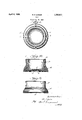
- the present invention may be said to havev for its object to produce a simple and novel tray or the like that may be firmly attached to a smooth sup- Figure lis a top plan view of the device arranged in accordance with my invention;
- Fig. 2 is a central vertical section through the device in its normal condition; and
- 1 represents a receptacle of lass -or other suitable hard mater1al,'in the orm of a cup or bowl.
- the member l is set into a cup-shaped member 2 of flexible rubber, the cavity in which may nor" mally be slightly smaller than the external dimensions of the receptacle, so that when the latter is pressed Ainto the holder it is held firmly gripped in the latter.
- At the top of the holder is an annular, internally-,directed iiange 3 that ⁇ extends across the upper edge of the receptacle.
- the sides of the holder are lpreferably thickened out-,
- the bottom face of the holder is concave, rising gradually from the periphery of the base to the center.
- the central portion of the bottom of the holder is preferably made comparatively thin, as indicated vat 6.
- the bottom face vof the receptacle may be made concave, as indicated at 7, so that ordinarily the receptacle not touch the thin central area of the bottom of the holder, and the latter may stretch freely, 100
- a device of the character described comprising a cup-shaped member of eble 4.o rubber thickened outwardly around the lower end, the bottom face of said member rising gradually from the periphery to the center, and a rigid receptacle fitting into the cavity in said member. 4
Landscapes
- Table Equipment (AREA)
- Packaging Frangible Articles (AREA)
Description
Patented Apr. 1930 UNITED ,STA-Tas mvnil' S. LOWER, 0l' BABBBTON, OHIO, SSIQNOR T0 THE SUN RUBBER OOHPANY,
.A CORPORATION OF OHIO TRAY Application. llled August 15, 1928. Serial No. 299,884.
The present invention relates to devices adapted to be placed on a desk and contain pins, clips or other small articles and has for its object to produce a device. of this kind that will be free from the objections inherlent in ordinary trays or receptacles intended for this purpose.
In carrying out my invention, I employ a cup-shaped receptacle of glass or other stilf material, and set the same in a'holder of flexible rubber flanged at the top to overlie the upperedge of the rece tacle. Consequently,
in the event that the evice is dropped, the
receptacle is protected by the rubber and the danger of breakage is reduced to a minimum.
T erefore, viewed in one of its aspects, the
present invention may be said to have for its object to produce a simple and novel 4tray of glass or other fragile material so enclosed in a 30 rubber sheathing thatit willl be protected against brealn'ng.
The lower portion of the rubber holder is preferably made comparatively thick at the sides, while the bottom face is dished. When the device is pressed rm'ly down against a fiat surface and then the pressure is gradually released, a partial vacuum will be created between the bottom of the device and the supporting surface, so that `the device will remain firmly attached to the support.:
Viewed in one of its aspects, the present invention may be said to havev for its object to produce a simple and novel tray or the like that may be firmly attached to a smooth sup- Figure lis a top plan view of the device arranged in accordance with my invention; Fig. 2 is a central vertical section through the device in its normal condition; and Fig. 3`isy porting surface by merely pressing the samer' against such surface andwithout in any way* flrmly held in place. Because of the downa side elevation of the deviceattached to a supporting surface, the lower portion of the devlce being shown in section.
. Referring to the drawing, 1 represents a receptacle of lass -or other suitable hard mater1al,'in the orm of a cup or bowl. The member lis set into a cup-shaped member 2 of flexible rubber, the cavity in which may nor" mally be slightly smaller than the external dimensions of the receptacle, so that when the latter is pressed Ainto the holder it is held firmly gripped in the latter.
At the top of the holder is an annular, internally-,directed iiange 3 that `extends across the upper edge of the receptacle. The sides of the holder are lpreferably thickened out-,
wardly toward the lower end to form a thick flange-like part 4 toproduce a vbase of much larger diameter than the diameter of the bottom of the receptacle. The bottom face of the holder, as indicated at 5, is concave, rising gradually from the periphery of the base to the center. The central portion of the bottom of the holder is preferably made comparatively thin, as indicated vat 6. A
It will be seen that if the device is set upon a polished table or the like andis pressed down as indicated in. Fig. 3, the central portion of the bottom of the holder will be depressed until the bottom face of the holder is substantially flat; thus driving the air between the supporting surface and the underside of the holder out past the periphery of the holder. Then, when the downward pressure is gradually released2 the holder tends to ,85 resume its normal conditlon, creating a pare tial vacuum between the same Aand the su porting surface, and causing the device to ward pressure ofthe surrounding air, the bottom of the holder maynot return 'to the position indicated in'Fig. 2 while a partial vacuum is being maintained, but may remain more or less ilattened as indicated in' Fig. 3. v The bottom face vof the receptacle may be made concave, as indicated at 7, so that ordinarily the receptacle not touch the thin central area of the bottom of the holder, and the latter may stretch freely, 100
without rubbing against the receptacle, when the device is ressed down to lattenthe bottom of the holder.
It will be seen that if the device is dropped '5 on the Hoor' and happens to strike on the open side, the glass receptaclewill not be damaged because it is cushioned by the overlying lip -or flange on the holder. Of course, if 1t strikes the oor while in any other position, the shock is also borne by the rubber. It will also be seen thatmy improved device has a Wide base so that it will-not tip over even if it is simply set on a table. However, when the device is placed on a table having a polished'surface it can be lixed thereto sov that it will always be in one place. It will also be seen that, by reason of the fact that the surfaces that engage lwith a supporting surface are rubber, there is no danger of marring the surface finish of a table or the like by placing my improved device thereon.
While I have illustrated and described with particularity only a single preferred form of my invention, I do not desire to be limited to the exact structural details thus illustrated and described; but intend to cover all forms and arrangements which come Within the definitions of my invention constituting the appended claims.. I claim 1. A device of the character described, ecm- Erising a cup-shaped member of tiem'blelruber having a thick flange-like part around the exterior of the lower end, the bottom face of said member being concave, and a rigid eceptacle fitting into the cavity in said mem- 2. A device of the character described, comprising a cup-shaped member of eble 4.o rubber thickened outwardly around the lower end, the bottom face of said member rising gradually from the periphery to the center, and a rigid receptacle fitting into the cavity in said member. 4
In testimony whereof, I sign this specification.
MELVIN S. LOWER.
asA
Priority Applications (1)
| Application Number | Priority Date | Filing Date | Title |
|---|---|---|---|
| US299864A US1753611A (en) | 1928-08-15 | 1928-08-15 | Tray |
Applications Claiming Priority (1)
| Application Number | Priority Date | Filing Date | Title |
|---|---|---|---|
| US299864A US1753611A (en) | 1928-08-15 | 1928-08-15 | Tray |
Publications (1)
| Publication Number | Publication Date |
|---|---|
| US1753611A true US1753611A (en) | 1930-04-08 |
Family
ID=23156623
Family Applications (1)
| Application Number | Title | Priority Date | Filing Date |
|---|---|---|---|
| US299864A Expired - Lifetime US1753611A (en) | 1928-08-15 | 1928-08-15 | Tray |
Country Status (1)
| Country | Link |
|---|---|
| US (1) | US1753611A (en) |
Cited By (29)
| Publication number | Priority date | Publication date | Assignee | Title |
|---|---|---|---|---|
| US2531955A (en) * | 1947-09-23 | 1950-11-28 | John R Toney | Egg holder |
| US2565793A (en) * | 1949-07-18 | 1951-08-28 | Ellen E Weismantel | Vacuum holding mat |
| US2574270A (en) * | 1947-12-31 | 1951-11-06 | Christian J Leonard | Holder for waste disposal containers |
| US2733581A (en) * | 1956-02-07 | Baby feeding plate | ||
| US2871615A (en) * | 1957-09-23 | 1959-02-03 | John E Borah | Utility device |
| US2875973A (en) * | 1953-12-04 | 1959-03-03 | Hull Mfg Company | Object supporting means |
| US2933280A (en) * | 1957-07-11 | 1960-04-19 | Florence M Hard | Cup holder |
| US2963256A (en) * | 1957-09-23 | 1960-12-06 | John E Borah | Article retainer |
| US3355046A (en) * | 1966-04-22 | 1967-11-28 | Ross T Jolly | Insulating tumbler |
| US4169907A (en) * | 1974-11-15 | 1979-10-02 | J. J. Barker Company Limited | Simulated ceramic tile |
| US4733807A (en) * | 1982-06-14 | 1988-03-29 | Porter Robert E | Container for medicinals |
| US6596374B1 (en) | 1999-03-26 | 2003-07-22 | 3849953 Canada Inc. | Device for securing objects |
| US20090078712A1 (en) * | 2007-09-22 | 2009-03-26 | Israel Harry Zimmerman | Self-anchoring beverage container with directional release and attachment capability |
| US8757418B2 (en) | 2012-11-01 | 2014-06-24 | Israel Harry Zimmerman | Self-anchoring low-profile container anchor with directional release and attachment capability |
| US9814332B2 (en) | 2015-06-29 | 2017-11-14 | Israel Harry Zimmerman | Anchoring device with directional release and attachment capability and protection against inadvertent release |
| US10098815B2 (en) * | 2016-02-15 | 2018-10-16 | Matthew Zerebny | Bottle support shoe with suction base |
| US20190343070A1 (en) * | 2017-05-15 | 2019-11-14 | Ashish Padia | Immovable pet bowl and a method of fabricating thereof |
| US11065401B2 (en) * | 2018-11-21 | 2021-07-20 | Shl Medical Ag | Stand for medicament delivery device, and system comprising stand and medicament delivery device |
| US11255482B1 (en) | 2020-12-30 | 2022-02-22 | Israel Harry Zimmerman | Quick-release anchoring apparatus with acceleration damping |
| US11415266B2 (en) | 2020-12-30 | 2022-08-16 | Israel Harry Zimmerman | Quick-release anchoring apparatus with self-mounted anchor member |
| US11522988B2 (en) | 2021-04-09 | 2022-12-06 | Mighty Ventures, Inc. | Object holder with quick-release anchoring capability |
| US11525475B2 (en) | 2021-03-03 | 2022-12-13 | Mighty Ventures, Inc. | Object holder with quick-release anchoring capability |
| US11542980B2 (en) | 2020-12-30 | 2023-01-03 | Israel Harry Zimmerman | Universal quick-release anchor member |
| US11988242B2 (en) | 2022-03-25 | 2024-05-21 | Mighty Ventures, Inc. | Valve-actuated suction apparatus |
| US12071973B2 (en) | 2022-01-14 | 2024-08-27 | Harry Zimmerman | Universal quick-release vacuum connector |
| US12078257B2 (en) | 2022-10-03 | 2024-09-03 | Harry Zimmerman | Valve-actuated suction apparatus |
| US12133601B2 (en) | 2021-09-21 | 2024-11-05 | Israel Harry Zimmerman | Quick-release anchoring apparatus with acceleration damping |
| US12352384B2 (en) | 2023-06-14 | 2025-07-08 | Israel Harry Zimmerman | Lockable valve-actuated suction apparatus |
| US12442407B2 (en) | 2024-03-21 | 2025-10-14 | Israel Harry Zimmerman | Quick release suction mounting apparatus with longitudinally stable, laterally compliant suction control valve seat |
-
1928
- 1928-08-15 US US299864A patent/US1753611A/en not_active Expired - Lifetime
Cited By (36)
| Publication number | Priority date | Publication date | Assignee | Title |
|---|---|---|---|---|
| US2733581A (en) * | 1956-02-07 | Baby feeding plate | ||
| US2531955A (en) * | 1947-09-23 | 1950-11-28 | John R Toney | Egg holder |
| US2574270A (en) * | 1947-12-31 | 1951-11-06 | Christian J Leonard | Holder for waste disposal containers |
| US2565793A (en) * | 1949-07-18 | 1951-08-28 | Ellen E Weismantel | Vacuum holding mat |
| US2875973A (en) * | 1953-12-04 | 1959-03-03 | Hull Mfg Company | Object supporting means |
| US2933280A (en) * | 1957-07-11 | 1960-04-19 | Florence M Hard | Cup holder |
| US2871615A (en) * | 1957-09-23 | 1959-02-03 | John E Borah | Utility device |
| US2963256A (en) * | 1957-09-23 | 1960-12-06 | John E Borah | Article retainer |
| US3355046A (en) * | 1966-04-22 | 1967-11-28 | Ross T Jolly | Insulating tumbler |
| US4169907A (en) * | 1974-11-15 | 1979-10-02 | J. J. Barker Company Limited | Simulated ceramic tile |
| US4393108A (en) * | 1974-11-15 | 1983-07-12 | J. J. Barker Company Limited | Simulated ceramic tile |
| US4733807A (en) * | 1982-06-14 | 1988-03-29 | Porter Robert E | Container for medicinals |
| US6596374B1 (en) | 1999-03-26 | 2003-07-22 | 3849953 Canada Inc. | Device for securing objects |
| AU777302B2 (en) * | 1999-03-26 | 2004-10-07 | 3849953 Canada Inc. | A device and means for removably securing objects |
| US20090078712A1 (en) * | 2007-09-22 | 2009-03-26 | Israel Harry Zimmerman | Self-anchoring beverage container with directional release and attachment capability |
| US20100187240A1 (en) * | 2007-09-22 | 2010-07-29 | Israel Harry Zimmerman | Self-anchoring beverage container with directional release and attachment capability |
| US8025169B2 (en) * | 2007-09-22 | 2011-09-27 | Israel Harry Zimmerman | Self-anchoring beverage container with directional release and attachment capability |
| US8028850B2 (en) * | 2007-09-22 | 2011-10-04 | Israel Harry Zimmerman | Self-anchoring beverage container with directional release and attachment capability |
| US8757418B2 (en) | 2012-11-01 | 2014-06-24 | Israel Harry Zimmerman | Self-anchoring low-profile container anchor with directional release and attachment capability |
| US9814332B2 (en) | 2015-06-29 | 2017-11-14 | Israel Harry Zimmerman | Anchoring device with directional release and attachment capability and protection against inadvertent release |
| US10098815B2 (en) * | 2016-02-15 | 2018-10-16 | Matthew Zerebny | Bottle support shoe with suction base |
| US20190343070A1 (en) * | 2017-05-15 | 2019-11-14 | Ashish Padia | Immovable pet bowl and a method of fabricating thereof |
| US11065401B2 (en) * | 2018-11-21 | 2021-07-20 | Shl Medical Ag | Stand for medicament delivery device, and system comprising stand and medicament delivery device |
| US11542980B2 (en) | 2020-12-30 | 2023-01-03 | Israel Harry Zimmerman | Universal quick-release anchor member |
| US11415266B2 (en) | 2020-12-30 | 2022-08-16 | Israel Harry Zimmerman | Quick-release anchoring apparatus with self-mounted anchor member |
| US11255482B1 (en) | 2020-12-30 | 2022-02-22 | Israel Harry Zimmerman | Quick-release anchoring apparatus with acceleration damping |
| US11846389B2 (en) | 2020-12-30 | 2023-12-19 | Israel Harry Zimmerman | Quick-release anchoring apparatus with self-mounted anchor member |
| US12422093B2 (en) | 2020-12-30 | 2025-09-23 | Israel Harry Zimmerman | Quick-release anchoring apparatus with stem-mounted air valve |
| US11525475B2 (en) | 2021-03-03 | 2022-12-13 | Mighty Ventures, Inc. | Object holder with quick-release anchoring capability |
| US11522988B2 (en) | 2021-04-09 | 2022-12-06 | Mighty Ventures, Inc. | Object holder with quick-release anchoring capability |
| US12133601B2 (en) | 2021-09-21 | 2024-11-05 | Israel Harry Zimmerman | Quick-release anchoring apparatus with acceleration damping |
| US12071973B2 (en) | 2022-01-14 | 2024-08-27 | Harry Zimmerman | Universal quick-release vacuum connector |
| US11988242B2 (en) | 2022-03-25 | 2024-05-21 | Mighty Ventures, Inc. | Valve-actuated suction apparatus |
| US12078257B2 (en) | 2022-10-03 | 2024-09-03 | Harry Zimmerman | Valve-actuated suction apparatus |
| US12352384B2 (en) | 2023-06-14 | 2025-07-08 | Israel Harry Zimmerman | Lockable valve-actuated suction apparatus |
| US12442407B2 (en) | 2024-03-21 | 2025-10-14 | Israel Harry Zimmerman | Quick release suction mounting apparatus with longitudinally stable, laterally compliant suction control valve seat |
Similar Documents
| Publication | Publication Date | Title |
|---|---|---|
| US1753611A (en) | Tray | |
| US2623369A (en) | Adherent dish | |
| US2628744A (en) | Liquid soap dispenser | |
| US2740545A (en) | Coaster for drinking glasses and the like | |
| US2295860A (en) | Service tray | |
| US1925540A (en) | Brace or bracket for the support of crockery, glassware, kitchen utensils, and the like | |
| US2784577A (en) | Weighted coaster | |
| US2601279A (en) | Nontoppling base for drinking glasses | |
| US2041563A (en) | Sanitary tumbler cover and coaster | |
| US2302802A (en) | Bowling ball carrier | |
| US1759398A (en) | Egg holder | |
| US2126766A (en) | Flower holder | |
| US2113888A (en) | Coaster, serving as support for glasses, and the like | |
| US1781983A (en) | Dice box | |
| US1925241A (en) | Antidrip coaster | |
| US2351666A (en) | Glass-lifting device | |
| US2315591A (en) | Paper dish and base therefor | |
| US2009360A (en) | Pen stand | |
| US2496157A (en) | Coaster | |
| US1975016A (en) | Sponge cup and applicator | |
| GB1152315A (en) | Baby Food Jar Holder | |
| US1580788A (en) | Ash tray and cigar holder | |
| US2754021A (en) | Container stabilizer | |
| US782710A (en) | Drinking-glass or like tableware. | |
| US2187559A (en) | Container |