US1753610A - Means for annulling the effect of stray fields on radio receiving systems - Google Patents
Means for annulling the effect of stray fields on radio receiving systems Download PDFInfo
- Publication number
- US1753610A US1753610A US666395A US66639523A US1753610A US 1753610 A US1753610 A US 1753610A US 666395 A US666395 A US 666395A US 66639523 A US66639523 A US 66639523A US 1753610 A US1753610 A US 1753610A
- Authority
- US
- United States
- Prior art keywords
- magneto
- winding
- currents
- primary
- magnetic field
- Prior art date
- Legal status (The legal status is an assumption and is not a legal conclusion. Google has not performed a legal analysis and makes no representation as to the accuracy of the status listed.)
- Expired - Lifetime
Links
- 230000000694 effects Effects 0.000 title description 2
- 238000004804 winding Methods 0.000 description 33
- 230000008878 coupling Effects 0.000 description 6
- 238000010168 coupling process Methods 0.000 description 6
- 238000005859 coupling reaction Methods 0.000 description 6
- 230000001939 inductive effect Effects 0.000 description 6
- 238000002485 combustion reaction Methods 0.000 description 5
- 244000045947 parasite Species 0.000 description 4
- 230000003071 parasitic effect Effects 0.000 description 4
- 230000004907 flux Effects 0.000 description 2
- 230000006698 induction Effects 0.000 description 2
- 244000118350 Andrographis paniculata Species 0.000 description 1
- 238000010276 construction Methods 0.000 description 1
- 230000005672 electromagnetic field Effects 0.000 description 1
- 238000004519 manufacturing process Methods 0.000 description 1
- 230000005855 radiation Effects 0.000 description 1
Images
Classifications
-
- H—ELECTRICITY
- H04—ELECTRIC COMMUNICATION TECHNIQUE
- H04B—TRANSMISSION
- H04B15/00—Suppression or limitation of noise or interference
- H04B15/02—Reducing interference from electric apparatus by means located at or near the interfering apparatus
- H04B15/025—Reducing interference from ignition apparatus of fuel engines
Definitions
- the ignition apparatuses for internal combustion engines create variable magnetic or electromagnetic fields which produce parasitic actions in the receiving systems used either in wireless telegraphy or wireless telephony, for radiogoniometry, or for steering movable objects bymeans of cables energized by electric currents.
- the parasites which are due to the said 1gnition apparatuses are of two kinds:
- This invention has'for its object to el1m1- nate these parasites, first by creating in the receiving system electric currents which are of the same intensity as and in exact oppos tion to the parasitic currents induced by the ignition apparatus, and second by creat ng magnetic and electromagnetic fields which are, at every moment and at all points ofthe space, equal to those created by the ignition apparatuses and their external circuits.
- Fig. 1 is a diagrammatic View
- Fig. 2 is a sectional view.
- a small compensating receiver 1 (which is a coil forinstance) is placednear or on the 1gnition apparatus (such for instance as a magneto 8).
- the fixed compensating coil 1 is connected to the primary winding 18 of a variable transformer, the secondary winding 19 of which is connected (in series for instance) with the loop antenna 20 of the electromagnetic waves or magnetic field receiving system, in such a manner that the currents induced in the loop antenna 20 and in thecompensating system 1, 18, 19 by the magneto 8 are in opposition.
- the currents opposed to the currents directly induced in the loop antenna 20 are caused to have the same intensity so that the parasiticaction of the magneto 8 is avoided.
- compensating emitter or emitters are tobeplaced:
- This action is then compensated byi'providing, a counter'emitter, a'loop antenna-22 for instance, fed by the secondaryci'rcuit itself, that is to say an emitter the emission of which isequal but opposite to that ofcthe secondary circuit.
- This loop antenna 22 can be so arranged that its emission annuls'the influence of that of theremainder of the secondary circuit.
- the secondary circuit 23"c0mprising the sparking plug 21 influences,- ateach striking of a spark, the receiving antenna-20, in the circuit of which. is a radio receiving set 16, and telephones 15. If the set 16 is sufficiently near the ignition apparatus 8, it will be necessary, at the same time, to compensate the influence of the circuit 23 on this setas by enclosing it in a Faraday cage.
- the low frequency receptions are influenced not. only by the induced currents due to the production and to the cessation of the variable currents circulatingin thei'secondary circuit, but also:
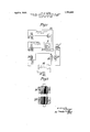
- N designates the north pole of the magnets and S the south pole.
- windings are made separately and in such manner that each particular magnetic field, primary and secondary, of each of them, is equal and of reverse direction, at every moment, to the corresponding particular magnetic field of the other corresponding winding and equal on the other armature.
- These armatures are mounted on the same shaft. They may for instance be controlled by one and the same breaking device or diiferent breaking devices which can be adjustably displaced.
- a magnetic field or electro-magnetic wave receiving system including a loop antenna, an internal combustion engine having a magneto with primary and secondary winding, an emitting winding arranged in series with the primary winding of the magneto to induce in the antenna currents which are equal and in opposition to those induced-by the primary current of the magneto.
- a magnetic field or electromagnetic wave receiving system including a loop antenna, an internal combustion engine having an ignition system including a magneto with primary and secondary circuits creating a magnetic field, and a spark plug, inserted in the secondary circuit of the said magneto, a receiving winding arranged in the magnetic field of the magneto, means for obtaining an inductive coupling between the said winding and the said antenna in such a manner that the currents induced in the winding are in opposition to those induced in the loop antenna, means for modifying the inductive coupling between the winding and the loop antenna, an emitting winding arranged in series in the primary circuit of the magneto, a second emitting winding in series in the secondary circuit of the magneto and with the spark plu 3.
- a magnetic field or electromagnetic wave receiving system including a loop antenna, an internal combustion engine having an ignition system including a magneto with primary and secondary circuits creating a magnetic field, and a spark plug, inserted in the secondary circuit of the said magneto, a receiving winding arranged in the magnetic field of the magneto, means for obtaining an inductive coupling between the said winding and the said antenna in such a manner that the currents induced in the winding are in opposition to those induced in the loop an tenna, means for modifying the inductive coupling between the winding and the loop antenna, an emitting winding arranged in series in the primary circuit of the magneto, a sec- 0nd emitting Winding in series in the secondary circuit of the magneto and with the spark plug, a double pair of inductors for the magneto, the adjacent poles being of opposite polarity, and a corresponding number of armature pairs.
- a magnetic field or electromagnetic Wave receiving system including a loop antenna, an internal combustion engine having an ignition system including a magneto with primary and secondary circuits creating a magnetic field, and a spark plug, inserted in the secondary circuit of the said magneto, a receiving winding arranged in the magnetic field of the magneto, means for obtaining an inductive coupling between the said winding and the said antenna in such a manner that the currents induced in the winding are in opposition to those induced in the loop an" tenna, means for modifying the inductive coupling between the Winding and the loop antenna, an emitting winding arranged in series in the primary circuit or the magneto, a second emitting winding in series in the secondary circuit of the magneto and with the spark plug, a double pair of inductors for the magneto, the adjacent poles being of opposite polarity, a corresponding number of armature pairs, the successive armatures being composed of oppositely wound coils.
- a magnetic field or electromagnetic wave receiving system including a loop antenna, an internal combustion engine having a magneto with primary and secondary winding, an emitting winding arranged in series with the secondary winding of the magneto to induce in the antenna currents which are equal and in opposition to those induced by the secondary current of the magneto.
Landscapes
- Engineering & Computer Science (AREA)
- Computer Networks & Wireless Communication (AREA)
- Signal Processing (AREA)
- Ignition Installations For Internal Combustion Engines (AREA)
Description
April 8, 1930. w A, LOTH 1,753,610
MEANS FOR ANNULLING THE EFFECT OF STRAY FIELDS ON RADIO RECEIVING SYSTEMS Filed Oct. 5, 1925 Primacy circa/if 7". 'mag'nefo INVENTDI" I Patented Apr. 8, 1930 UNITED STATES WILLIAM ARTHUR LOTH, OF PARIS, FRANCE, ASSIGNOR TO SOCIETE INDUSTRIELIJE DES PROCEDES. W. A. LOTH, 0F PARIS, FRANCE MEANS FQRANNULLINGTHE nrrncr or STRAY FIELDS on RADIO nncnrvme SYSTEMS Application filed October 3, 1923, Serial No. 666,395, and in France September 7, 1923.
The ignition apparatuses for internal combustion engines create variable magnetic or electromagnetic fields which produce parasitic actions in the receiving systems used either in wireless telegraphy or wireless telephony, for radiogoniometry, or for steering movable objects bymeans of cables energized by electric currents. V
The parasites which are due to the said 1gnition apparatuses are of two kinds:
Parasites of low and medium frequency (induction) produced by the ignition apparatus itself; even in the absence of sparks and of external ignition circuits.
Parasites of high frequency (radiation) produced by the circuits connecting the ignition apparatus or apparatuses to the sparking plug or plugs.
This invention has'for its object to el1m1- nate these parasites, first by creating in the receiving system electric currents which are of the same intensity as and in exact oppos tion to the parasitic currents induced by the ignition apparatus, and second by creat ng magnetic and electromagnetic fields which are, at every moment and at all points ofthe space, equal to those created by the ignition apparatuses and their external circuits.
In the accompanying drawing and by way of example:
Fig. 1 is a diagrammatic View,
Fig. 2 is a sectional view.
For creating in the receiving system electric currents which are in exact opposition to the parasitic current induced by the magneto, a small compensating receiver 1 (which is a coil forinstance) is placednear or on the 1gnition apparatus (such for instance as a magneto 8). The fixed compensating coil 1 is connected to the primary winding 18 of a variable transformer, the secondary winding 19 of which is connected (in series for instance) with the loop antenna 20 of the electromagnetic waves or magnetic field receiving system, in such a manner that the currents induced in the loop antenna 20 and in thecompensating system 1, 18, 19 by the magneto 8 are in opposition. Owing to the variable connection of the primary winding 18 and secondary winding 19, the currents opposed to the currents directly induced in the loop antenna 20 are caused to have the same intensity so that the parasiticaction of the magneto 8 is avoided.
In order to eliminate the parasitic action of the external circuits of the ignition system use is also made of compensating emitters (coils for instance) which are placed either in the emitting circuits of the ignition apparatuses, or coupled with these circuits, so that the said ignition apparatuses induce currents therein. v
For instance, compensating emitter or emitters are tobeplaced:
(a) In thesecondary circuit (series or parallel), (b) in the primary circuit, (0) in the primary circuit and in the secondary circuit, the sparking plug 21 being fed by the magneto 8, if the spark is struck at a certain distance from the magneto 8,. that is to say if the secondary circuit is extended by one or more wires forming emitters, the influence of the said secondary circuits on the high frequency receivers becomes considerable.
This action is then compensated byi'providing, a counter'emitter, a'loop antenna-22 for instance, fed by the secondaryci'rcuit itself, that is to say an emitter the emission of which isequal but opposite to that ofcthe secondary circuit. This loop antenna 22 can be so arranged that its emission annuls'the influence of that of theremainder of the secondary circuit. In fact the secondary circuit 23"c0mprising the sparking plug 21 influences,- ateach striking of a spark, the receiving antenna-20, in the circuit of which. is a radio receiving set 16, and telephones 15. If the set 16 is sufficiently near the ignition apparatus 8, it will be necessary, at the same time, to compensate the influence of the circuit 23 on this setas by enclosing it in a Faraday cage.
It is moreover advantageous, generally speaking, to place the counter emitter .inthe neighbourhood of the ignition apparatus.
The low frequency receptions are influenced not. only by the induced currents due to the production and to the cessation of the variable currents circulatingin thei'secondary circuit, but also:
(a) By the induced currents due to the variable currents circulating in the primary circuit;
(6) By the currents induced in the receivers due to the variations of the magnetic field of the permanent magnets produced themselves by the variation of the air-gap in the case of magnetos of any types (with movable armatures, shields, etc).
It results therefrom that it is necessary in the case of the low frequency, to compensate not only the emission of the secondary circuit by a counter-emitter as indicated, but also to compensate the emission of the primary circuit. For this latter purpose, another emitter (coil 25) is introduced in the primary circuit, directly, (in series or in parallel or by any other combination) or indirectly (action by induction). A variable low frequency current after passin through this emitter 25 produces a variable magnetic field which is opposed to that due to the primary current.
It is also necessary to produce creating magnetic fields equal and opposed to those generated by the ignition apparatus itself, in order that two fluxes equal and of reverse directions pass at the same time through one or more turns 20; consequently, the resulting current induced in the winding is null and the current detector is not influenced by any current.
For obtaining these equal magnetic fields of reverse direction, use is made, in the case chosen for example, of two permanent magnets 25, 25 giving substantially equal fluxes and they are placed in reverse direction. N designates the north pole of the magnets and S the south pole.
Thus, there is obtained, passing between each magnet an induced winding and a field winding, consequently two groups called: double T movable armatures.
These windings are made separately and in such manner that each particular magnetic field, primary and secondary, of each of them, is equal and of reverse direction, at every moment, to the corresponding particular magnetic field of the other corresponding winding and equal on the other armature. These armatures are mounted on the same shaft. They may for instance be controlled by one and the same breaking device or diiferent breaking devices which can be adjustably displaced.
It is thus possible to create two equal magnetic fields of reverse directions.
In order that their influence annuls itself on receivers, these fields must be very exactly superposed. This result is obtained by causing one of the magnets to be movable about an axis coinciding with that of the rotating armature. A perfect superposition is thus obtained. It may happen-that this adjustment is unnecessary, if the construction has been very carefully effected. This movement is therefore adopted only to correct a want of precision in the assemblage and it allows of taking it up.
Two magnetic fields of reverse directions, equal and exactly superposed to each other are thus obtained. It remains now to produce them at the same moment, since in the case of the magneto under consideration, it is a discontinuous field.
What I claim as my invention and desire to secure by Letters Patent is:
1. In a magnetic field or electro-magnetic wave receiving system including a loop antenna, an internal combustion engine having a magneto with primary and secondary winding, an emitting winding arranged in series with the primary winding of the magneto to induce in the antenna currents which are equal and in opposition to those induced-by the primary current of the magneto.
2. In a magnetic field or electromagnetic wave receiving system including a loop antenna, an internal combustion engine having an ignition system including a magneto with primary and secondary circuits creating a magnetic field, and a spark plug, inserted in the secondary circuit of the said magneto, a receiving winding arranged in the magnetic field of the magneto, means for obtaining an inductive coupling between the said winding and the said antenna in such a manner that the currents induced in the winding are in opposition to those induced in the loop antenna, means for modifying the inductive coupling between the winding and the loop antenna, an emitting winding arranged in series in the primary circuit of the magneto, a second emitting winding in series in the secondary circuit of the magneto and with the spark plu 3. In a magnetic field or electromagnetic wave receiving system including a loop antenna, an internal combustion engine having an ignition system including a magneto with primary and secondary circuits creating a magnetic field, and a spark plug, inserted in the secondary circuit of the said magneto, a receiving winding arranged in the magnetic field of the magneto, means for obtaining an inductive coupling between the said winding and the said antenna in such a manner that the currents induced in the winding are in opposition to those induced in the loop an tenna, means for modifying the inductive coupling between the winding and the loop antenna, an emitting winding arranged in series in the primary circuit of the magneto, a sec- 0nd emitting Winding in series in the secondary circuit of the magneto and with the spark plug, a double pair of inductors for the magneto, the adjacent poles being of opposite polarity, and a corresponding number of armature pairs.
4. In a magnetic field or electromagnetic Wave receiving system including a loop antenna, an internal combustion engine having an ignition system including a magneto with primary and secondary circuits creating a magnetic field, and a spark plug, inserted in the secondary circuit of the said magneto, a receiving winding arranged in the magnetic field of the magneto, means for obtaining an inductive coupling between the said winding and the said antenna in such a manner that the currents induced in the winding are in opposition to those induced in the loop an" tenna, means for modifying the inductive coupling between the Winding and the loop antenna, an emitting winding arranged in series in the primary circuit or the magneto, a second emitting winding in series in the secondary circuit of the magneto and with the spark plug, a double pair of inductors for the magneto, the adjacent poles being of opposite polarity, a corresponding number of armature pairs, the successive armatures being composed of oppositely wound coils.
5. In a magnetic field or electromagnetic wave receiving system including a loop antenna, an internal combustion engine having a magneto with primary and secondary winding, an emitting winding arranged in series with the secondary winding of the magneto to induce in the antenna currents which are equal and in opposition to those induced by the secondary current of the magneto.
In testimony whereof, I have signed my name to this specification.
WILLIAM ARTHUR LOTH.
Applications Claiming Priority (1)
| Application Number | Priority Date | Filing Date | Title |
|---|---|---|---|
| FR1753610X | 1923-09-07 |
Publications (1)
| Publication Number | Publication Date |
|---|---|
| US1753610A true US1753610A (en) | 1930-04-08 |
Family
ID=9680762
Family Applications (2)
| Application Number | Title | Priority Date | Filing Date |
|---|---|---|---|
| US19395D Expired USRE19395E (en) | 1923-09-07 | Means for annulling the effect of | |
| US666395A Expired - Lifetime US1753610A (en) | 1923-09-07 | 1923-10-03 | Means for annulling the effect of stray fields on radio receiving systems |
Family Applications Before (1)
| Application Number | Title | Priority Date | Filing Date |
|---|---|---|---|
| US19395D Expired USRE19395E (en) | 1923-09-07 | Means for annulling the effect of |
Country Status (1)
| Country | Link |
|---|---|
| US (2) | US1753610A (en) |
Cited By (1)
| Publication number | Priority date | Publication date | Assignee | Title |
|---|---|---|---|---|
| US3071752A (en) * | 1958-01-02 | 1963-01-01 | Strasberg Murray | Interference reduction apparatus |
-
0
- US US19395D patent/USRE19395E/en not_active Expired
-
1923
- 1923-10-03 US US666395A patent/US1753610A/en not_active Expired - Lifetime
Cited By (1)
| Publication number | Priority date | Publication date | Assignee | Title |
|---|---|---|---|---|
| US3071752A (en) * | 1958-01-02 | 1963-01-01 | Strasberg Murray | Interference reduction apparatus |
Also Published As
| Publication number | Publication date |
|---|---|
| USRE19395E (en) | 1934-12-11 |
Similar Documents
| Publication | Publication Date | Title |
|---|---|---|
| FI72009B (en) | FOER KATODSTRAOLEROER AVSETT MAGNETISERINGSFOERFARANDE | |
| US2482875A (en) | Magnetogenerator | |
| US4129107A (en) | Magnetic pickup type ignition distributor | |
| FI61581B (en) | ANORDNING FOER OVERFOERING AV INFORMATION GENOM MAGNETIC INDUCTION | |
| SU1271386A3 (en) | Magetizing device for colour purity magnet of colour kinescope with coplanar arrangement of three electron guns | |
| US2817782A (en) | Cathode ray tube deflection apparatus | |
| US1753610A (en) | Means for annulling the effect of stray fields on radio receiving systems | |
| GB747736A (en) | Improvements in or relating to devices comprising a circuit of highly-permeable material and a permanent magnet for producing a pre-magnetizing field in said circuit | |
| US3370190A (en) | Electromagnetic pickup device | |
| US2230878A (en) | Magnetoelectric ignition apparatus | |
| US2695370A (en) | Permanent magnet for dynamoelectric machines | |
| US2710929A (en) | Magneto | |
| US1105924A (en) | Telephone. | |
| US2846606A (en) | Television receiver | |
| US3753429A (en) | Internal combustion engine ignition system | |
| US2485569A (en) | Method of and apparatus for compensating for residual magnetization in cathode-ray apparatus | |
| GB1077412A (en) | Cathode-ray tube beam controlling device | |
| US2164915A (en) | Induction timer | |
| US1935230A (en) | Dynamo-electric machine | |
| US912565A (en) | Dynamo-electric generator. | |
| US3061753A (en) | Indicating system comprising a cathode ray tube | |
| US1743071A (en) | Sound receiver | |
| US1361259A (en) | Startino ast ignition system | |
| US1960919A (en) | Ignition system | |
| US3379923A (en) | Convergence correction |