US1752182A - Current collector for hoisting apparatus - Google Patents
Current collector for hoisting apparatus Download PDFInfo
- Publication number
- US1752182A US1752182A US329040A US32904028A US1752182A US 1752182 A US1752182 A US 1752182A US 329040 A US329040 A US 329040A US 32904028 A US32904028 A US 32904028A US 1752182 A US1752182 A US 1752182A
- Authority
- US
- United States
- Prior art keywords
- current collector
- conductor
- spring
- contact means
- hoisting apparatus
- Prior art date
- Legal status (The legal status is an assumption and is not a legal conclusion. Google has not performed a legal analysis and makes no representation as to the accuracy of the status listed.)
- Expired - Lifetime
Links
Images
Classifications
-
- H—ELECTRICITY
- H01—ELECTRIC ELEMENTS
- H01R—ELECTRICALLY-CONDUCTIVE CONNECTIONS; STRUCTURAL ASSOCIATIONS OF A PLURALITY OF MUTUALLY-INSULATED ELECTRICAL CONNECTING ELEMENTS; COUPLING DEVICES; CURRENT COLLECTORS
- H01R41/00—Non-rotary current collectors for maintaining contact between moving and stationary parts of an electric circuit
Definitions
- My invention relates to current collectors, and it has for one object the provision of a simple, eflicient and compact current collector particularly applicable to hoisting apparatus.
- Another object of my invention is to provide a current collector of minimum weight and maximum strength, wherein the several parts are formed of metal stampings.
- a further object of my invention is to provide a current collect-or having maximum flexibility both vertical as well as lateral, whereby good contact may be automatically maintained with a supply conductor, regardless of irregularities therein.
- a still further object of my invention is to provide a current collector adapted to coact with a conductor, comprising contact means, and means permitting a maximum adjustment in the position of said contact means, so that the proper positioning of said contact means relative to the conductor may be effective at a minimum expenditure of time and effort.
- a still further object of my invention is to provide a current collector for a device, comprising contact means adapted to co-act with a conductor, and means whereby the position of the contact means may be manually adjusted at a plurality of points so as to afford both coarse and fine adjustments.
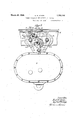
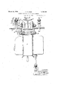
- Fig. 1 is a side elevational View of m invention, showing the application thereo to a hoist;
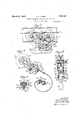
- Fig. 2 is a detail view of the current collec tor illustrated in Fig. 1, but showing the position of the-adjustable parts when the supply conductor is lowered;
- Fig. 3 is an end elevational view, partially in section on the line 33 of Fig. 1;
- Fig. 4 is an enlarged detail side elevational View of the collector wheel and its adjacent supporting parts.
- Figs. 5 and 6 are sectional views taken on the lines 55 and 66 respectively of Fig. 4.
- the hoist therein shown comprises broadly pressed-steel trolley frame 1 carrying pairs of wheels 2 and 3 which are mounted on a track formed by an I-beam 4; a pressed-steel hoist body portion 5 which'is swingingly mounted on the trolley frame 1 by means of a pivot bolt,6; and a pair of pressed-steel current collectors 7'- and 8 for co-action with conductors 9 and 11, respectively, the collectors being adjustably mounted on end portions 12 and 13 of the supporting bolt 6 extending beyond the trolley frame 1.
- the collector 7 broadly comprises contact means 14, wh1ch may take the form of a pressed-steel trolley wheel or shoe having a groove 15 adapted to co-act with the supply conductor 9; a pressed steel yoke or saddle 16 for d rectly supporting the trolley wheel 14; an insulating member 17 for mounting the yoke 16 on an upper free end 18 of a spiral spring 19, formed of a pressed-steel strip and an adjustable pressed or forged steel supporting bracket 21 having an upper horizontal arm portion 22 formed to provide an adjustable mounting for a clamping portion 23 of the spiral spring 4, 5 and 6 are detail views, a main body portion 26 thereof is provided with a bottom wall 27, and side walls 28 and 29 forming a recess adapted to receive a body portion 32 of the insulating block 17.
- the portion 32 may be secured in position by means of a bolt 33 which passes through the wall 27, the body portion 32 and a cap 34 which fits over an outer side 35 of the body portion 32 and overlaps adjacent edge portions of the side walls 28 and 29.
- a projecting end portion, 36 of the bolt 33 is threaded for the reception of a clamping.
- nut 37 A second nut 38 may be mounted on the threaded end portion 36, in order that a conductor may be suitably attached to the live portion of the current collector 7.
- the side walls 28 and 29 of the yoke 16 are provided with outwardly-extending projections 39 and 41, the ends of which are apertured to receive a pin 42 affording the collector wheel 14 a suitable mounting.
- an end portion 43 of a hub 44 of the trolley wheel 14 is resiliently held in abutting engagement with an inner side 45 of the yoke extension 41 by means of a spring 46 which engages an opposite end portion 47 of the hub 44.
- the spring 46' is secured to an inner side of the yoke extension 39.
- the frictional spring 46 serves to ber 17 has imbedded therein a flattened tube 48.
- the tube 48 projects from the members 17 through a recess 49 in an end portion51 thereof and terminates in an end portion 52 which is positioned slightly beyond an edge 53 of the end portion 51.
- the flattened tube 48' forms a recess adapted to rEeive the upperend 18 of the spiral spring 19.
- These parts may be detachably connected together by means of a clamping bolt 54 and a nut 55.- Leakage from the yoke 16 to the spiral spring 19 is prevented by outwardly flaring the end portion 51 of the insulating member 17, as shown in Figs. 4 and 5.
- the spiral spring 19 affords a support for the trolley wheel 14 and the yoke 16 and is effectively insulated therefrom.
- An inner end of the spiral spring 19 is provided with the mounting portion 23 which is formed by bendingthe end of the spring 19 around the horizontal portion 22 of the adjustable bracket 21,.and securing a projecting portlon 56 to an adjacent portion 57 of the spring 19 by means of a bolt and nut 58 and 59.
- a relatively small or fine vertical adjustment of the trolley Wheel 14 relative to the conductor 9 may, therefore, be made by loosening the clamping means 58, 59 and angularly turning the spring 19 about the horizontal portion 22 of the bracket 21 as an axis.
- the arm 22 of the bracket 21 is provided with a plurality of flat sides 61 which extend the length thereof.
- arm 22 may be provided with six sides and thus define a supporting member of polygonal cross-section.
- the mounting portion 23 is similarly formed with a plurality of flat sides 62 which are complementary to the fiat sides 61 of the arm 22, as shown in the drawing. Should it be desirable to adjust manually the trolley Wheel 14 laterally of the supply conductor 9, this may be readily done by loosening the clamping means 58, 59 and shifting the mounting portion 23 of the spring 19 in the proper direction on the horizontal arm 22 of the bracket 21.
- one of the features of my invention is the automatic adjustment of the trolley wheel 14 that occurs for both vertical and lateral irregularities in the supply conductor 9.
- This desired result follows from the use of the flat spiral spring 19.
- the trolley wheel 14 automatically accommodates itself to the lateral and vertical irregularities in the conductor 9.
- Another feature of the spiral spring 19 is that it prevents the collector from assuming a position preventing the return of the trolley wheel 14 into engagement with the conductor 9 when the hoist has been moved beyond the end of the conductor 9.
- Figs. 1 and 2 show the collector bracket 21 in different angular positions.
- the nut 25 is turned so as to clamp at least a base portion 63 of the arm 24 in engagement with the trolley frame 1, as shown, for example, in Fig. 3.
- a. coarse adjustment is first effected by loosening the nut 25 and then angularly turning the bracket 21 in such direction as to raise vertically the current collector 7 as a whole until the trolley wheel 14 is approximately in the desired elevated position, whereupon the nut 25 is turned to clamp the arm 24 of the bracket 21 against the trolley structure 1. Should the trolley wheel 14 be positioned laterally to the right or the left of the conductor 9, the clamping means 58, 59 is released and the spring 19 is moved on the horizontal arm 22 until the wheel 14 is in proper alignment with the conductor 9.
- a current collector comprising contact means adapted to co-act with a conductor, supporting means for said contact means including an adjustably-mounted member, a spring adjustably mounted on said member, and means for insulatingly mounting said contact means on said spring.
- a current collector for a hoist comprising, contact means, an angularly-adjustable spiral spring, and means whereby said contact means may be insulatingly mounted on said spiral spring.
- a current collector comprising contact means, an angularly-adjustable member, a spiral spring mounted for angular as well as lateral adjustment on said member, a yoke for supporting said contact means, and means whereby 'said yoke may be insulatingly mounted on said spring.
- a current collector comprising contact means adapted to co-act with a longitudinally-extending conductor, a transversely-ex ing adapted to support said contact means.
Landscapes
- Current-Collector Devices For Electrically Propelled Vehicles (AREA)
Description
' March 25, 1930. E. R. JONES 1,752,182
CURRENT COLLECTOR FOR HOIS'IING APPARATUS Filed Dec. 28, 1928 3 Sheets-Sheet l fnzzenfar EarZB. Jones, v fl ew March 25, 1930. E. R. JONES ,1
CURRENT COLLECTOR FOR HOISTING APPARATUS Filed Dec. 28, 1928 3 Sheets-Sheet 2 frzvenZr; zarzfimfonas;
Marbh 25, 1930. E. R. JONES 1,752,132
7 CURRENT COLLECTOR FOR HOLSTING APPARATUS Filed Dec. 28, 1928 s Sheets-sheaf s [fiUenZZU ifzi Patented Mar. 25, 1930 UNITE DSTATES PATENT OFFICE EARL R. JONES, OF PHILADELPHIA, PENNSYLVANIA, ASSIGNOR TO AMERICAN ENGI- NEERING COMPANY, OF PHILADELPHIA, PENNSYLVANIA, A CORPORATION OF PENNSYLVANIA CURRENT COLLECTOR FOR HOISTING APPARATUS Application filed December 28, 1928. Serial No. 329,040. I
My invention relates to current collectors, and it has for one object the provision of a simple, eflicient and compact current collector particularly applicable to hoisting apparatus.
Another object of my invention is to provide a current collector of minimum weight and maximum strength, wherein the several parts are formed of metal stampings.
A further object of my invention is to provide a current collect-or having maximum flexibility both vertical as well as lateral, whereby good contact may be automatically maintained with a supply conductor, regardless of irregularities therein.
A still further object of my invention is to provide a current collector adapted to coact with a conductor, comprising contact means, and means permitting a maximum adjustment in the position of said contact means, so that the proper positioning of said contact means relative to the conductor may be effective at a minimum expenditure of time and effort.
A still further object of my invention is to provide a current collector for a device, comprising contact means adapted to co-act with a conductor, and means whereby the position of the contact means may be manually adjusted at a plurality of points so as to afford both coarse and fine adjustments.
WVith these and other objects and applications in mind, my invention further consists in the details of construction and operation and arrangement, hereinafter described and claimed and illustrated in the accompanying drawings, wherein Fig. 1 is a side elevational View of m invention, showing the application thereo to a hoist;
Fig. 2 is a detail view of the current collec tor illustrated in Fig. 1, but showing the position of the-adjustable parts when the supply conductor is lowered;
Fig. 3 is an end elevational view, partially in section on the line 33 of Fig. 1;
Fig. 4 is an enlarged detail side elevational View of the collector wheel and its adjacent supporting parts; and
Figs. 5 and 6 are sectional views taken on the lines 55 and 66 respectively of Fig. 4.
In order to illustrate better the features of my invention, I-have shown the same in con-v nection with a hoist of the character set forth in the co-pending application of Hummel and Jones, Serial No. 329,058 filed December 28, 1928, and assigned to the American Engineering Company, though,of course, my invention is capable of other applications. The hoist therein shown comprises broadly pressed-steel trolley frame 1 carrying pairs of wheels 2 and 3 which are mounted on a track formed by an I-beam 4; a pressed-steel hoist body portion 5 which'is swingingly mounted on the trolley frame 1 by means of a pivot bolt,6; and a pair of pressed-steel current collectors 7'- and 8 for co-action with conductors 9 and 11, respectively, the collectors being adjustably mounted on end portions 12 and 13 of the supporting bolt 6 extending beyond the trolley frame 1.
Heretofore, much difliculty has been experienced in maintaining good contact conditions with the conductors associated with the hoisting apparatus, due to the presence of irregularities in the conductors which are both horizontal and vertical. Difliculty has also been encountered in easily and quickly efi'ecting a desired vertical and lateral adjustment of the current collector with' respect to its co-actin'g conductor. These undesirable results, aswell as others noted above, are overcome in my invention by the provision of the current collectors 7 and 8. Since these collectors are identical in all respects, the current collector 7 only will be described in detail.
As shown in the drawing, the collector 7 broadly comprises contact means 14, wh1ch may take the form of a pressed-steel trolley wheel or shoe having a groove 15 adapted to co-act with the supply conductor 9; a pressed steel yoke or saddle 16 for d rectly supporting the trolley wheel 14; an insulating member 17 for mounting the yoke 16 on an upper free end 18 of a spiral spring 19, formed of a pressed-steel strip and an adjustable pressed or forged steel supporting bracket 21 having an upper horizontal arm portion 22 formed to provide an adjustable mounting for a clamping portion 23 of the spiral spring 4, 5 and 6 are detail views, a main body portion 26 thereof is provided with a bottom wall 27, and side walls 28 and 29 forming a recess adapted to receive a body portion 32 of the insulating block 17. The portion 32 may be secured in position by means of a bolt 33 which passes through the wall 27, the body portion 32 and a cap 34 which fits over an outer side 35 of the body portion 32 and overlaps adjacent edge portions of the side walls 28 and 29. A projecting end portion, 36 of the bolt 33 is threaded for the reception of a clamping. nut 37. A second nut 38 may be mounted on the threaded end portion 36, in order thata conductor may be suitably attached to the live portion of the current collector 7.
The side walls 28 and 29 of the yoke 16 are provided with outwardly-extending projections 39 and 41, the ends of which are apertured to receive a pin 42 affording the collector wheel 14 a suitable mounting. As illustrated in Fig. 5, an end portion 43 of a hub 44 of the trolley wheel 14 is resiliently held in abutting engagement with an inner side 45 of the yoke extension 41 by means of a spring 46 which engages an opposite end portion 47 of the hub 44. The spring 46' is secured to an inner side of the yoke extension 39. The frictional spring 46 serves to ber 17 has imbedded therein a flattened tube 48. The tube 48 projects from the members 17 through a recess 49 in an end portion51 thereof and terminates in an end portion 52 which is positioned slightly beyond an edge 53 of the end portion 51. The flattened tube 48' forms a recess adapted to rEeive the upperend 18 of the spiral spring 19. These parts may be detachably connected together by means of a clamping bolt 54 and a nut 55.- Leakage from the yoke 16 to the spiral spring 19 is prevented by outwardly flaring the end portion 51 of the insulating member 17, as shown in Figs. 4 and 5. Thus, the spiral spring 19 affords a support for the trolley wheel 14 and the yoke 16 and is effectively insulated therefrom.
An inner end of the spiral spring 19 is provided with the mounting portion 23 which is formed by bendingthe end of the spring 19 around the horizontal portion 22 of the adjustable bracket 21,.and securing a projecting portlon 56 to an adjacent portion 57 of the spring 19 by means of a bolt and nut 58 and 59. A relatively small or fine vertical adjustment of the trolley Wheel 14 relative to the conductor 9 may, therefore, be made by loosening the clamping means 58, 59 and angularly turning the spring 19 about the horizontal portion 22 of the bracket 21 as an axis.
In order to minimize the tendency for the mounting means 23 to slip or turn on the horizontal arm 22 of the bracket 21, and in order to assure a uniform angular adjustment of the position of the trolley wheel 14,-the arm 22 of the bracket 21 is provided With a plurality of flat sides 61 which extend the length thereof. For purposes of illustration, the
As noted above, one of the features of my invention is the automatic adjustment of the trolley wheel 14 that occurs for both vertical and lateral irregularities in the supply conductor 9. This desired result follows from the use of the flat spiral spring 19. By reason of the relatively large flexibility of the spring 19, the trolley wheel 14 automatically accommodates itself to the lateral and vertical irregularities in the conductor 9. Another feature of the spiral spring 19 is that it prevents the collector from assuming a position preventing the return of the trolley wheel 14 into engagement with the conductor 9 when the hoist has been moved beyond the end of the conductor 9.
In accordance with my invention, coarse adjustment of the current collector 7 is effected by loosening the nut 25 and manually adjusting the current collector 7 as a whole above the end portion 12 of thepivot bolt 6. Figs. 1 and 2 show the collector bracket 21 in different angular positions. When the desired rough adjustment has been made, the nut 25 is turned so as to clamp at least a base portion 63 of the arm 24 in engagement with the trolley frame 1, as shown, for example, in Fig. 3.
Assuming, for example, that it is desire to adjust the currentcollector 7 from the position shown in Fig. 2 to that shown in Fig. 1, a. coarse adjustment is first effected by loosening the nut 25 and then angularly turning the bracket 21 in such direction as to raise vertically the current collector 7 as a whole until the trolley wheel 14 is approximately in the desired elevated position, whereupon the nut 25 is turned to clamp the arm 24 of the bracket 21 against the trolley structure 1. Should the trolley wheel 14 be positioned laterally to the right or the left of the conductor 9, the clamping means 58, 59 is released and the spring 19 is moved on the horizontal arm 22 until the wheel 14 is in proper alignment with the conductor 9. A relatively fine adjustment of the collect0r 7 is now made in order to assure just the desired frictional engagement between the trolley wheel 14 and the conductor 9 by angularly adjusting the spring 19 on the arm 22. When the trolley wheel 14 has been adjusted to the desired extent, the clamping means 58, 59 is tightened. Should the hoisting apparatus be now moved along the'I-beam 4, by reason of the lateral as well as the vertical flexibility of the spring 19, good contact conditions are maintained with the conductors 9 and 11 despite such vertical and lateral irregularities as may occur therein.
While I have shown only one form of em bodiment'of my invention, for the purpose of describing the same and illustrating its principles of construction and operation, it-
independently adjusted in a plurality of planes relative to said conductor.
2. A current collector comprising contact means adapted to co-act with a conductor, supporting means for said contact means including an adjustably-mounted member, a spring adjustably mounted on said member, and means for insulatingly mounting said contact means on said spring.
3. A current collector for a hoist comprising, contact means, an angularly-adjustable spiral spring, and means whereby said contact means may be insulatingly mounted on said spiral spring.
4. A current collector comprising contact means, an angularly-adjustable member, a spiral spring mounted for angular as well as lateral adjustment on said member, a yoke for supporting said contact means, and means whereby 'said yoke may be insulatingly mounted on said spring.
5. A current collector comprising contact means adapted to co-act with a longitudinally-extending conductor, a transversely-ex ing adapted to support said contact means.
EARL R. JONES.
Priority Applications (1)
| Application Number | Priority Date | Filing Date | Title |
|---|---|---|---|
| US329040A US1752182A (en) | 1928-12-28 | 1928-12-28 | Current collector for hoisting apparatus |
Applications Claiming Priority (1)
| Application Number | Priority Date | Filing Date | Title |
|---|---|---|---|
| US329040A US1752182A (en) | 1928-12-28 | 1928-12-28 | Current collector for hoisting apparatus |
Publications (1)
| Publication Number | Publication Date |
|---|---|
| US1752182A true US1752182A (en) | 1930-03-25 |
Family
ID=23283611
Family Applications (1)
| Application Number | Title | Priority Date | Filing Date |
|---|---|---|---|
| US329040A Expired - Lifetime US1752182A (en) | 1928-12-28 | 1928-12-28 | Current collector for hoisting apparatus |
Country Status (1)
| Country | Link |
|---|---|
| US (1) | US1752182A (en) |
-
1928
- 1928-12-28 US US329040A patent/US1752182A/en not_active Expired - Lifetime
Similar Documents
| Publication | Publication Date | Title |
|---|---|---|
| US2103811A (en) | Adjustable chair and roller for pipes | |
| US1752182A (en) | Current collector for hoisting apparatus | |
| CN210956358U (en) | Hanging type transformer | |
| US3836102A (en) | Conductor clamp | |
| US3826881A (en) | Adjustable rail support | |
| JP4335480B2 (en) | Feeding wire support device in the tunnel | |
| US1529303A (en) | Bone-sawing machine | |
| US1932501A (en) | Conveyer track | |
| CN103840347B (en) | A kind of rail conduction wire crimping connector bracket | |
| US1597813A (en) | Conductor support | |
| CN107756294B (en) | A kind of dedicated installs fixture of angle steel tower | |
| CN208587709U (en) | Angle adjustable support arm structure | |
| CN109317898A (en) | A kind of automobile body-in-white welding fixture auxiliary device | |
| CH161726A (en) | Collector for electric railways with a swiveling contact piece made of carbon. | |
| US2195732A (en) | Trolley wire hanger | |
| JPS642823Y2 (en) | ||
| US970865A (en) | Trolley. | |
| US1766873A (en) | Conductor support | |
| JPS6021296Y2 (en) | Trast support device for intra-road tram lines | |
| CN208587708U (en) | Angle adjustable trailing arm | |
| US931353A (en) | Trolley-hanger. | |
| US1522173A (en) | Curve suspension for trolley wires | |
| US2004999A (en) | Ground rod | |
| US1914467A (en) | Overhead trolley and supporting rails therefor | |
| CN211743677U (en) | Direct current field tubular bus and filter capacitor link fitting |