US1740407A - Folding machine and method - Google Patents
Folding machine and method Download PDFInfo
- Publication number
- US1740407A US1740407A US52849A US5284925A US1740407A US 1740407 A US1740407 A US 1740407A US 52849 A US52849 A US 52849A US 5284925 A US5284925 A US 5284925A US 1740407 A US1740407 A US 1740407A
- Authority
- US
- United States
- Prior art keywords
- feed
- folding
- folded
- margin
- fed
- Prior art date
- Legal status (The legal status is an assumption and is not a legal conclusion. Google has not performed a legal analysis and makes no representation as to the accuracy of the status listed.)
- Expired - Lifetime
Links
- 238000000034 method Methods 0.000 title description 16
- 239000000463 material Substances 0.000 description 179
- 230000035611 feeding Effects 0.000 description 43
- 238000005520 cutting process Methods 0.000 description 15
- 238000009877 rendering Methods 0.000 description 10
- 238000003825 pressing Methods 0.000 description 8
- 238000010276 construction Methods 0.000 description 3
- 230000000694 effects Effects 0.000 description 3
- 210000003127 knee Anatomy 0.000 description 3
- 210000002105 tongue Anatomy 0.000 description 2
- 101000800755 Naja oxiana Alpha-elapitoxin-Nno2a Proteins 0.000 description 1
- 230000000670 limiting effect Effects 0.000 description 1
- 238000004519 manufacturing process Methods 0.000 description 1
- PSGAAPLEWMOORI-PEINSRQWSA-N medroxyprogesterone acetate Chemical compound C([C@@]12C)CC(=O)C=C1[C@@H](C)C[C@@H]1[C@@H]2CC[C@]2(C)[C@@](OC(C)=O)(C(C)=O)CC[C@H]21 PSGAAPLEWMOORI-PEINSRQWSA-N 0.000 description 1
- 238000012986 modification Methods 0.000 description 1
- 230000004048 modification Effects 0.000 description 1
- 230000010355 oscillation Effects 0.000 description 1
Images
Classifications
-
- A—HUMAN NECESSITIES
- A43—FOOTWEAR
- A43D—MACHINES, TOOLS, EQUIPMENT OR METHODS FOR MANUFACTURING OR REPAIRING FOOTWEAR
- A43D8/00—Machines for cutting, ornamenting, marking or otherwise working up shoe part blanks
- A43D8/32—Working on edges or margins
- A43D8/40—Working on edges or margins by folding, turning in or over, hammering
Definitions
- 'l he present invention relates to methods of and machines ror 'tolding flexible material, and more particularly to methods or" and machines for folding the margins of shoe uppers, such as vamps, quarters, tongues and the like.
- Folding machines of the above-described character, of the s,tep-by-step-teed type, are generally provided with a folder .or plow for 19 initiatinga told in successive portions of the margin of the shoe upper, and with a fold presser that presses down the successive folds thus initiated into contact with the body of the upper. It is desirable that the contacting partslot the margin and of the body of the upper be symmetrically disposed to the line of fold. In practice, however, whether the folding be done by machines of the abovedescribed character, or :by hand, such symmetrical folding is not attainable.
- a feature of the invention resides in pulling upon successive portions of the folded margin to feed the material, the pull being transmitted from the folded margin to the body of the material.
- the pull thus exerted upon the margin is naturally a direction opposed to the direc- Serial No. 52,849.
- a further object is to provide an improved mechanism for facilitating the turning of portions of the material having curved margins, and with this object in view, a feature of the invention contemplates a new and improved construction in which the operative parts of the machine are very compactly arranged.
- Another object is to provide an improved cutting mechanism for snipping the margin, at the will of the operator, prior to the folding operation.
- Still another object is to simplify the construction of folding machines, reducing their cost of manufacture and rendering them more efficient in operation.
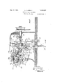
- Fig. 1 is a view partly in side elevation and partly in longitudinal section of a machine constructed according to a preferred embodiment of the present invention
- Fig. 2 is a horizontal section taken substantially upon the line 22 of Fig. 1, looking in the direction of the arrows
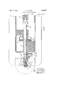
- Fig. 3 is a section taken substantially upon the line 33 of Fig. 4, looking in the direction ot the arrows
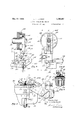
- Fig. l is an enlarged section taken substantially upon the line H of Fig. 1, looking in the direction of the arrows
- Fig. 5 is similarly an enlarged fragmentary elevation corresponding to Fig. 1
- Fig. 6 is a section taken upon the line 66 of F 5, looking in the direction of the arrows
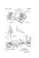
- FIG. 7 and 8 are enlarged perspective views illustrating the operation of the machine; 9 is a plan of a shoe upper, shown partly folded; Fig. 10 is a perspective of a lOQ shoe upper folded according to present-day methods; Fig. 11 is a detail view of the improved knife mechanism taken partly in section, substantially upon the line 11-11 of Fig. 1, looking in the direction of the arrows; and Fig. 12 is a section taken substantially upon the line 1212 of Fig. 11, looking in the direction of the arrows.
- a shoe upper is shown partly folded in Fig. 9.
- the margin 2 is intended to be folded upon the body 4 of the upper about a line of fold 6.
- the line along which the edge of the margin 2 will lie after the margin has been folded is indicated at 8.
- the margin 2 and the portion of the body of the upper bounded between the lines 6 and 8 have successive portions that are symmetrically disposed with respect to the line of fold 6. Two such symmetrically disposed portions are indicated at 10 and 12; the next succeeding two are indicated at 14 and 16; the next succeeding two at 18 and 20; the next succeeding two at 22 and 23; and so on throughout the margin of the upper, whether curved or straight.
- the portion 10 should obviously be folded into contact with its symmetrically disposed portion 12; the portion 14 into contact with its symmetrically disposed portion 16; and so on. In practice, however, the portion 10 is overlapped into contact with the portion 16; the portion 14 into contact with the portion 20; and so on, as is described more at length in a copending application, Serial No. 705,228, filed April 9, 1924.
- a chief object of the present invention is' to provide a new and improved method of and machine for folding the portion 10 accurately into contact with the portion 12; the portion 14 accurately into contact with the portion 16, as is illustrated in Fig. 9; and so on. No strains or creases will be introduced into the upper by this method of folding, so that the finally folded upper will be absolutely flat.
- the preferred mechanism for efiecting this result comprises two conical feed rolls 30 and 41 having oppositely disposed conical working surfaces that grip both sides of the margin 2 just after it has been folded by a folder or plow 32.
- the upper feed roll 30 is preferably positively rotated, and the lower feet roll is preferably loosely mounted in a fixed bearing bracket 61, being frictionally driven by the upper feed roll through the shoe-upper margin 2 interposed therebetween.
- the feed ing pull thus exerted upon the folded margin by the feed rolls is transmitted to the body 4 of the upperresting upon the support or table 24, and the body 4 is thus caused to follow the pulled margin 2 in the direction of feed.
- the successively pulled portions 10, 14, 18, 22, and so on are pulled forward in the direction of the arrow, Fig. 9.
- a fold presser 42 presses the folded portions of the margin into contact with the corresponding symmetrically disposed portions of the body 4 of the upper. The feed rolls thus not only feefil the stock, but they pull the margin as we.
- the feed roll 30 is mounted upon an inclined shaft 28 that is connected by a universal joint, like a ball and socket 110, with a horizontally disposed driving shaft 66.
- the shaft 28 is rotatable in a bearing 112 that is horizontally pivoted to the frame of the machine at 114.
- the feed roll 30 maythus be actuated into effective and ineffective positions by pivoting the bearing 112 about the pivot 114.
- the bearing 112 is provided upon one arm of a bell-crank lever, the other arm 116 of which is provided with an adjustable stop, shown as a set screw 118.
- the set screw 118 engages the upper end 120 of an arm 124 that is also pivoted at 114.
- a coil spring 126 disposed between the straddles.
- the limiting action of the spring 126 is adjusted not only by the set screw 118 but also by a stop, shown as a stop nut 1.30, threaded upon a rod 132 that extends through an opening in the arm 116 and is threaded into the portion 128 of the frame.
- the F- ring 126 is coiled about the rod 132.
- the arm 124 is oscillated about the pivot 114:. In one direction ot' oscillation, the upper end 120 engages the stop 118 and pivots the bearing 112 about the pivot 11%. The return movement is eitected by the spring 126.
- the arm 124. is linked at 134 to a rocking arm 136.
- the arm 136 is adapted to be rocked about a pivot 138 from the driving;- shaft 66.
- an interior cam 146 is fixed to the shaft 66 by a set screw 14-2. A. cam roll 1 1 1 rides in the interior cam 146.
- the cam roll 1 11 is pivoted at 146 to a bifurcated arm 148 that is caused to reciprocate vertically by a guide roll 150 that it
- the guide roll 150 is mounted upon a fixed pin 1f 2 extending from the frame of the machine.
- the arm 1&8 is pivoted at 160 to an adjustable link 162 the other end 163 of which is adjustably positioned in a groove 16% of the rocking arm 136.
- the movement of the cam roll 14:41 is thus conimuuicated through the link 162 and the rocking arm 136 to the arm 12a to cause the rais inc of the teed roll 30.
- the end 163 of the link 162 may be actuated in opposite directions by a knee lever 166 and a trcadle connected by a treadle rod 168.
- the knee lever and the treadle rod are both connected with a lever 169 pivoted at 170 and having a biturcatcd end 172 adapted to receive a projecting roll 17 1 of the link 162.
- the length of the feed strokes obviously depends upon the period 01": time, during; each cycle of operation of the cam 140, that the teed roll 30 remains in contact with the material.
- the pivot 160 occupies the level ot the line indicated at 177, Fig. 3, and the end 163 of the link 162 will occupy the level of the line indicated at 179.
- the points 160 and 163 will lie on the lines 181 and 183. respectively. and the teed roll will be out of contact with the material.
- the fold presser 12 is timed to operate with the Feed roll 30, so as to press the told when the feed roll 30 is ineffective and to be raised t'rom the work when the feed roll contacts therewith. This result is effected through the same rocking arm 136.
- the told presser 42 is carried upon a bell-crank arm 260 that is pivoted at 262.
- a bell-crank lever 163 that is linked to the arm 263 at 151 is yieldingly connected wita the arm 260 by a spring 165.
- the duration of operation of the fold presser during each cycle corresponds to the duration of ineffectiveness of the feed roll 30.
- a folder or plow :t'or initially folding the margin 2 prior to the action thereon of the feed rolls is positioned upon its support at a fixed point in the line of feed as shown at 32.
- the operatinp; instrumentalities of the machine should be arranged as compactly as possible.
- the bearing 112: and as the bearing is intermittently raised and lowered, in a direction at right angles to the direction of feed to render the feed intermio tently effective and ineliective, the connection of the plow 32 to the bearing is rendered resilient at 3 1, so that the plow yieldingly remains in contact with. the support irrespective of the operation of the bearing 112.
- the parts may be so adjusted, if de sired, that raising the hearing will result in the plow also during the actuation of feed means and the plow as a unit.
- the spring yield of the plow provides also for the passage of stock of creater thicknesses, such as at scams and the like.
- a retainer 153 is provided for holding the stock against movement during pauses in the feed.
- the retainer is normally springressed upward. as shown more particularly in Fig. 6. to clamp the stock against the lower to d roll 11.
- An arm 17 6 that is fixed to the bearing 11.2 engages an adjustable stop nut 178 upon the retainer arm 2 16 to actuate the retainer 153 downward, out of clamping engagement, when the feed roll 30 actuated into feeding relation to the feed roll e1.
- the retainer 153 is thus intermitiently rendered inefiective whenever the feed rolls are rendered eilective.
- the invention comprises also, in combination, a novel cutting mechanism for snipping the margin of the stock just after the folding operation.
- the cutting mechanism as such, and intended for use in more general tion.
- the snipping is performed, according to the preferred embodiment of the present invention, by a movable knife 352, cooperating with a stationary knife 354 to cut the foldmargin with a scissors-like action.
- the movable knife 352 is mounted upon a bell-crank lever 356 that is pivoted at 59 to the bracket 61.
- the other end of the bell-crank lever 356 is pivoted at 362 to a lever 364.
- the lever 364 is connected, as presently to be described, with a reciprocating lever 366.
- a tension spring 365 connecting the lever 366 with the frame of the machine normally tends to maintain the knife 352 in ineffective position.
- a stop 367 limits the action of the spring 365.
- the knife is normally ineffective.
- a projecting pin 368 upon a link 370 that connects the lever 366 to the frame at 372 is adapted to be engaged by a hook 373 to render the knife effective.
- the hook 37 3 is normally main tained out of engagement with the pin 368 by a spring 374. lVhen the hook 373 is rendered effective, the knife 352 is actuated through the lever 366 by a gear 152 to which the hook 372 is eccentrically connected at 150.
- gear 152 is driven from a gear 154 upon the driving shaft 66.
- the preferred construction comprises friction rolls 376 and 378 pivoted to the arm 364 at 380, the latter adapted to reciprocate in a direction inclined to the direction of reciprocation of the lever 366, and the former at right angles to the said direction.
- the inclined direction is indicated in Fig. 11 by the inclined guide groove 382, and the rightangular direction by the transversely disposed guide upon the lever 366.
- the groove 384 communicates with the groove 382.
- the feed roll is operated into and out of contact with the material in synchronism with the knife 352.
- the feedroll-carrying bearing 112 is connected with the knife-controlling arm 366 by a pin-andslot connection 392.
- Fig. 1 at the end of an upstanding portion 394 of the bearing.
- the knife 352 is ineffective, therefore, the feed roll 30 is in contact with the stock and the retainer and the fold Dresser are out of contact therewith.
- the feed roll remains in control to feed the material with feed strokes of a length different from the lengths obtained when the feed rolls are effective under other conditions, as described above. hen the knife is cutting, the fold presser and the retainer are both effective and the feed roll is ineffective.
- a gage 436 secured by a screw at 438, is provided rearward of the plow 32 for engaging the edge of the stock as it is fed into the machine. In order that concave portions of the stock may ride readily over the gage, as shown in Fig. 8, its rear portion is inclined to the plane of the support 24, as shown at 397.
- a method of feeding a shoe part or analogous flexible sheet material having a marginal portion standing out from and bent toward the body of the material that comprises pulling the bent marginal portion in substantially the direction of the line of bend and transmitting the pull from the marginal portion to the body to cause the body to fol. low the marginal portion, thereby to feed the material.
- a method of feeding a shoe upper having a marginal portion standing out from and folded toward and nearly in contact with the body of the material that comprises pulling the folded marginal portion in substantially the direction of the line of fold and transmitting the pull from the folded marginal portion to the body to cause the body to follow the folded marginal portion, thereby to feed the material.
- a method of feeding a shoe upper having a marginal portion standing out from and folded toward and nearly in contact with the body of the material along a substantially straight line of fold that comprises engaging both sides of the folded marginal portion with feed means advancing substantially in the direction of the substantially straight line of fold and transmitting the resultant pull upon the folded marginal. portion to the bodyto cause the body to follow the folded marginal portion, thereby to feed the material.
- a method of folding sheet material that comprises folding a marginal portion out from the body of the material, pulling the folded marginal portion substantially in the direction of the line of fold to feed the mate rial, transmitting the pull from the folded marginal portion to the body to cause the body to follow the folded marginal portion, and pressing the folded marginal portion against the body portion.
- a method of folding a shoe upper that comprises folding a marginal portion out from the body of the material, engaging both sides of the folded marginal portion, pulling the folded marginal portion substantially in the direction of the line of fold and transmitting the pull from the folded marginal portion to the body to cause the body to follow the folded marginal portion, and pressing the folded marginal portion against the body portion.
- a machine of the class described having, in combination, a support over which a shoe part or analogous flexible sheet material having a marginal portionstanding out from and bent toward the body of the material is adapted to be fed, and means for pulling the marginal portion substantially in the direction of the line of bend, whereby the pull from the marginal portion will become transmitted to the body to cause the body to follow the marginal portion, thereby to feed the material.
- a folding machine having, in combination, a support over which sheet material having a marginal portion folded out from the. body of the material is adapted to be fed, means for pulling the folded marginal portion substantially in the direction of the line of fold, whereby the pull from the folded mar ginal portion will become transmitted to the body to cause the body to follow th folded marginal portion, and means for pressing the folded marginal portion.
- a machine of the class described having, in combination, a support over which a shoe upper having a marginal portion standing out from and folded toward and nearly in contact with the body of the material is adapted to be fed, means for engaging both sides of the folded marginal portion, and means for advancing the engaging means substantially in the direction of the line of fold, whereby the resultant ull upon the folded marginal portion will become transmitted tothe body to cause the body to follow the folded marginal portion, thereby to feed thezmaterial.
- a machine of the class described having, in. combination, a support over which a shoe upper 11 aying a marginal portion standing out from and folded toward and nearly in contact with the body of the material, is adapted to be fed, and two feed rolls: constructed and arranged to engage both sides of the folded marginal portion to pull the folded marginal portion substantially in the direction of the line of fold, whereby the pull from the folded marginal portion will become transmitted to the body to cause the body to follow the folded marginal portion.
- a machine of the class described having, in combination, a support over which a shoe upper having a marginal portion standing out from and folded toward and nearly in contact with the body of the material is adapted to be fed, two feed rolls constructed and arranged to engage both sides of the folded marginal portion to pull the folded marginal portion substantially in the direction of the line of fold, whereby the pull from the folded marginal portion will become transmitted to the body to cause the body to follow the folded marginal portion, and means for driving one of the feed rolls.
- a machine of the class described having, in combination, a support over which sheet material having a margin folded out from the body of the material is adapted to be fed, and two tapering feed rolls constructed and arranged to engage both sides of the folded margin to pull the folded margin in the direction of feed, whereby the pull from the folded margin will become transmitted to the body to cause the body to follow the folded margin, the feed rolls being disposed with their tapers extending oppositely.
- a folding machine having, in combination, a support over which material is adapted to be fed, means for folding a margin of the material, a feed roll for feeding the material, means for continuously driving the feed roll, means for intermittently moving the feed roll into and out of contact with the material and means for maintaining the feed roll in contact with the material during time periods of unequal length.
- a machine of the class described having, in combination, a support over which material adapted to be fed, a shaft, a feed roll for feeding the material niiountcd upon the shaft, means for continuoush driving the feed roll from a source of power, and means for automatically actuating the shaft bodily with a pivotal movement to actuate the feed roll into and out of contact with the material.
- a machine of the class described having, in combination, a support over which material is adapted to be fed, a feed roll for feeding the material, means for continuously driving the feed'roll, means for automatically moving the feed roll intermittently into and out of contact with the. material, and means resiliently connecting the feed roll. and the moving means.
- a machine of the class described having, in combination, a support over which material is adapted to be fed, a plurality of cooperating means for gripping the material rial between them and to release the material,
- the retainlng means being ineffective when the cooperating means are relatively actuated towards each other to feed the material, and means controlled by one of the cooperating means when the cooperating means are relatlvely actuated from each other to release the material for causing the retaining means to become efi'ective.
- a machine of the class described having, in combination, a support over which material is adapted to be fed, two means for feeding the material, means cooperating with one of the feed means for retainingthe material against feeding movement when the feed means is ineffective, and means controlled by the other feed means for rendering the retaining means ineffective when the feed means is rendered effective.
- a machine of the class described having, in combination, means for feeding material, and a gage for gaging the material along its edge, the gage having an inclined face permitting the material to ride over the gage.
- a folding machine having, in combination, a support over which sheet material is adapted to be fed, means for folding a margin out from the body of the material. means for engaging both sides of the folded margin, and means for actuating the engaging means to pull the folded margin in the direction of feed, whereby the pull from the folded margin will become transmitted to the body to cause the body to follow the folded margin.
- a folding machine having, in combination, a support over which sheet material is adapted to be fed, means for folding a margin out from the body of the material, and means for pulling the folded margin in the direction of feed, whereby the pull from the folded margin will become transmitted to the,
- a folding machine having, in combination, a support over which sheet material is adapted to be fed, means for folding a margin out from the body of the material, means for pulling the folded margin in the direction of feed, whereby the pull from the folded margin will become'transmitted to the body to cause the body to follow the foldedmargin, and means for pressing the folded margin.
- a folding machine having, in combination, a support over which sheet material is adapted to be fed, means for folding a margin of the material, and two feed rolls constructed and arranged to engage both sides of the folded margin to pull the folded margin in the direction of feed, whereby the pull from the folded margin will become transmitted to the body of the material to cause the body to follow the folded margin.
- a folding machine having, in combination, a support over which sheet material is adapted to be fed, means for folding a margin of the material, two feed rolls con structed and arranged to engage both sides of [the folded margin to pull the folded margin in the direction of feed, whereby the pull from the folded margin will become transmitted to the body of the material to cause the body to follow the folded margin, and means for driving one of the feed rolls.
- a folding machine having, in combination, a support over which sheet material is adapted to be fed, means for folding a margin of the material, and two tapering feed rolls constructed and arranged to engage both sides of the folded margin to pull the folded margin in the direction of feed, whereby the pull from the folded margin will be come transmitted to the body of the material to cause the body to follow the folded margin, the feed rolls being disposed with their tapers extending oppositely.
- a folding machine having, in combination, a support over which sheet material is adapted to be fed, means for folding a mar-i gin of the material, a feed roll for feeding the material, means for continuously driving the feed roll, means for actuating the feed roll into and out of contact with the material, and means formaintaining thefeed roll in contact with the material during time periods of unequal length.
- a folding machine having, in combination, a support over which sheet material is adapted to be fed, means for folding a margm of the material, a shaft driven from a source. of power, a feed roll for feeding the material mounted upon the shaft, and means for pivotally actuating the shaft relative to the source of power to actuate the feed roll into and out of contact with the material.
- a folding machine having, in combination, a support over which sheet material is adapted to be fed, means for folding a margin of the material, means for feeding the material, means for actuating the feed means to feed the material by different feed strokes, means for pressing the fold formed by the folding means, and means controlled by the actuating means for controlling the pressing means.
- a folding machine having, in comblnation, a support over which sheet material is adapted to be fed, means for folding a margin of the material, means for feeding the material, means for actuating the feed means to feed the material bv different feed strokes, means for pressing the fold formed by the folding means, and means controlled by the actuating means for varying the operation of the pressing means.
- a folding machine having, in combination, a support over which material is adapted to be fed, means for folding the material, means for feeding the material, means for actuating the feed means into and out of contact with the material, and means whereby the folding means is adapted to be actuated as a unit with the feed means dun ing the actuation of the feed means into and out of contact with the material.
- a folding machine having, in combination, a support over which material is adapted to be fed, means for feeding the material, and means carried by the feed means at a fixed position in the line of feed for folding the material.
- a folding machine having, in combination, means for feeding material, means for folding the material, and means for piv otally actuating the feed means and the folding means as a unit at right angles to the direction of feed.
- a folding machine having, in combination, means for feeding material, means for folding the material, means for actuating the feed means and the folding means as a unit at right angles to the direction of feed, and means whereby the folding means is adapted to yield with respect to the feed means during the actuation of the feed means and the folding means as aunit.
- a folding machine having, in combination, a support over which material is adapted to be fed, means for feeding the material, means for actuating the feed means into and out of contact with the material, means carried by the feed means for folding the material, and means whereby the folding means is maintained in contact with the support during the actuation of the feed tion, a support over which material is adapted to be fed, means for feeding the material, means for actuating the feed means into and out of contact with the material, and means carried by the feed means and supported on the support for folding the material, there being a resilient connection between the folding means and the feed means, whereby the folding means is maintained in contact with the support during the actuation of the feed means into and out of contact with the material.
- a folding machine having, in combination, a support over which. material is adapted to be fed, means for feeding the material, means for folding the material, means for retaining the material against feeding movement, and means controlled by the feed means for controlling the retaining means.
- a folding machine having, in combination, a support over which material is adapted to be fed, means for feeding the material, means carried by the feed means for folding the material, means for retaining the material against feeding movement, and
- a folding machine having, in combination, a support over which material is adapted to be fed, means for feeding the ma terial, means for actuating the feed 'means into and out of contact with the material, means for folding the material, means for retaining the material against feeding movement when the feed means is actuated out of contact with the material, and means controlled by the feed means for rendering the retaining means ineffective when the feed means is actuated into contact with the material.
- a folding machine having, in combination, a support over which material is adapted to be fed, two feed rolls for feeding the material, means for driving one of the feed rolls, means for folding the material, means for clamping the material against the other feed roll when the food rolls are ineffective, and means for rendering the clamping means ineffective when the feed rolls are effective.
- a folding machine having, in combination, a support over which material is adapted to be fed, means for folding the terial, means for cutting the material, and means controlled by the cutting means for feeding the material.
Landscapes
- Folding Of Thin Sheet-Like Materials, Special Discharging Devices, And Others (AREA)
Description
Dec. 17, 192 9.
L. J. LAMBERT FOLDING MACHINE AND METHOD Filed Aug. 27, 1925 4 Sheets-Sheet l [amen far Leo Jlambe1;t
Dec. 17, 1929. L. J. LAMBERT FOLDING MACHINE AND METHOD Filed Aug. 27, 1925 I 4 Sheets-Sheet @t t own, 6 9' Dec. 17, 1929.
L. J. LAMBERT 1,740,407
FOLDING MACHINE AND METHOD Filed Aug. 27, 1925 ln/vargtm" Leo JLmber fi 4 Sheets-Sheet 4 Fatented Eon 17, 1929 airs STAES T NT I LEO J. LAMBERT, OF SALEM, MASSACHUSETTS, ASSIGNOR, BY ASSIGNMENTS,
TO UNITED SHOE MAGHINERY CORPORATION, OF .PATEBSGN, NEW JERSEY, A (301%- LPOBATION .013 NEW JERSEY Application filed August 27, 1925.
'l he present invention relates to methods of and machines ror 'tolding flexible material, and more particularly to methods or" and machines for folding the margins of shoe uppers, such as vamps, quarters, tongues and the like.
Folding machines of the above-described character, of the s,tep-by-step-teed type, are generally provided with a folder .or plow for 19 initiatinga told in successive portions of the margin of the shoe upper, and with a fold presser that presses down the successive folds thus initiated into contact with the body of the upper. It is desirable that the contacting partslot the margin and of the body of the upper be symmetrically disposed to the line of fold. In practice, however, whether the folding be done by machines of the abovedescribed character, or :by hand, such symmetrical folding is not attainable. During each folding action of :the plow, the yet unfolded portions of the margin exert a pullliorce upon the portion that is in the act of being folded and this pulling force causes the fold to be pressed down upon a portion of the abody of the upper that is a little to one side of its symmetrically disposed portion. The consequence of this unsymmetrical tolding is that the folded upper Will not lie flat, but is more or less twisted. If the upper is of substantial width, as in the case of vamps and quarters, and as the twisting effect is confined almost entirely to the folded marginal portion, the twist s not very noticeable. The twist thus produced in very narrow uppers, however, like tongues, straps, and the like, may be Very great.
It is accordingly an object of the present invention ,to provide a new and improved method of and machine for folding the mar gins of shoe uppers without introducing the above-described twist.
lVith this end in view, a feature of the invention resides in pulling upon successive portions of the folded margin to feed the material, the pull being transmitted from the folded margin to the body of the material. The pull thus exerted upon the margin is naturally a direction opposed to the direc- Serial No. 52,849.
tion of the pull exerted by the yet unfolded portion of the margin.
A further object is to provide a novel mechanism for effecting the said controlled pulling action and feeding.
A further object is to provide an improved mechanism for facilitating the turning of portions of the material having curved margins, and with this object in view, a feature of the invention contemplates a new and improved construction in which the operative parts of the machine are very compactly arranged.
Another object is to provide an improved cutting mechanism for snipping the margin, at the will of the operator, prior to the folding operation.
Still another object is to simplify the construction of folding machines, reducing their cost of manufacture and rendering them more efficient in operation.
Other and further objects will be explained in the following description, and will be particularly pointed out in the appended claims, it being understood that the invention consists of the folding method and machine a preferred embodiment of which is illustrated and described herein, and that it is intended to express in the appendedclaims all the novelty that the invention may possess.
1n the accompanying drawings, Fig. 1 is a view partly in side elevation and partly in longitudinal section of a machine constructed according to a preferred embodiment of the present invention; Fig. 2 is a horizontal section taken substantially upon the line 22 of Fig. 1, looking in the direction of the arrows; Fig. 3 is a section taken substantially upon the line 33 of Fig. 4, looking in the direction ot the arrows; Fig. l is an enlarged section taken substantially upon the line H of Fig. 1, looking in the direction of the arrows; Fig. 5 is similarly an enlarged fragmentary elevation corresponding to Fig. 1; Fig. 6 is a section taken upon the line 66 of F 5, looking in the direction of the arrows; Figs. 7 and 8 are enlarged perspective views illustrating the operation of the machine; 9 is a plan of a shoe upper, shown partly folded; Fig. 10 is a perspective of a lOQ shoe upper folded according to present-day methods; Fig. 11 is a detail view of the improved knife mechanism taken partly in section, substantially upon the line 11-11 of Fig. 1, looking in the direction of the arrows; and Fig. 12 is a section taken substantially upon the line 1212 of Fig. 11, looking in the direction of the arrows.
A shoe upper is shown partly folded in Fig. 9. The margin 2 is intended to be folded upon the body 4 of the upper about a line of fold 6. The line along which the edge of the margin 2 will lie after the margin has been folded is indicated at 8. The margin 2 and the portion of the body of the upper bounded between the lines 6 and 8 have successive portions that are symmetrically disposed with respect to the line of fold 6. Two such symmetrically disposed portions are indicated at 10 and 12; the next succeeding two are indicated at 14 and 16; the next succeeding two at 18 and 20; the next succeeding two at 22 and 23; and so on throughout the margin of the upper, whether curved or straight.
The portion 10 should obviously be folded into contact with its symmetrically disposed portion 12; the portion 14 into contact with its symmetrically disposed portion 16; and so on. In practice, however, the portion 10 is overlapped into contact with the portion 16; the portion 14 into contact with the portion 20; and so on, as is described more at length in a copending application, Serial No. 705,228, filed April 9, 1924. The reason why this overlapping folding occurs will be readily understood when it is reflected that, during the folding of the portion 10 toward the portion 12, the yet unfolded portions 14, 18, 22 and so on, of the margin 2 pull upon the portion 10 to displace it towards the portion 16; during the folding of the portion 14 toward the portion 16, the yet unfolded por tions 18, 22, and so 011, of the margin 2 pull upon the portion 14 to displace it towards the portion 20; and so on. Vhen the margin 2 is finally folded, the resulting strains set up in the folded margin will cause the upper to twist, as is illustrated in Fig. 10. Objectionable creases are also produced.
A chief object of the present invention is' to provide a new and improved method of and machine for folding the portion 10 accurately into contact with the portion 12; the portion 14 accurately into contact with the portion 16, as is illustrated in Fig. 9; and so on. No strains or creases will be introduced into the upper by this method of folding, so that the finally folded upper will be absolutely flat.
erted by the portions 14, 18, 22, and so on, of the yet unfolded margin 2. The portion 10 is thus folded flat into contact with the portion 12. A similar pull in the direction of the arrow, when folding the portion 14, will result in the portion 14 being folded flat into contact with the portion 16; and so on.
The preferred mechanism for efiecting this result comprises two conical feed rolls 30 and 41 having oppositely disposed conical working surfaces that grip both sides of the margin 2 just after it has been folded by a folder or plow 32. The upper feed roll 30 is preferably positively rotated, and the lower feet roll is preferably loosely mounted in a fixed bearing bracket 61, being frictionally driven by the upper feed roll through the shoe-upper margin 2 interposed therebetween. The feed ing pull thus exerted upon the folded margin by the feed rolls is transmitted to the body 4 of the upperresting upon the support or table 24, and the body 4 is thus caused to follow the pulled margin 2 in the direction of feed. By reason of this pulling effect upon the margin 2, aided by the friction of the body 4 of the upper againstithe support 24, the successively pulled portions 10, 14, 18, 22, and so on, are pulled forward in the direction of the arrow, Fig. 9. By adjusting the degree of pulling action, the successively pulled portions of the margin may be caused to become superposed directly over the cor-j responding symmetrically disposed portions of the body of the upper. A fold presser 42 presses the folded portions of the margin into contact with the corresponding symmetrically disposed portions of the body 4 of the upper. The feed rolls thus not only feefil the stock, but they pull the margin as we.
As some portions of the margin 2 must be ment will now be explained. The feed roll 30 is mounted upon an inclined shaft 28 that is connected by a universal joint, like a ball and socket 110, with a horizontally disposed driving shaft 66. The shaft 28 is rotatable in a bearing 112 that is horizontally pivoted to the frame of the machine at 114. The feed roll 30 maythus be actuated into effective and ineffective positions by pivoting the bearing 112 about the pivot 114. The bearing 112 is provided upon one arm of a bell-crank lever, the other arm 116 of which is provided with an adjustable stop, shown as a set screw 118. The set screw 118 engages the upper end 120 of an arm 124 that is also pivoted at 114. A coil spring 126 disposed between the straddles.
frame of the machine at 128, Fig. 1, and the arm 116, tends to maintain the feed roll in effective position. The limiting action of the spring 126 is adjusted not only by the set screw 118 but also by a stop, shown as a stop nut 1.30, threaded upon a rod 132 that extends through an opening in the arm 116 and is threaded into the portion 128 of the frame. The F- ring 126 is coiled about the rod 132.
To more the feed roll 30 into and out of elt'ective feeding position, the arm 124: is oscillated about the pivot 114:. In one direction ot' oscillation, the upper end 120 engages the stop 118 and pivots the bearing 112 about the pivot 11%. The return movement is eitected by the spring 126. The arm 124. is linked at 134 to a rocking arm 136. The arm 136 is adapted to be rocked about a pivot 138 from the driving;- shaft 66. To this end, an interior cam 146 is fixed to the shaft 66 by a set screw 14-2. A. cam roll 1 1 1 rides in the interior cam 146. The cam roll 1 11 is pivoted at 146 to a bifurcated arm 148 that is caused to reciprocate vertically by a guide roll 150 that it The guide roll 150 is mounted upon a fixed pin 1f 2 extending from the frame of the machine. The arm 1&8 is pivoted at 160 to an adjustable link 162 the other end 163 of which is adjustably positioned in a groove 16% of the rocking arm 136. The movement of the cam roll 14:41 is thus conimuuicated through the link 162 and the rocking arm 136 to the arm 12a to cause the rais inc of the teed roll 30. The end 163 of the link 162 may be actuated in opposite directions by a knee lever 166 and a trcadle connected by a treadle rod 168. The knee lever and the treadle rod are both connected with a lever 169 pivoted at 170 and having a biturcatcd end 172 adapted to receive a projecting roll 17 1 of the link 162.
The length of the feed strokes obviously depends upon the period 01": time, during; each cycle of operation of the cam 140, that the teed roll 30 remains in contact with the material. Vl' hen the link 162 occupies the position illustrated in Fig. 3, the feed roll 30 will be in contact with the material during the comparatively short period when the cam roll 14 1 occupies the dwell 175, l. At this time, the pivot 160 occupies the level ot the line indicated at 177, Fig. 3, and the end 163 of the link 162 will occupy the level of the line indicated at 179. During the remainder ot the cycle of operation. the points 160 and 163 will lie on the lines 181 and 183. respectively. and the teed roll will be out of contact with the material.
When the link 162 occupies its other etctreme position, the center of its end 163 will be positioned at 185, and this will cause the arm 136 to assume a position such that the feed roll 30' will be out of contact with the material when the cam roll 114 occupies the dwell 175. During the remainder of the cycle of operation, the feed roll 30 will be in contact with the material, and the material will thus be fed thr ughout the greater portion of the cycle.
The latter, or long-stroke feed will be used on straight and nearly straight margins, and the former on sharply curved margins, where a short-stroke feed is desirable. All that the operator has to do to obtain a long-stroke feed is to actuate the treadle rod 168; and a short-stroke teed results when the knee lever 166 is actuated in the opposite direction.
The fold presser 12 is timed to operate with the Feed roll 30, so as to press the told when the feed roll 30 is ineffective and to be raised t'rom the work when the feed roll contacts therewith. This result is effected through the same rocking arm 136. The told presser 42 is carried upon a bell-crank arm 260 that is pivoted at 262. A bell-crank lever 163 that is linked to the arm 263 at 151 is yieldingly connected wita the arm 260 by a spring 165. The duration of operation of the fold presser during each cycle corresponds to the duration of ineffectiveness of the feed roll 30.
A folder or plow :t'or initially folding the margin 2 prior to the action thereon of the feed rolls is positioned upon its support at a fixed point in the line of feed as shown at 32. In order to turn sharply curved portions of the margin during folding, the operatinp; instrumentalities of the machine should be arranged as compactly as possible. As there is not smlicient room upon the support for securing" the plow 32 thereto in the position indicated, it is car ied by the bearing; 112: and as the bearing is intermittently raised and lowered, in a direction at right angles to the direction of feed to render the feed intermio tently effective and ineliective, the connection of the plow 32 to the bearing is rendered resilient at 3 1, so that the plow yieldingly remains in contact with. the support irrespective of the operation of the bearing 112. Of course. the parts may be so adjusted, if de sired, that raising the hearing will result in the plow also during the actuation of feed means and the plow as a unit. The spring yield of the plow provides also for the passage of stock of creater thicknesses, such as at scams and the like.
A retainer 153 is provided for holding the stock against movement during pauses in the feed. The retainer is normally springressed upward. as shown more particularly in Fig. 6. to clamp the stock against the lower to d roll 11. An arm 17 6 that is fixed to the bearing 11.2 engages an adjustable stop nut 178 upon the retainer arm 2 16 to actuate the retainer 153 downward, out of clamping engagement, when the feed roll 30 actuated into feeding relation to the feed roll e1. The retainer 153 is thus intermitiently rendered inefiective whenever the feed rolls are rendered eilective.
The invention comprises also, in combination, a novel cutting mechanism for snipping the margin of the stock just after the folding operation. The cutting mechanism as such, and intended for use in more general tion. The snipping is performed, according to the preferred embodiment of the present invention, by a movable knife 352, cooperating with a stationary knife 354 to cut the foldmargin with a scissors-like action. The movable knife 352 is mounted upon a bell-crank lever 356 that is pivoted at 59 to the bracket 61. The other end of the bell-crank lever 356 is pivoted at 362 to a lever 364. The lever 364 is connected, as presently to be described, with a reciprocating lever 366. A tension spring 365 connecting the lever 366 with the frame of the machine normally tends to maintain the knife 352 in ineffective position. A stop 367 limits the action of the spring 365.
. The knife is normally ineffective. A projecting pin 368 upon a link 370 that connects the lever 366 to the frame at 372 is adapted to be engaged by a hook 373 to render the knife effective. The hook 37 3 is normally main tained out of engagement with the pin 368 by a spring 374. lVhen the hook 373 is rendered effective, the knife 352 is actuated through the lever 366 by a gear 152 to which the hook 372 is eccentrically connected at 150. The
As the knives 352. 354 operate in a plane inclined to the direction of reciprocation of the lever 366, it is necessary that the arm 364 :have a lost-motion connection with the lever The preferred construction comprises friction rolls 376 and 378 pivoted to the arm 364 at 380, the latter adapted to reciprocate in a direction inclined to the direction of reciprocation of the lever 366, and the former at right angles to the said direction. The inclined direction is indicated in Fig. 11 by the inclined guide groove 382, and the rightangular direction by the transversely disposed guide upon the lever 366. The groove 384 communicates with the groove 382. The
extreme positions. In such midway position, the cam roll 144 will cause the end 163 of the link 162 to oscillate idly between the Walls 389 and 390, Fig. 3, of the rocking arm 136, producing no effect upon the feed roll 30.
At such time the feed roll is operated into and out of contact with the material in synchronism with the knife 352. The feedroll-carrying bearing 112 is connected with the knife-controlling arm 366 by a pin-andslot connection 392. Fig. 1, at the end of an upstanding portion 394 of the bearing. hen the knife 352 is ineffective, therefore, the feed roll 30 is in contact with the stock and the retainer and the fold Dresser are out of contact therewith. The feed roll remains in control to feed the material with feed strokes of a length different from the lengths obtained when the feed rolls are effective under other conditions, as described above. hen the knife is cutting, the fold presser and the retainer are both effective and the feed roll is ineffective.
A gage 436, secured by a screw at 438, is provided rearward of the plow 32 for engaging the edge of the stock as it is fed into the machine. In order that concave portions of the stock may ride readily over the gage, as shown in Fig. 8, its rear portion is inclined to the plane of the support 24, as shown at 397.
Modifications will readily occur to persons skilled in the art, and all such are considered to fall within the spirit and scope of the invention, as defined in the appended claims.
hat is claimed is:
1. A method of feeding a shoe part or analogous flexible sheet material having a marginal portion standing out from and bent toward the body of the material that comprises pulling the bent marginal portion in substantially the direction of the line of bend and transmitting the pull from the marginal portion to the body to cause the body to fol. low the marginal portion, thereby to feed the material.
2. A method of feeding a shoe upper having a marginal portion standing out from and folded toward and nearly in contact with the body of the material that comprises pulling the folded marginal portion in substantially the direction of the line of fold and transmitting the pull from the folded marginal portion to the body to cause the body to follow the folded marginal portion, thereby to feed the material.
3. A method of feeding a shoe upper having a marginal portion standing out from and folded toward and nearly in contact with the body of the material along a substantially straight line of fold that comprises engaging both sides of the folded marginal portion with feed means advancing substantially in the direction of the substantially straight line of fold and transmitting the resultant pull upon the folded marginal. portion to the bodyto cause the body to follow the folded marginal portion, thereby to feed the material.
4. A method of folding sheet material that comprises folding a marginal portion out from the body of the material, pulling the folded marginal portion substantially in the direction of the line of fold to feed the mate rial, transmitting the pull from the folded marginal portion to the body to cause the body to follow the folded marginal portion, and pressing the folded marginal portion against the body portion.
5. A method of folding a shoe upper that comprises folding a marginal portion out from the body of the material, engaging both sides of the folded marginal portion, pulling the folded marginal portion substantially in the direction of the line of fold and transmitting the pull from the folded marginal portion to the body to cause the body to follow the folded marginal portion, and pressing the folded marginal portion against the body portion.
6. A machine of the class described having, in combination, a support over which a shoe part or analogous flexible sheet material having a marginal portionstanding out from and bent toward the body of the material is adapted to be fed, and means for pulling the marginal portion substantially in the direction of the line of bend, whereby the pull from the marginal portion will become transmitted to the body to cause the body to follow the marginal portion, thereby to feed the material.
7. A folding machine having, in combination, a support over which sheet material having a marginal portion folded out from the. body of the material is adapted to be fed, means for pulling the folded marginal portion substantially in the direction of the line of fold, whereby the pull from the folded mar ginal portion will become transmitted to the body to cause the body to follow th folded marginal portion, and means for pressing the folded marginal portion.
8. A machine of the class described having, in combination, a support over which a shoe upper having a marginal portion standing out from and folded toward and nearly in contact with the body of the material is adapted to be fed, means for engaging both sides of the folded marginal portion, and means for advancing the engaging means substantially in the direction of the line of fold, whereby the resultant ull upon the folded marginal portion will become transmitted tothe body to cause the body to follow the folded marginal portion, thereby to feed thezmaterial.
9. A machine of the class described having, in. combination, a support over which a shoe upper 11 aying a marginal portion standing out from and folded toward and nearly in contact with the body of the material, is adapted to be fed, and two feed rolls: constructed and arranged to engage both sides of the folded marginal portion to pull the folded marginal portion substantially in the direction of the line of fold, whereby the pull from the folded marginal portion will become transmitted to the body to cause the body to follow the folded marginal portion.
10. A machine of the class described having, in combination, a support over which a shoe upper having a marginal portion standing out from and folded toward and nearly in contact with the body of the material is adapted to be fed, two feed rolls constructed and arranged to engage both sides of the folded marginal portion to pull the folded marginal portion substantially in the direction of the line of fold, whereby the pull from the folded marginal portion will become transmitted to the body to cause the body to follow the folded marginal portion, and means for driving one of the feed rolls.
11. A machine of the class described having, in combination, a support over which sheet material having a margin folded out from the body of the material is adapted to be fed, and two tapering feed rolls constructed and arranged to engage both sides of the folded margin to pull the folded margin in the direction of feed, whereby the pull from the folded margin will become transmitted to the body to cause the body to follow the folded margin, the feed rolls being disposed with their tapers extending oppositely.
12. A folding machine having, in combination, a support over which material is adapted to be fed, means for folding a margin of the material, a feed roll for feeding the material, means for continuously driving the feed roll, means for intermittently moving the feed roll into and out of contact with the material and means for maintaining the feed roll in contact with the material during time periods of unequal length.
13. A machine of the class described having, in combination, a support over which material adapted to be fed, a shaft, a feed roll for feeding the material niiountcd upon the shaft, means for continuoush driving the feed roll from a source of power, and means for automatically actuating the shaft bodily with a pivotal movement to actuate the feed roll into and out of contact with the material.
14. A machine of the class described having, in combination, a support over which material is adapted to be fed, a feed roll for feeding the material, means for continuously driving the feed'roll, means for automatically moving the feed roll intermittently into and out of contact with the. material, and means resiliently connecting the feed roll. and the moving means.
I5. A machine of the class describedhaving, in combination, a support over which material is adapted to be fed, a plurality of cooperating means for gripping the material rial between them and to release the material,
means for retaining the material against feeding movement, the retainlng means being ineffective when the cooperating means are relatively actuated towards each other to feed the material, and means controlled by one of the cooperating means when the cooperating means are relatlvely actuated from each other to release the material for causing the retaining means to become efi'ective.
16. A machine of the class described having, in combination, a support over which material is adapted to be fed, two means for feeding the material, means cooperating with one of the feed means for retainingthe material against feeding movement when the feed means is ineffective, and means controlled by the other feed means for rendering the retaining means ineffective when the feed means is rendered effective.
17. A machine of the class described having, in combination, a support over which material is adapted to be fed, two feed rolls for feeding the material, means for intermittently rendering the feed rolls effective, means for clamping the material against one of the feed rolls when the feed rolls are inefiective, and means for rendering the clamping means ineffectivewhen the feel rolls are effective.
18. A machine of the class described having, in combination, a support over which material is adapted to be fed, means for feeding'the material, means for intermittently moving the feed means into and out of con 'tact with the material, and means actuable to one limit of movement to maintain the feed means in contact with the material dur ing a predetermined time interval and out of contact with the material during a second predetermined time interval, and actuable to another limit of movement to reverse the time intervals.
19. A machine of the class described having, in combination, means for feeding material, and a gage for gaging the material along its edge, the gage having an inclined face permitting the material to ride over the gage.
20. A folding machine having, in combination, a support over which sheet material is adapted to be fed, means for folding a margin out from the body of the material. means for engaging both sides of the folded margin, and means for actuating the engaging means to pull the folded margin in the direction of feed, whereby the pull from the folded margin will become transmitted to the body to cause the body to follow the folded margin.
21. A folding machine having, in combination, a support over which sheet material is adapted to be fed, means for folding a margin out from the body of the material, and means for pulling the folded margin in the direction of feed, whereby the pull from the folded margin will become transmitted to the,
body to cause the body to follow the folded margin.
22. A folding machine having, in combination, a support over which sheet material is adapted to be fed, means for folding a margin out from the body of the material, means for pulling the folded margin in the direction of feed, whereby the pull from the folded margin will become'transmitted to the body to cause the body to follow the foldedmargin, and means for pressing the folded margin. V
23. A folding machine having, in combination, a support over which sheet material is adapted to be fed, means for folding a margin of the material, and two feed rolls constructed and arranged to engage both sides of the folded margin to pull the folded margin in the direction of feed, whereby the pull from the folded margin will become transmitted to the body of the material to cause the body to follow the folded margin.
24. A folding machine having, in combination, a support over which sheet material is adapted to be fed, means for folding a margin of the material, two feed rolls con structed and arranged to engage both sides of [the folded margin to pull the folded margin in the direction of feed, whereby the pull from the folded margin will become transmitted to the body of the material to cause the body to follow the folded margin, and means for driving one of the feed rolls.
25. A folding machine having, in combination, a support over which sheet material is adapted to be fed, means for folding a margin of the material, and two tapering feed rolls constructed and arranged to engage both sides of the folded margin to pull the folded margin in the direction of feed, whereby the pull from the folded margin will be come transmitted to the body of the material to cause the body to follow the folded margin, the feed rolls being disposed with their tapers extending oppositely.
26. A folding machine having, in combination, a support over which sheet material is adapted to be fed, means for folding a mar-i gin of the material, a feed roll for feeding the material, means for continuously driving the feed roll, means for actuating the feed roll into and out of contact with the material, and means formaintaining thefeed roll in contact with the material during time periods of unequal length.
27. A folding machine having, in combination, a support over which sheet material is adapted to be fed, means for folding a margm of the material, a shaft driven from a source. of power, a feed roll for feeding the material mounted upon the shaft, and means for pivotally actuating the shaft relative to the source of power to actuate the feed roll into and out of contact with the material.
28. A folding machine having, in combination, a support over which sheet material is adapted to be fed, means for folding a margin of the material, a feed roll for feeding the material, means for continuously driving the feed roll, and means for intermittently moving the feed roll into and out of contact with the material.
29. A folding machine having, in combination, a support over which sheet material is adapted to be fed, means for folding a margin of the material, means for feeding the material, means for actuating the feed means to feed the material by different feed strokes, means for pressing the fold formed by the folding means, and means controlled by the actuating means for controlling the pressing means.
30. A folding machine having, in comblnation, a support over which sheet material is adapted to be fed, means for folding a margin of the material, means for feeding the material, means for actuating the feed means to feed the material bv different feed strokes, means for pressing the fold formed by the folding means, and means controlled by the actuating means for varying the operation of the pressing means.
31. A folding machine having, in combination, a support over which sheet material is adapted to be fed, means for folding a margin of the material, two feed rolls constructed and arranged to engage both sides of the folded margin to pull the folded margin in the direction of feed, whereby the pull from the folded margin will become transmitted to the body of the material to cause the body to follow the folded margin, means for continuously driving one of the feed rolls, a rocking arm for actuating the said one feed roll into and out of contact with the material, means for rocking the arm, and means for connecting the rocking means with different portions of the arm to cause the feed roll to feed the material with feed strokes of different length.
32. A folding machine having, in combination, support over which sheet material is adapted to be fed, means for folding a margin of the material, a feed roll for feeding the material, means for continuously drivin the feed roll, means for intermittently moving the feed roll into and out of contact with the material, and means yieldingly connecting the feed roll and the moving means.
33. A folding machine having, in combination, a support over which material is adapted to be fed, means for folding the material, means for feeding the material, means for actuating the feed means into and out of contact with the material, and means whereby the folding means is adapted to be actuated as a unit with the feed means dun ing the actuation of the feed means into and out of contact with the material.
34. A folding machine having, in combination, a support over which material is adapted to be fed, means for feeding the material, and means carried by the feed means at a fixed position in the line of feed for folding the material.
35. A folding machine having, in combination, means for feeding material, means for folding the material, and means for piv otally actuating the feed means and the folding means as a unit at right angles to the direction of feed.
86. A folding machine having, in combination, means for feeding material, means for folding the material, means for actuating the feed means and the folding means as a unit at right angles to the direction of feed, and means whereby the folding means is adapted to yield with respect to the feed means during the actuation of the feed means and the folding means as aunit.
37. A folding machine having, in combination, a support over which material is adapted to be fed, means for feeding the material, means for actuating the feed means into and out of contact with the material, means carried by the feed means for folding the material, and means whereby the folding means is maintained in contact with the support during the actuation of the feed tion, a support over which material is adapted to be fed, means for feeding the material, means for actuating the feed means into and out of contact with the material, and means carried by the feed means and supported on the support for folding the material, there being a resilient connection between the folding means and the feed means, whereby the folding means is maintained in contact with the support during the actuation of the feed means into and out of contact with the material.
39. A folding machine having, in combination, a support over which. material is adapted to be fed, means for feeding the material, means for folding the material, means for retaining the material against feeding movement, and means controlled by the feed means for controlling the retaining means.
40. A folding machine having, in combination, a support over which material is adapted to be fed, means for feeding the material, means carried by the feed means for folding the material, means for retaining the material against feeding movement, and
means controlled by the feed means for controlling the retaining means.
41. A folding machine having, in combination, a support over which material is adapted to be fed, means for feeding the ma terial, means for actuating the feed 'means into and out of contact with the material, means for folding the material, means for retaining the material against feeding movement when the feed means is actuated out of contact with the material, and means controlled by the feed means for rendering the retaining means ineffective when the feed means is actuated into contact with the material.
42. A folding machine having, in combination, a support over which material is adapted to be fed, two feed rolls for feeding the material, means for driving one of the feed rolls, means for folding the material, means for clamping the material against the other feed roll when the food rolls are ineffective, and means for rendering the clamping means ineffective when the feed rolls are effective.
43. A folding machine having, in combination, a support over which material is adapted to be fed, means for folding the terial, means for cutting the material, and means controlled by the cutting means for feeding the material.
44. A folding machine having, in combi-' nation, a support over which material is adapted to be fed, means for folding the material, means for feeding the material,
means for cutting .the material, means for rendering the feed means effective, and means controlled by the cutting means for rendering the feed means effective.
45. A folding machine having, in combination, a support over which material is adapted to be fed, means for folding the material, means for feeding the material, a knife disposed in a plane at an angle to the line of feed for cutting the material, means adapted to reciprocate in a direction at an angle to the plane for actuating the knife, and a lost-motion connection between the knife and the re ciprocating means.
46. A folding machine having, in combination, a support over which material is adapted to be fed, means for folding the material, means for feeding the material, a knife. for cutting the material, a reciprocating member for actuating the knife, a member reciprocating at an angle to the first-named member for actuating the first-named member, the secondnamed member having a groove, and a third member having a lost-motion connection with .the second-named member and a groove communicating with the first-named groove disposed along the line of reciprocation of the first-named member, the first-named member having portions in the grooves.
47. A folding machine having, in combination, means for feeding material, a gage for gaging the material along its edge, and means for folding the material, the gage having an inclined face permitting curved portions of the material to ride over the gage.
48. A folding machine having, in combination, a support over which sheet material is adapted to be fed, means for folding a margin out from the body of the material, means for engaging both sides of the folded margin, means for actuating the engaging means to pull the folded margin in the direction of feed, whereby the pull from the folded margin will become transmitted to the body to cause the body to follow the folded margin, means for cutting the material, and means controlled by the cutting means for rendering the engaging means effective.
49. A folding machine having, in combination, a support over which sheet material is adapted to be fed, means for folding a margin out from the body of the material, means for pulling the folded margin in the direction of feed, whereby the pull from the folded margin will become transmitted to the body to cause the body to follow the folded margin, means for cutting the material and means controlled by the cutting means for rendering the pulling means effective.
50. A folding machine having, in combination, a support over which material is adapted to be fed, means for folding the material, means for feeding the material with feed strokes of a fixed predetermined length, means for feeding the material with feed strokes of a second fixed predetermined length, means for cutting the material, and means for feeding the material with feed strokes of a third fixed predetermined length during the operation of the cuttingmeans.
In testimony whereof, I have hereunto subscribed my name.
LEO J. LAMBERT.
Priority Applications (2)
| Application Number | Priority Date | Filing Date | Title |
|---|---|---|---|
| US52849A US1740407A (en) | 1925-08-27 | 1925-08-27 | Folding machine and method |
| US7911326 US1740251A (en) | 1925-08-27 | 1926-01-04 | Cutting machine |
Applications Claiming Priority (1)
| Application Number | Priority Date | Filing Date | Title |
|---|---|---|---|
| US52849A US1740407A (en) | 1925-08-27 | 1925-08-27 | Folding machine and method |
Publications (1)
| Publication Number | Publication Date |
|---|---|
| US1740407A true US1740407A (en) | 1929-12-17 |
Family
ID=21980297
Family Applications (1)
| Application Number | Title | Priority Date | Filing Date |
|---|---|---|---|
| US52849A Expired - Lifetime US1740407A (en) | 1925-08-27 | 1925-08-27 | Folding machine and method |
Country Status (1)
| Country | Link |
|---|---|
| US (1) | US1740407A (en) |
-
1925
- 1925-08-27 US US52849A patent/US1740407A/en not_active Expired - Lifetime
Similar Documents
| Publication | Publication Date | Title |
|---|---|---|
| US1740407A (en) | Folding machine and method | |
| US1740251A (en) | Cutting machine | |
| US2351660A (en) | Machine for ornamenting shoe uppers | |
| US1580110A (en) | Machine for applying reenforcing strips to articles of footwear | |
| US1549376A (en) | Taping machine | |
| US2211834A (en) | Tape-applying machine | |
| US2249811A (en) | Machine for applying edge-binding strips | |
| US2149456A (en) | Sewing machine | |
| US1198485A (en) | Folding-machine. | |
| US1942363A (en) | Folding machine | |
| US1703544A (en) | Folding machine | |
| US2071068A (en) | Shoe machine | |
| US2021953A (en) | Cementing apparatus | |
| US2130193A (en) | Shoe machine | |
| US1406371A (en) | Folding machine | |
| US1740414A (en) | ridderstrom | |
| GB422560A (en) | Improvements in or relating to machines for exercising a pressing or pressing and rubbing action upon seamed workpieces of sheet material | |
| US2085149A (en) | Trimming machine | |
| US1962529A (en) | Taping machine | |
| US2261198A (en) | Machine for shaping the welts of prewelted uppers | |
| US2309749A (en) | Control mechanism | |
| US1527395A (en) | Folding machine and method | |
| US2613378A (en) | Margin-stretching wiper for folding machines | |
| US1243228A (en) | Rounding-machine. | |
| US2092089A (en) | Welt lap pressing machine |