US1737726A - Engine timing gauge - Google Patents
Engine timing gauge Download PDFInfo
- Publication number
- US1737726A US1737726A US176935A US17693527A US1737726A US 1737726 A US1737726 A US 1737726A US 176935 A US176935 A US 176935A US 17693527 A US17693527 A US 17693527A US 1737726 A US1737726 A US 1737726A
- Authority
- US
- United States
- Prior art keywords
- gauge
- piston
- tube
- rod
- calibrations
- Prior art date
- Legal status (The legal status is an assumption and is not a legal conclusion. Google has not performed a legal analysis and makes no representation as to the accuracy of the status listed.)
- Expired - Lifetime
Links
- 238000010276 construction Methods 0.000 description 3
- 241000125205 Anethum Species 0.000 description 1
- OKTJSMMVPCPJKN-UHFFFAOYSA-N Carbon Chemical compound [C] OKTJSMMVPCPJKN-UHFFFAOYSA-N 0.000 description 1
- 229910052799 carbon Inorganic materials 0.000 description 1
- 238000003780 insertion Methods 0.000 description 1
- 230000037431 insertion Effects 0.000 description 1
- 238000005259 measurement Methods 0.000 description 1
Images
Classifications
-
- G—PHYSICS
- G01—MEASURING; TESTING
- G01B—MEASURING LENGTH, THICKNESS OR SIMILAR LINEAR DIMENSIONS; MEASURING ANGLES; MEASURING AREAS; MEASURING IRREGULARITIES OF SURFACES OR CONTOURS
- G01B3/00—Measuring instruments characterised by the use of mechanical techniques
- G01B3/22—Feeler-pin gauges, e.g. dial gauges
- G01B3/28—Depth gauges
-
- Y—GENERAL TAGGING OF NEW TECHNOLOGICAL DEVELOPMENTS; GENERAL TAGGING OF CROSS-SECTIONAL TECHNOLOGIES SPANNING OVER SEVERAL SECTIONS OF THE IPC; TECHNICAL SUBJECTS COVERED BY FORMER USPC CROSS-REFERENCE ART COLLECTIONS [XRACs] AND DIGESTS
- Y10—TECHNICAL SUBJECTS COVERED BY FORMER USPC
- Y10S—TECHNICAL SUBJECTS COVERED BY FORMER USPC CROSS-REFERENCE ART COLLECTIONS [XRACs] AND DIGESTS
- Y10S33/00—Geometrical instruments
- Y10S33/15—Piston position indicator
Definitions
- rIhis invention relates to improvements in engine timing gauges, and it consists of the matters hereinafter described and more fully pointed out in the appended claims.
- One of the objects of the present invention is to provide a gauge of this kind of simple construction whereby the opening and closw ing of the valves of an engine may be easily and accurately timed with respect to the posi tion of theV associated piston in its cylinder.
- a further object of the invention is to provide a gauge of this kind which may be employed in connection with any one of a number of engines having piston strokes of different lengths and which may be easily manipulated for its intended purpose.
- Still another object of the invention is to provide a gauge of this kind whereby the unknown piston stroke of an engine may be readily found out and the valves thereof timed in relation to said piston.
- Still another object of the invention is to provide such a device which may be secured v into a vspark plug or similar opening for attachment to the cylinder of the engine, the valves of which it is desired to time with respect to the position of the piston.
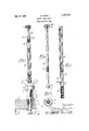
- Fig. 1 is a view in side elevation of the preferred form of my improved engine timing gauge.
- Fig. 2 is a horizontal sectional view through the same as taken on the line 2-2 of Fig. 1.
- Fig. 3 is a view partly in elevation and partly in section of a calibrated tube embodied in my improved gauge.
- Fig. i is a view in elevation of a piston engaging rod embodied in my improved gauge.
- 1 indicates a plug like member forming the means by which the gauge as a whole is operatively attached to an engine cylinder head 2, the associated Serial No. 176,935.
- said bottom end of the member is duplex so as'to be capable of use with either type of thread.
- On said body above'the threaded part l is a flange 6 which in engines having spark plug openings with standard threads, will engage the top of the cylinder head when properly screwed therein.
- the top end of saidv body is made hexagonal as at 7 to receive a wrench and above this heX- agonal part, saidv body is tapered to provide a reading edge 8.
- a tubular gauge rod 10 In the bore 9 of said member 1 is arranged a tubular gauge rod 10, the same so fitting the bore 9 as to be longitudinally movable therein, ⁇ as well as rotatable, but without lateral play between the two.
- the bottom end of said' gauge rod is interiorly threaded 76 as at 11 for a purpose tol appear later.
- On the exterior of said gauge rod is formed a plurality of equally spaced', longitudinally extending grooves 12412 which divide the gauge'rod into a pluralityvof faces 13-13- SU Each face is calibrated with suitable division or graduation marks as indicated at' 14, all starting from a common horizontal plane or line indicated at 15, which line is located a short distance above the termination of the t threads 11.
- a rod 16 which for convenience I have termed a piston engaging rod for reasons later to appear.
- Said rod which is of a length greater than ⁇ the calibrated tube, is of a diameter smaller than the same and at a point spaced a suitable distance above its bottoni end is provided with a length of thread 17 to engage the thread 11 of the tube.
- the bottom end of the rod has a radial flange 18 of' a diameter approximating the outside diameterof the tube and said flange terminates in a point 19.
- the top end 20 of said rod is reduced in diameter and has fixed thereto a knob 21 by which it is manipulated, the knob being fixed to said rod after its insertion into the tube.
- the piston stroke of a motor is notknown. Under such a condition, the said stroke must be first ascertained before the valve timing may be determined. To this end the piston is brought to the top of its stroke and the rod 16 is turned in the proper direction (the tube being held against rotation) to bring the common reading line into registration with the reading edge on the plug member. The piston is then moved to the bottom of the stroke, thus bringing one of the top most calibrations on the tube into registration with said reading edge which reading will of course correspond to the piston stroke. With the piston stroke thus known, the crank pin circle becomes known and it is an easy matter to set the same in the desired position for the opening and closing ⁇ of the valves, in the manner heretofore described.
- rlhe device as illustrated herein is for the n purpose of operation in the usual spark plug opening, but as is apparent it may so far as its principle is concerned also operate in such otherv holes in the cylinder where it is possible to engage the piston as described.
- the device is simple in construction and employs no springs or other delicate parts which can readily get out of order.
- lt is positive and accurate and is capable of easy manipulation. y
- a device ot the kind described comprising a supporting member adapted to be threaded into a hole in a cylinder head above a piston and having an opening therethrough, a gauge member longitudinally movable through. the opening in said member and having at least one set ot calibrations, thereon, said supporting member having a part with which said calibrations may be associated in the movement of the gauge meinber through said supporting member and a piston engaging rod disposed in said gauge member and of a length greater than 'the same so as to project beyond the ends thereof, said rod and gauge member having engaging parts perinittino' a relative longitudinal adjustment between them.
- a device of the kind described comprising a supporting member having an opening therethrough, a gauge member longitudinally movable through the opening in said supporting member and provided with a plurality of sets of calibrations thereon, graduated to indicate spaced angular positions on crank pin circles ot' diverent diameters, all of said sets otA calibrations beginning at a common line, ,Y ,tid supporting member having a part with which any set of calibrations may be associated in the movement ot the gauge member through the supporting member.
- a device oi the kind described comprisng a supporting member having an opening herethrough, a gauge member longitudinally movable through the opening in said supporting member and provided with a plurality of sets of calibrations thereon, graduated to indicate spaced angular positions on crank pin circles of ditlerent diameters, all of said sets oit calibrations beginning at a common line, said supporting member having a bevelled part, at its top end providing a reading edge with which any set ot' calibrations may be associated in the movement of the gauge member through the supporting member.
- a device of the kind described comprising' a tubular supporting member, a gauge tube longitudinally movable therethrough and having a plurality of faces each with a set of calibrations thereon dill'ering one from the other, but all starting at a common line, means providing a reading edge on said supporting member and with which any set of calibrations may be associated, and a piston engaging member carried by said gauge tube and having parts normally projecting beyond each end of the same, said gauge tube and piston engaging member having interengaging parts providing a relative longitudinal adjustmentbetween them.
- a device of the kind described comprising a tubular supporting member screw threaded at one end and tapered at its other end to form a reading edge, said member being ot a rectangular cross section between its ends for the application of a wrench, a gauge member movable longitudinally through said supporting member and longitudinally grooved to provide a plurality of iaces each ditlerently calibrated, said calibrations all starting from a common line, and a piston engaging member carried by the gauge tube, said gauge member and piston engaging member having interengaging parts providing a relative longitudinal adjustment between them.
- a device of the kind described comprising a tubular supporting member screw threaded at one end and tapered at its other end to torni a reading edge, said member being of a rectangular cross section between its ends for the application of a wrench, a gauge member movable longitudinally
Landscapes
- Physics & Mathematics (AREA)
- General Physics & Mathematics (AREA)
- A Measuring Device Byusing Mechanical Method (AREA)
Description
Dec. 3, 1929. c. MuzYN ENGINE TIMING GAUGE Filed man 21, 1921 Patented Dec. 3, 1929 STATES CLEMENS MUZYN, OF GARY, INDIANA ENGINE TIMING GAUGE Application filed March 21, 1927.
rIhis invention relates to improvements in engine timing gauges, and it consists of the matters hereinafter described and more fully pointed out in the appended claims. One of the objects of the present invention is to provide a gauge of this kind of simple construction whereby the opening and closw ing of the valves of an engine may be easily and accurately timed with respect to the posi tion of theV associated piston in its cylinder.
A further object of the invention is to provide a gauge of this kind which may be employed in connection with any one of a number of engines having piston strokes of different lengths and which may be easily manipulated for its intended purpose.
Still another object of the invention is to provide a gauge of this kind whereby the unknown piston stroke of an engine may be readily found out and the valves thereof timed in relation to said piston.
Still another object of the invention is to provide such a device which may be secured v into a vspark plug or similar opening for attachment to the cylinder of the engine, the valves of which it is desired to time with respect to the position of the piston.
These objects of the invention as wellas others together with the many advantages thereof, will more fully appear as I proceed with my specification.
In the drawings Fig. 1 is a view in side elevation of the preferred form of my improved engine timing gauge.
Fig. 2 is a horizontal sectional view through the same as taken on the line 2-2 of Fig. 1.
Fig. 3 is a view partly in elevation and partly in section of a calibrated tube embodied in my improved gauge.
Fig. i is a view in elevation of a piston engaging rod embodied in my improved gauge.
Referring now in detail to that embodiment of the invention illustrated in the accompanying drawing, 1 indicates a plug like member forming the means by which the gauge as a whole is operatively attached to an engine cylinder head 2, the associated Serial No. 176,935.
into a spark plug opening' in the cylinder head. As some engines employ metric threads and some standard threads in said opening, said bottom end of the member is duplex so as'to be capable of use with either type of thread. On said body above'the threaded part l is a flange 6 which in engines having spark plug openings with standard threads, will engage the top of the cylinder head when properly screwed therein. The top end of saidv body is made hexagonal as at 7 to receive a wrench and above this heX- agonal part, saidv body is tapered to provide a reading edge 8.
In the bore 9 of said member 1 is arranged a tubular gauge rod 10, the same so fitting the bore 9 as to be longitudinally movable therein,` as well as rotatable, but without lateral play between the two. The bottom end of said' gauge rod is interiorly threaded 76 as at 11 for a purpose tol appear later. On the exterior of said gauge rod is formed a plurality of equally spaced', longitudinally extending grooves 12412 which divide the gauge'rod into a pluralityvof faces 13-13- SU Each face is calibrated with suitable division or graduation marks as indicated at' 14, all starting from a common horizontal plane or line indicated at 15, which line is located a short distance above the termination of the t threads 11. As .engines of different makes usually employ piston strokes of dierent lengths, say from four inches up to live and one half inches, and which are recognized as standard, I have calibrated each face for a length corresponding to one of said standardized strokes and each stroke is designated at the top of the respective face by a numeral. It is pointed out that the calibrations do not indicate fractions of lineal' measurements J5 such as eighth yand quarter inches but indicate projections equal to vertical spacings, of divisions each measured off, ten degrees apart on the crank pin circle of engines of the respective strokes. Thus the calibrations 1w UIL are spaced closer together at the ends of each set of' calibrations and further apart midway between said ends as will be apparent. Furthermore the calibrations at the ends of each length are further calibrated to indicate divisions less than ten degrees on the crank pin circle.
In said calibrated tube is a rod 16 which for convenience I have termed a piston engaging rod for reasons later to appear. Said rod which is of a length greater than `the calibrated tube, is of a diameter smaller than the same and at a point spaced a suitable distance above its bottoni end is provided with a length of thread 17 to engage the thread 11 of the tube. The bottom end of the rod has a radial flange 18 of' a diameter approximating the outside diameterof the tube and said flange terminates in a point 19. The top end 20 of said rod is reduced in diameter and has fixed thereto a knob 21 by which it is manipulated, the knob being fixed to said rod after its insertion into the tube.
' Assume that the rod has been assembled in the tube and the tube has been inserted in the plug member 1 and it is desired to time the valves of an engine having a known piston stroke of sayfive inches for example. The plug member is screwed into the spark plug opening 5 in the cylinder head andthe engine is slowly turned over to bring the piston to the top of its stroke. When this position of the piston has been approximated the tube is moved downwardly through the plug member to bring the common line 15 of calibration into the plane of the reading edge 8. The tube is then held against rotation and the knob 21 on the rod is turned clockwise to feed the rod downwardly the point 19 vpenetrating such carbon deposit on the piston as may have accumulated thereon whereby it is felt when good positive engagement has been made with the piston. By slightly rocking the engine crank to which the piston is connected the rod and tube will rise and fall with the piston and if the common line 15 of calibration on the tube is raised above the reading edge, this will indicate that the tube is not as yet properly adjusted for a correct reading. The rod 16 is then turned counter clockwise until the common line 15 registers with the reading edge. lhen the angular position of the crank pin from top center is known for theproper opening of the inlet valves, the crank shaft is turned to move the piston downwardly that distance which is readily readable upwardly on that face on the gauge tube corresponding with the piston stroke. Likewise to determine when the inlet valve should close, the piston is first moved to the bottom of its stroke and then the top most line of calibration on said face for that piston stroke should register with the reading edge on the plug member. When the angular portion of the crank pin from bottom center is known for the proper' closing of the inlet valve it is only necessary to turn the crank shaft so that it moves upwardly until the proper calibration on said face (reading downwardly) registers with said reading edge. `With the known angular positions of the crank pin for the proper opening and closing of the exhaust valves, these positions may be determined in a similar manner of manipulation readily apparent.
Assume that the piston stroke of a motor is notknown. Under such a condition, the said stroke must be first ascertained before the valve timing may be determined. To this end the piston is brought to the top of its stroke and the rod 16 is turned in the proper direction (the tube being held against rotation) to bring the common reading line into registration with the reading edge on the plug member. The piston is then moved to the bottom of the stroke, thus bringing one of the top most calibrations on the tube into registration with said reading edge which reading will of course correspond to the piston stroke. With the piston stroke thus known, the crank pin circle becomes known and it is an easy matter to set the same in the desired position for the opening and closing` of the valves, in the manner heretofore described.
. rlhe device as illustrated herein is for the n purpose of operation in the usual spark plug opening, but as is apparent it may so far as its principle is concerned also operate in such otherv holes in the cylinder where it is possible to engage the piston as described.
The device is simple in construction and employs no springs or other delicate parts which can readily get out of order. lt is positive and accurate and is capable of easy manipulation. y
Vhile in describing my invention I have referred to many details of construction as well as form and arrangement of the parts thereof, the same is to be considered as by way of illustration only so that I do not wish to be limited thereto except as may be pointed out in the appended claims.
l claim as my invention:
l. A device ot the kind described comprising a supporting member adapted to be threaded into a hole in a cylinder head above a piston and having an opening therethrough, a gauge member longitudinally movable through. the opening in said member and having at least one set ot calibrations, thereon, said supporting member having a part with which said calibrations may be associated in the movement of the gauge meinber through said supporting member and a piston engaging rod disposed in said gauge member and of a length greater than 'the same so as to project beyond the ends thereof, said rod and gauge member having engaging parts perinittino' a relative longitudinal adjustment between them.
2. A device of the kind described comprising a supporting member having an opening therethrough, a gauge member longitudinally movable through the opening in said supporting member and provided with a plurality of sets of calibrations thereon, graduated to indicate spaced angular positions on crank pin circles ot' diiilerent diameters, all of said sets otA calibrations beginning at a common line, ,Y ,tid supporting member having a part with which any set of calibrations may be associated in the movement ot the gauge member through the supporting member.
3. A device oi the kind described comprisng a supporting member having an opening herethrough, a gauge member longitudinally movable through the opening in said supporting member and provided with a plurality of sets of calibrations thereon, graduated to indicate spaced angular positions on crank pin circles of ditlerent diameters, all of said sets oit calibrations beginning at a common line, said supporting member having a bevelled part, at its top end providing a reading edge with which any set ot' calibrations may be associated in the movement of the gauge member through the supporting member.
4. A device of the kind described comprising' a tubular supporting member, a gauge tube longitudinally movable therethrough and having a plurality of faces each with a set of calibrations thereon dill'ering one from the other, but all starting at a common line, means providing a reading edge on said supporting member and with which any set of calibrations may be associated, and a piston engaging member carried by said gauge tube and having parts normally projecting beyond each end of the same, said gauge tube and piston engaging member having interengaging parts providing a relative longitudinal adjustmentbetween them.
A device of the kind described comprising a tubular supporting member screw threaded at one end and tapered at its other end to form a reading edge, said member being ot a rectangular cross section between its ends for the application of a wrench, a gauge member movable longitudinally through said supporting member and longitudinally grooved to provide a plurality of iaces each ditlerently calibrated, said calibrations all starting from a common line, and a piston engaging member carried by the gauge tube, said gauge member and piston engaging member having interengaging parts providing a relative longitudinal adjustment between them.
G. A device of the kind described comprising a tubular supporting member screw threaded at one end and tapered at its other end to torni a reading edge, said member being of a rectangular cross section between its ends for the application of a wrench, a gauge member movable longitudinally
Priority Applications (1)
| Application Number | Priority Date | Filing Date | Title |
|---|---|---|---|
| US176935A US1737726A (en) | 1927-03-21 | 1927-03-21 | Engine timing gauge |
Applications Claiming Priority (1)
| Application Number | Priority Date | Filing Date | Title |
|---|---|---|---|
| US176935A US1737726A (en) | 1927-03-21 | 1927-03-21 | Engine timing gauge |
Publications (1)
| Publication Number | Publication Date |
|---|---|
| US1737726A true US1737726A (en) | 1929-12-03 |
Family
ID=22646502
Family Applications (1)
| Application Number | Title | Priority Date | Filing Date |
|---|---|---|---|
| US176935A Expired - Lifetime US1737726A (en) | 1927-03-21 | 1927-03-21 | Engine timing gauge |
Country Status (1)
| Country | Link |
|---|---|
| US (1) | US1737726A (en) |
Cited By (9)
| Publication number | Priority date | Publication date | Assignee | Title |
|---|---|---|---|---|
| US2426955A (en) * | 1943-07-13 | 1947-09-02 | Mary Mclaughlin Stroup | Indicator for airplane engines |
| US2514794A (en) * | 1947-10-07 | 1950-07-11 | Wesley G Prince | Flush pin gauge |
| US2619727A (en) * | 1950-03-21 | 1952-12-02 | Dill Mfg Co | Tire tread gauge |
| US2747289A (en) * | 1954-03-25 | 1956-05-29 | Lockheed Aircraft Corp | Engine indicator probe |
| US2829436A (en) * | 1955-12-23 | 1958-04-08 | Henry E Leinwebber | Centering gauge |
| US4252012A (en) * | 1979-06-04 | 1981-02-24 | Menasco Inc. | Shock absorber servicing tool |
| US4531295A (en) * | 1984-01-06 | 1985-07-30 | Saathoff Donald G | Timing tool |
| US5459940A (en) * | 1993-11-10 | 1995-10-24 | Mckenzie; James R. | Apparatus and process for determining top dead center of a piston and crank shaft in an internal combustion engine |
| USH1555H (en) * | 1993-11-08 | 1996-07-02 | Chrysler Corporation | Piston top dead center locating tool |
-
1927
- 1927-03-21 US US176935A patent/US1737726A/en not_active Expired - Lifetime
Cited By (9)
| Publication number | Priority date | Publication date | Assignee | Title |
|---|---|---|---|---|
| US2426955A (en) * | 1943-07-13 | 1947-09-02 | Mary Mclaughlin Stroup | Indicator for airplane engines |
| US2514794A (en) * | 1947-10-07 | 1950-07-11 | Wesley G Prince | Flush pin gauge |
| US2619727A (en) * | 1950-03-21 | 1952-12-02 | Dill Mfg Co | Tire tread gauge |
| US2747289A (en) * | 1954-03-25 | 1956-05-29 | Lockheed Aircraft Corp | Engine indicator probe |
| US2829436A (en) * | 1955-12-23 | 1958-04-08 | Henry E Leinwebber | Centering gauge |
| US4252012A (en) * | 1979-06-04 | 1981-02-24 | Menasco Inc. | Shock absorber servicing tool |
| US4531295A (en) * | 1984-01-06 | 1985-07-30 | Saathoff Donald G | Timing tool |
| USH1555H (en) * | 1993-11-08 | 1996-07-02 | Chrysler Corporation | Piston top dead center locating tool |
| US5459940A (en) * | 1993-11-10 | 1995-10-24 | Mckenzie; James R. | Apparatus and process for determining top dead center of a piston and crank shaft in an internal combustion engine |
Similar Documents
| Publication | Publication Date | Title |
|---|---|---|
| US1737726A (en) | Engine timing gauge | |
| US2739389A (en) | Concentricity gage | |
| US4517848A (en) | Apparatus for measuring forces | |
| US1877307A (en) | Tolerance zone on gauges | |
| US1464082A (en) | Valve-adjusting device | |
| US1879398A (en) | Gauge for sizing internal threads | |
| CN104165566A (en) | Detection apparatus of diameter and roundness of circular conical surface and detection method thereof | |
| US1758271A (en) | Engine-testing gauge | |
| US2663942A (en) | Instrument for measuring inside dimensions | |
| DE102014118661A1 (en) | Reciprocating internal combustion engine with sensors on a gas exchange valve | |
| US2665496A (en) | Internal comparative gauge | |
| US2826820A (en) | Hole gauges | |
| US1658994A (en) | Feeling-bolt-hole gauge | |
| US2855692A (en) | campbell | |
| US1465295A (en) | Caliper gauge | |
| DE1401237A1 (en) | Measuring device | |
| US2487677A (en) | Taper pipe thread gauge | |
| US1786325A (en) | Calipers | |
| US2649782A (en) | Cylinder bore taper gauge | |
| US1402139A (en) | Valve tester | |
| US1660469A (en) | Oversize attachment for adjustable internal gauges | |
| US2523469A (en) | Telescoping vernier gauge | |
| US1435428A (en) | Valve-stem-fitting device | |
| DE415971C (en) | Instrument for measuring hollow cylinders | |
| US2883758A (en) | Apparatus for measuring the size and symmetry of an opening formed in a work piece |