US1720249A - Fluid-pressure brake - Google Patents
Fluid-pressure brake Download PDFInfo
- Publication number
- US1720249A US1720249A US230984A US23098427A US1720249A US 1720249 A US1720249 A US 1720249A US 230984 A US230984 A US 230984A US 23098427 A US23098427 A US 23098427A US 1720249 A US1720249 A US 1720249A
- Authority
- US
- United States
- Prior art keywords
- fluid
- reservoir
- pressure
- cylinder
- release
- Prior art date
- Legal status (The legal status is an assumption and is not a legal conclusion. Google has not performed a legal analysis and makes no representation as to the accuracy of the status listed.)
- Expired - Lifetime
Links
- 239000012530 fluid Substances 0.000 description 78
- 230000001105 regulatory effect Effects 0.000 description 10
- 230000001276 controlling effect Effects 0.000 description 7
- 238000004891 communication Methods 0.000 description 4
- 208000036366 Sensation of pressure Diseases 0.000 description 2
- 230000006835 compression Effects 0.000 description 2
- 238000007906 compression Methods 0.000 description 2
- 230000003247 decreasing effect Effects 0.000 description 2
- 238000012856 packing Methods 0.000 description 2
- 241001527902 Aratus Species 0.000 description 1
- 230000004075 alteration Effects 0.000 description 1
- 230000006735 deficit Effects 0.000 description 1
- 230000001627 detrimental effect Effects 0.000 description 1
- 238000006073 displacement reaction Methods 0.000 description 1
- 239000010985 leather Substances 0.000 description 1
- 238000012423 maintenance Methods 0.000 description 1
- 238000000034 method Methods 0.000 description 1
- 238000012986 modification Methods 0.000 description 1
- 230000004048 modification Effects 0.000 description 1
Images
Classifications
-
- B—PERFORMING OPERATIONS; TRANSPORTING
- B60—VEHICLES IN GENERAL
- B60T—VEHICLE BRAKE CONTROL SYSTEMS OR PARTS THEREOF; BRAKE CONTROL SYSTEMS OR PARTS THEREOF, IN GENERAL; ARRANGEMENT OF BRAKING ELEMENTS ON VEHICLES IN GENERAL; PORTABLE DEVICES FOR PREVENTING UNWANTED MOVEMENT OF VEHICLES; VEHICLE MODIFICATIONS TO FACILITATE COOLING OF BRAKES
- B60T15/00—Construction arrangement, or operation of valves incorporated in power brake systems and not covered by groups B60T11/00 or B60T13/00
- B60T15/02—Application and release valves
- B60T15/18—Triple or other relay valves which allow step-wise application or release and which are actuated by brake-pipe pressure variation to connect brake cylinders or equivalent to compressed air or vacuum source or atmosphere
- B60T15/184—Railway control or brake valves
- B60T15/185—Railway control or brake valves with one slide valve
- B60T15/187—Railway control or brake valves with one slide valve with a slide valve for initiation and a second slide valve for control of the braking
Definitions
- This invention relates to fluid pressure braking apparatus and has for its object to provide arrangements for improving the operation of apparatus of this character and ensuring greater safety in operation.
- apparatus of the kind comprising a reservoir adapted to be connected to a brake cylinder by a distributing device during the first complete application of the brakes effected in a continuous or graduated manner.
- the initial energy constituted by a volume of fluid under pressure stored in a reservoir, is utilized in a cylinder placed in communication therewith, and as the reservoir and cylinder are connected together in a fluid tight manner, the equalization pressure corresponds to the maximum braking effort which can be obtained.
- the total mass of fluid contained in the reservoir and cylinder is equal to that initially contained beit'ore ell'ecting an application of the brakes, in the reservoir alone, and therefore at any instantwhile fluid is passing from the reservoir to the cylinder, at given pressure obtaining in the cylinder corresponds to a given pressure in the reservoir.
- the braking apparatus either losing in power by reason of the fact that during release the quantity at fluid which is released fr m the cylinder may be greater than that introduced into the reservoir, or gaining in power by reason ot the fact that a greater quantity of fluid than that released from the cylinder may be introduced into the reservoir during release.
- the storing on certain vehicles of an excess of power frequency causes a deficit of power on certain other vehicles, and always has a detrimental effect on the recharging and release of vehicles-at some distance from the source of supply, as in this case the driver cannot readily utilize the maximum recharging power at his disposal for fear of the abovementioned difiiculties.
- One of the objects of the resent invention is to provide'a evice which shall ensure when releasing, and consequently at any given moment, mutual correspondence between the pressures obtaining in the cylinder and in the reservoir, that is to say to arrange that during release the pressure obtaining in the reservoir shall be the same as that obtaining therein during braking, for each pressure obtaining in't-he cylinder.
- the device which it is therefore proposed to provide is so designed that if during the first application of the brakes effected the pressure obtaining in the cylinder is p when the pressure obtaining in the reservoir is P, then during release the same pressure p is attained in the cylinder when the pressure obtaining in the reservoir attains the value P above mentioned.
- the device constituting the main object of the invention will function to maintain the pressure-obtaining in the cylinder at a value p, by preventing, for the moment, the release of fluid from the cylinder.
- the device will prevent the further charging ot the reservoir whilst permitting the release of the cylinder, and then permit further charging of the reservoir when the pressures obtaining in the cylinder and reservoir respectively have attained values corresponding to the normal condition otthebrahing apparatus.
- the first device utilizes the simultaneous action of the two pressures considered above on the surfaces of a single piston and on the same side of the piston to balance an opposing spring a distributing device being operated by this piston for controlling the charging of the auxiliary reservoirand the release of fluid from the brake cylinder.
- the second device utilizes the simultaneous actionof-the two pressures considered above on two different PIStOHSEICUDg respectively pressure is decreasing with time, the corresponding piston is displaced under the action of its opposing spring.
- FIGS 3 and 4t illustratinganother constructional form of release regulating valve device.
- 1 is the brake cylinder, 2 :the auxiliary reservoir, 3 the piston ofthe triple valve, 4 the slide valve of the triple valve and 5 the slide valve of a double release regulating valve device.
- the cylinder '1 is connected to the triple valve-through a conduit 6and the triple valve is connected to the regulating valve device through a conduit 8 which serves for the passage of fluid under pressure from the train pipe 9 to recharge the reservoir 2.
- the usual teed groove has 7 been omitted, the air flowing to the reserlating device being connected to the auxiliary reservoir 2 througha conduit 15.
- this figure illustrates a device based on the principle of the maintaining constant of the sum of? the simultaneous actions of the pressures obtaining in the cylinder and reservoir respectively on a single piston adapted to actuate a slide valve.
- the body portion of the valve is constit-uted by two elements 16 and 18 and pipe the left face of which is subject in the cham ber 11 to the pressure obtaining in the auxil iary reservoir, and in the chamber 20 to the pressure obtaining in the brake cylinder through passage 21.
- the piston 19 is provided with two leather packings 22 and 23, and the body portion 16 is provided with a packing 24.
- the slide valve 5 is adapted to be operated by the piston 19 and has an aperture 10 therein which normally places the conduit 8 in communication withthe chamber 11, a cavity 12 placing the passages 7 and 13 in communication with one another.
- the piston 19 is subject on its right face to the effort exerted by one or more springs 25 the compression of which may be regulated by means of the element 18 secured by an element 26.
- the latter comprises a rod 47, which serves as an abutment for the pis ton 19 upon movement of the piston to the right.
- Figure 3 is illustrated a device based on the principle of the maintenance of a constant distance between two pistons which are subject simultaneously and respectively to the pressures obtaining in the reservoir and cylinder.
- It comprises a body portion 27 having adjustable elements 28 and 29 adapted to be secured by elements 30, and four pipe connections adapted to be connected to conduits 7, 8, 13 and 15, as described above.
- the body portion 27 moreover contains two pistons 31 and 32 controlling respec tively the superposed slide valves 34 and 33.
- the piston 31 is subject on its right face to the pressure obtaining in the auxiliary reservoir and consequently in the chamber 11, and is subject on its left face to the effort exerted by one or more springs 35.
- the piston 32 is subject on its left face, in the chamber 36 to the pressure obtaining in the brake cylinder which is transmitted to it through passages 6, 7 and 37, and is sub ject 011 its right face to the effort exerted by one or more springs 38, an element 39 separating the chambers 11 and 36.
- the slide valve 33 has three apertures therein, 40, which serves for the passage of fluid under pressure to recharge the reservoir, and 41 and 42 which permit of the passage of fluid from the cylinder to the exhaust element.
- the seat of the slide valve 33 has two grooves 43 and 44 therein, the first of which serves for charging the reservoir, and the second for releasing fluid under pressure from the cylinder when the two slide valves 33 and 34 have reached the end of their stroke to the left, this position corresponding to the position illustrated in Figure 4, where the auxiliary reservoir is being recharged and fluid being vented from the cylinder.
- the slide valve 34 has an aperture 10 therein connecting the aperture. 40 with the chamber 11 and a cavity 12 connecting apertures 41 and 42.
- the operation of the apparatus illustrated in Figures 1 and 2 is as follows Duringrelease the chamber 11 of the regulating valve is supplied with fluid under pressure from the train pipe 9 through the triple valve, through passage 8 and port 10.
- the passage 8 has a port 45 of predetermined size in. the body of the regulating valve, the cross sectional area of which port is sub stantially equal to that of the usual feed groove.
- the regulating valve is also supplied with fluid from the brake cylinder through conduit 7, this fluid flowing through passage 21 into chamber 20 and through cavity 12 into the pipe 13 to the exhaust element 14.
- the springs 25 are arranged to be controlled by means of'element 18 so that for example they permit equilibrium with the pressures of 0.800 kgs. in the cylinder and 4.600 kgs. in thereservoir and 3.500 kgs. in the cylinder and'3.500 kgs. in the reservoir.
- the aperture 10 and the cavity 12 are shown in the same plane whereas in practice these would be arranged in two parallel planes, the cavity 12 being elongated.
- the slide valve being displaced too much to the right, would uncover the port and maintain through cavity 12, communication between conduit 7 and 13, thus ensuring'the continuity of the two supplies of fluid as if theregulating valve did not exist.
- the device illustrated in Figures 3 and 4 is based on the principle of maintaining a constant distance between the pistons and operates as follows -During release the chamber 11 of the regulatingdevice is supplied through the triple valve with fluid from the train pipe through passage 8, and apertures 40 and 10, fluid from the cylinder being supplied through passages 7 and 37 to the chamber 36 so that the piston 31. is moved to the left, and piston 32 to the right.
- the opposing springs 35 and 38 are so regulated that the slide valves permit for example the two supplies of fluid under the following pressure conditions 0.800 kgs. in the cylinder and 4.600 kgs. in thereservoir and 3.500 kgs. in the cylinder and 3.500 kgs. in the reservoir.
- the distance between the pistons varies and theslide valves are subjected to a relative movement which causes the closure, through the slide valve 34 either of the aperture 40, or the aperture 42.
- the piston-31 is moved to the left more rapidly than the piston 32, and the upper slide valve 3 1 is moved to the left with respect to the lower slide valve 33, the aperture 40 being closed whilst the exhaust of fluid from the cylinder still takes place through cavity 12.
- the two slide valves are in their extreme positions to the left as shown in Figure 4 and fluid for the reservoir can flow freely through the conduit 8 on the one hand through aperture 10 and on the other hand through the cavity Moreover, the cylinder is connected permanently to the atmosphere through passage 7 and cavities 42'and 44: and through cavity 12 and aperture 41.
- Fluidpressure braking apparatus of the kind comprising an auxiliary reservoir or other source of fluid under pressure and a brake cylinder to which fluid is supplied and released in response to variations in pressure in the train pipe, comprising arrangements for maintaining strict proportionality between the pressures obtaining in the brake cylinder and reservoir respectively during operation for the purpose specified.
- Fluid pressure braking apparatus as claimed in claim 1, in which arrangements are provided for regulating the supply of fluid under pressure to the reservoir or other source of fluid pressure and the release of fluid under pressure from the brake cylinder in such a'manner that a predetermined pressure in the reservoir or other source of fluid pressure corresponds to a predetermined pressure in the brake cylinder at-any stage during the operation of the apparatus.
- Fluid pressure braking apparatus as claimed in claim 1 in which a valve device is provided comprising an abutment subject to the pressures obtaining in the brake cylinder and the reservoir or other source of fluid pressure and adapted to regulate the supply of fluid under pressure'to the reservoir and the release of fluid under pressure from the brake cylinder according to the predetermined proportionality between the pressures obtaining in the reservoir and brake cylinder.
- Fluid pressure braking apparatus as claimed in claim 1 in which a valve device is provided comprising two abutments, one subject to the pressure obtaining in the reservoir or other source of fluid pressure and the other subject to the pressure obtaining in the brake cylinder, the two abutmen'ts being adapted to cooperate with one another in such a manner as to regulate the supply of fluid under pressure to the reservoir and the release of fluid under pressure from the brake cylinder, substantially as and for the purpose specified.
- valve means for controlling the supply of fluid under pressure to the auxiliary reservoir, and the release of fluid from the brake cylinder in releasing the brakes, and means for maintaining the ratio bet-ween the auxiliary reservoir pressure and the brake cylinder pressure substantially constant in releasing the brakes.
- valve means for controlling the supply of fluid under pressure to the auxiliary reservoir and the release of fluid from the brake cylinder, and means for operating said valve means so that a substantially constant ratio is maintained between the auxiliary reservoir and brake cylinder pressures in the supply of fluid to the auxiliary reservoir and the release of fluid from the brake cylinder.
- valve means for controlling the supply of fluid under pressure to the auxil nowadaysy reservoir, and the release of fluid from the brake cylinder and movable in one direction to reduce the rate of flow to the auxiliary reservoir and in the opposite direction to restrict the exhaust of fluid from the brake cylinder, and a movable abutment subj ect to auxiliary reservoir and brake cylinder pressures for operating said valve means.
- valve means for controlling the supply of fluid under pressure to the auxiliary reservoir, and the release of fluid from the brake cylinder and movable in one direc tion to reduce the rate of flow to the auxiliary reservoir and in the opposite direction to restrict the exhaust of fluid from the brake cylinder, and means subject on one side to a constant pressure and on the opposite side to auxiliary reservoir and brake cylinder pressures for operating said valve means.
- valve means for controlling the supply of fluid under pressure to the auxil nowadaysy reservoir, and the release of fluid from the brake cylinder and movable in one direction to reduce the rate o'l flow to the auxiliary reservoir and in the opposite direction to restrict the exhaust of fluid from the brake cylinder, a spring, and a movable abutment subjectin one direction to auxiliary reservoir and brake cylinder pressures and in the opposite direction to the pressure of said spring for operating said valve means.
Landscapes
- Engineering & Computer Science (AREA)
- Transportation (AREA)
- Mechanical Engineering (AREA)
- Transmission Of Braking Force In Braking Systems (AREA)
Description
July 9, 1929.
J. GUlLLEMlN-TARAYRE FLUID PRES SURE BRAKE Filed Nov, 192'; 2 Sheets-Sheet INVE NTO R JEAN GUlLLEMlN-TARAYRE ATTORNEY y 9, 1929- J. GUlLLEMlN-TARAYRE .72 .249
FLUID PRES SURE BRAKE 2 Sheets-Sheet Filed Nov. 1927 INVENTOR E Y Mi w R O W w m MW y G Y as u Patented July 9, 1929.
UNITED STATES PATENT OFFICE.
JEAN 'GUILLEMIN-TARAYRE, OF VILLEMOMBLE, FRANCE, ASSIGNOR TO THE WEST- INGHOUSE AIR BRAKE COMPANY, OF WILMERDING, PENNSYLVANIA, A CORPORA- TION OF PENNSYLVANIA.
FLUID-PRESSURE BRAKE.
Application filed November 4, 1927, Serial No. 230,984, and in Great Britain November 10, 1926.
This invention relates to fluid pressure braking apparatus and has for its object to provide arrangements for improving the operation of apparatus of this character and ensuring greater safety in operation.
In some fluid pressure braking apparatus a certain quantity of energy which may be utilized, when required, to produce a more or less powerful braking effort, is stored.
In order however to ensure safety it is essential that the quantity or mass of stored fluid under pressure should be maintained the same at any. moment.
This condition is absolutely fulfilled by apparatus of the kind comprising a reservoir adapted to be connected to a brake cylinder by a distributing device during the first complete application of the brakes effected in a continuous or graduated manner. In practice, the initial energy constituted by a volume of fluid under pressure stored in a reservoir, is utilized in a cylinder placed in communication therewith, and as the reservoir and cylinder are connected together in a fluid tight manner, the equalization pressure corresponds to the maximum braking effort which can be obtained.
At any instant during braking, the total mass of fluid contained in the reservoir and cylinder is equal to that initially contained beit'ore ell'ecting an application of the brakes, in the reservoir alone, and therefore at any instantwhile fluid is passing from the reservoir to the cylinder, at given pressure obtaining in the cylinder corresponds to a given pressure in the reservoir.
In order that the braking apparatus shall at any instant possess its initial. mass or quantity of fluid, correspondence between the pressures obtaining in the reservoir and cylinder should be maintained under whatever conditions the braking apparatus is being employed.
It is a well known fact, in connection with long goods trains, that serious difiiculties are experienced, when running, in maintaining the quantity of stored energy, this being the case particularly on inclines.
Not one of the "arious known distributing devices overcomes this difliculty, the braking apparatus either losing in power by reason of the fact that during release the quantity at fluid which is released fr m the cylinder may be greater than that introduced into the reservoir, or gaining in power by reason ot the fact that a greater quantity of fluid than that released from the cylinder may be introduced into the reservoir during release.
It will readily be understood that the first alternative constitutes a serious danger, while serious disadvantages, the chief of which are as follows, arise as a consequence of the second alternative Firstly, the release of the brakes throughout the train is liable to be very unequal;
Secondly, an excess of power may result in braking efforts great enough to cause sliding of the wheels.
Thirdly, the storing on certain vehicles of an excess of power frequency causes a deficit of power on certain other vehicles, and always has a detrimental effect on the recharging and release of vehicles-at some distance from the source of supply, as in this case the driver cannot readily utilize the maximum recharging power at his disposal for fear of the abovementioned difiiculties.
One of the objects of the resent invention, therefore, is to provide'a evice which shall ensure when releasing, and consequently at any given moment, mutual correspondence between the pressures obtaining in the cylinder and in the reservoir, that is to say to arrange that during release the pressure obtaining in the reservoir shall be the same as that obtaining therein during braking, for each pressure obtaining in't-he cylinder.
The device which it is therefore proposed to provide is so designed that if during the first application of the brakes effected the pressure obtaining in the cylinder is p when the pressure obtaining in the reservoir is P, then during release the same pressure p is attained in the cylinder when the pressure obtaining in the reservoir attains the value P above mentioned.
If during release, the pressure in the res.- ervoir is maintained at the value P, on account of the train pipe not being recharged, the device constituting the main object of the invention will function to maintain the pressure-obtaining in the cylinder at a value p, by preventing, for the moment, the release of fluid from the cylinder.
Similarly, and this is one of the most importaat features of the device, if the pres-'- sure in :the reservoir should tend .to rise "by reason of a rapid recharging ot' the train pipe above the pressure P when the pressure obtaining in the cylinder has still a value greater than p, the device will prevent the further charging ot the reservoir whilst permitting the release of the cylinder, and then permit further charging of the reservoir when the pressures obtaining in the cylinder and reservoir respectively have attained values corresponding to the normal condition otthebrahing apparatus.
The objects whichit is proposed to achieve by the device constructed according to the invention, are
Firstly to render the braking apparatus capable of graduation by preventingthe release ot fluid from the cylinder when the pressure in the reservoirceases to rise.
Secondly to permit rapid recharging of the train pipe without fear of overcharging the vehicles at the head-0t a train and ensure on account of the possibility of rapid recharging and on account of the inability of the vehicles at the head of the train to store an excess of air,a morerapid propagzv tion of the release along the train and a more eflicient recharging of the rear vehicles.
Thirdly, to permit "the recharging otthe reservoirs without causing the release of the brakes of vehicles on which leakage from the cylinder may have abnormally decreased the pressure obtained therein.
Fourthly, in view of the fact that the re chargmg of the reservolrs isdependent'upon the release of fluid from the cylinders the release of fluid taking place in a uniform manner on all the vehicles of the train, to ensure, during a rapid release, a more uni- 'form charging of the reservoirs on the vehicles, independently of their position in the train.
Lastly to ensure absolutely that-the store of energy in the' 'brakingapparatus is inexhaustible.
Some methods of ensuring mutual corre spondence between the pressures obtaining simultaneously in the reservoir and the cylinder will now be indicated by way of example.
The devices described hereinafter are based on two different principles.
The first device utilizes the simultaneous action of the two pressures considered above on the surfaces of a single piston and on the same side of the piston to balance an opposing spring a distributing device being operated by this piston for controlling the charging of the auxiliary reservoirand the release of fluid from the brake cylinder.
As soon as equilibrium of pressure on the piston is destroyed, the distributing device is displaced and automatically cuts off the flow 0t fluid which has gained on the other. The second device utilizes the simultaneous actionof-the two pressures considered above on two different PIStOHSEICUDg respectively pressure is decreasing with time, the corresponding piston is displaced under the action of its opposing spring.
The displacements of the pistons being proportional to the variations-1n pressures acting thereon between two given instants,
the distances traversed by these pistons will also be proportional.
As long as the vflow'ot fluid is at a predetermined rate, the distance between-the pistons will remain constant, and'consequentl'y the distributing devices actuated by each of the pistons will not be. subjected to any relative movement.
hen this :is not the case differential movement of the two distribut ing devices is utilized to-cutofi' the flow ct fluid which is in advanee'ot the other.
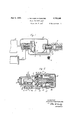
The invention will now be described, by way of example, with reference to the drawings accompanying :the provisional specilication, Figure 1 of these drawings being a general diagrammatic view of the braking ap )aratus.
Figures 3 and 4t illustratinganother constructional form of release regulating valve device.
Referring now to Figure 1, 1 is the brake cylinder, 2 :the auxiliary reservoir, 3 the piston ofthe triple valve, 4 the slide valve of the triple valve and 5 the slide valve of a double release regulating valve device.
The cylinder '1 is connected to the triple valve-through a conduit 6and the triple valve is connected to the regulating valve device through a conduit 8 which serves for the passage of fluid under pressure from the train pipe 9 to recharge the reservoir 2. In the present example the usual teed groove has 7 been omitted, the air flowing to the reserlating device being connected to the auxiliary reservoir 2 througha conduit 15.
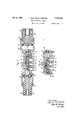
Referring now to Figure 2, this figure illustrates a device based on the principle of the maintaining constant of the sum of? the simultaneous actions of the pressures obtaining in the cylinder and reservoir respectively on a single piston adapted to actuate a slide valve. The body portion of the valve is constit-uted by two elements 16 and 18 and pipe the left face of which is subject in the cham ber 11 to the pressure obtaining in the auxil iary reservoir, and in the chamber 20 to the pressure obtaining in the brake cylinder through passage 21.
The piston 19 is provided with two leather packings 22 and 23, and the body portion 16 is provided with a packing 24.
The slide valve 5 is adapted to be operated by the piston 19 and has an aperture 10 therein which normally places the conduit 8 in communication withthe chamber 11, a cavity 12 placing the passages 7 and 13 in communication with one another.
The piston 19 is subject on its right face to the effort exerted by one or more springs 25 the compression of which may be regulated by means of the element 18 secured by an element 26. The latter comprises a rod 47, which serves as an abutment for the pis ton 19 upon movement of the piston to the right.
In Figure 3 is illustrated a device based on the principle of the maintenance of a constant distance between two pistons which are subject simultaneously and respectively to the pressures obtaining in the reservoir and cylinder.
It comprises a body portion 27 having adjustable elements 28 and 29 adapted to be secured by elements 30, and four pipe connections adapted to be connected to conduits 7, 8, 13 and 15, as described above.
The body portion 27 moreover contains two pistons 31 and 32 controlling respec tively the superposed slide valves 34 and 33. The piston 31 is subject on its right face to the pressure obtaining in the auxiliary reservoir and consequently in the chamber 11, and is subject on its left face to the effort exerted by one or more springs 35.
The piston 32 is subject on its left face, in the chamber 36 to the pressure obtaining in the brake cylinder which is transmitted to it through passages 6, 7 and 37, and is sub ject 011 its right face to the effort exerted by one or more springs 38, an element 39 separating the chambers 11 and 36. The slide valve 33 has three apertures therein, 40, which serves for the passage of fluid under pressure to recharge the reservoir, and 41 and 42 which permit of the passage of fluid from the cylinder to the exhaust element.
The seat of the slide valve 33 has two grooves 43 and 44 therein, the first of which serves for charging the reservoir, and the second for releasing fluid under pressure from the cylinder when the two slide valves 33 and 34 have reached the end of their stroke to the left, this position corresponding to the position illustrated in Figure 4, where the auxiliary reservoir is being recharged and fluid being vented from the cylinder.
The slide valve 34 has an aperture 10 therein connecting the aperture. 40 with the chamber 11 and a cavity 12 connecting apertures 41 and 42.
The operation of the apparatus illustrated in Figures 1 and 2 is as follows Duringrelease the chamber 11 of the regulating valve is supplied with fluid under pressure from the train pipe 9 through the triple valve, through passage 8 and port 10. The passage 8 has a port 45 of predetermined size in. the body of the regulating valve, the cross sectional area of which port is sub stantially equal to that of the usual feed groove.
The regulating valve is also supplied with fluid from the brake cylinder through conduit 7, this fluid flowing through passage 21 into chamber 20 and through cavity 12 into the pipe 13 to the exhaust element 14. As long as the piston 19 is in equilibrium, under the simultaneous pressures of the reservoir and of the cylinder, which, pressures obtain in the chambers 11 and 20 on the left face of the piston 19, and the pressures of the springs 25 which act on the right face of the piston, the continuity of the two supplies of fluid is maintained according to predetermined conditions.
As soon as the action of the total fluid pressures on the piston 19 however differs from the pressure exerted by the springs 25, the piston is moved and the slide valve interrupts one or other of the supplies of fluid.
In the case in which the recharging of the auxiliary reservoir tends to become too rapid, the slide valve moves to the right, and closes the port 45, the supply of fluid to the reservoir being interrupted, and the exhaust of fluid from the cylinder continuing until equilibrium is again established between the fluid pressures and the effort exerted by the springs 25 whereupon the slide valve will reassume its normal position.
If on the contrary, the supply of fluid to the reservoir should tend to become too slow, the piston will be moved to the left and will closethe port 46. The release of the brake will be momentarily arrested until the supply of fluid to the reservoir together with the pressure remaining in the cylinder, is suflicient to permit the piston to be moved to its normal position.
The springs 25 are arranged to be controlled by means of'element 18 so that for example they permit equilibrium with the pressures of 0.800 kgs. in the cylinder and 4.600 kgs. in thereservoir and 3.500 kgs. in the cylinder and'3.500 kgs. in the reservoir.
In Figure 2, for the sake of simplicity,
the aperture 10 and the cavity 12 are shown in the same plane whereas in practice these would be arranged in two parallel planes, the cavity 12 being elongated. In case of rupture or of too great compression of the spring 25, the slide valve being displaced too much to the right, would uncover the port and maintain through cavity 12, communication between conduit 7 and 13, thus ensuring'the continuity of the two supplies of fluid as if theregulating valve did not exist.
The device illustrated in Figures 3 and 4 is based on the principle of maintaining a constant distance between the pistons and operates as follows -During release the chamber 11 of the regulatingdevice is supplied through the triple valve with fluid from the train pipe through passage 8, and apertures 40 and 10, fluid from the cylinder being supplied through passages 7 and 37 to the chamber 36 so that the piston 31. is moved to the left, and piston 32 to the right.
The areas of the pistons being predetermined, the opposing springs 35 and 38 are so regulated that the slide valves permit for example the two supplies of fluid under the following pressure conditions 0.800 kgs. in the cylinder and 4.600 kgs. in thereservoir and 3.500 kgs. in the cylinder and 3.500 kgs. in the reservoir.
As long as the two supplies obey the predetermined law, the two pistons move to the left together with their slide valves, and
the two supplies are thus maintained, but
as'soon as the supplies tend to depart from the law, the distance between the pistons varies and theslide valves are subjected to a relative movement which causes the closure, through the slide valve 34 either of the aperture 40, or the aperture 42. For example, in case of too rapid recharging the piston-31 is moved to the left more rapidly than the piston 32, and the upper slide valve 3 1 is moved to the left with respect to the lower slide valve 33, the aperture 40 being closed whilst the exhaust of fluid from the cylinder still takes place through cavity 12.
On the contrary, in the case of insuflicient recharging, the piston 32 moves to the left more rapidly than the piston 31, and slide valve 33 slides under the slide valve 34, port 41 consequently being closed by slide valve 3.4, theexhaust of fluid from thecylinder thus being interrupted whilst the recharging of the reservoir continues.
When the reservoir is completely recharged, the two slide valves are in their extreme positions to the left as shown in Figure 4 and fluid for the reservoir can flow freely through the conduit 8 on the one hand through aperture 10 and on the other hand through the cavity Moreover, the cylinder is connected permanently to the atmosphere through passage 7 and cavities 42'and 44: and through cavity 12 and aperture 41.
The devices described above have been found most suitable for carrying the invention into practice, but it is evident that alterations and modifications may be made'therein, other elements being employed for the same purposes if required without exceeding the scope of the invention.
Having now described my invention, what I claim as new and desire to secure by Letters Patent, is
1. Fluidpressure braking apparatus of the kind comprising an auxiliary reservoir or other source of fluid under pressure and a brake cylinder to which fluid is supplied and released in response to variations in pressure in the train pipe, comprising arrangements for maintaining strict proportionality between the pressures obtaining in the brake cylinder and reservoir respectively during operation for the purpose specified.
2. Fluid pressure braking apparatus as claimed in claim 1, in which arrangements are provided for regulating the supply of fluid under pressure to the reservoir or other source of fluid pressure and the release of fluid under pressure from the brake cylinder in such a'manner that a predetermined pressure in the reservoir or other source of fluid pressure corresponds to a predetermined pressure in the brake cylinder at-any stage during the operation of the apparatus.
Fluid pressure braking apparatus as claimed in claim 1 in which a valve device is provided comprising an abutment subject to the pressures obtaining in the brake cylinder and the reservoir or other source of fluid pressure and adapted to regulate the supply of fluid under pressure'to the reservoir and the release of fluid under pressure from the brake cylinder according to the predetermined proportionality between the pressures obtaining in the reservoir and brake cylinder.
4. Fluid pressure braking apparatus as claimed in claim 1 in which a valve device is provided comprising two abutments, one subject to the pressure obtaining in the reservoir or other source of fluid pressure and the other subject to the pressure obtaining in the brake cylinder, the two abutmen'ts being adapted to cooperate with one another in such a manner as to regulate the supply of fluid under pressure to the reservoir and the release of fluid under pressure from the brake cylinder, substantially as and for the purpose specified.
5, In a fluid pressurebrake, the combination with a brake cylinder and auxiliary reservoir, of valve means for controlling the supply of fluid under pressure to the auxiliary reservoir, and the release of fluid from the brake cylinder in releasing the brakes, and means for maintaining the ratio bet-ween the auxiliary reservoir pressure and the brake cylinder pressure substantially constant in releasing the brakes.
6. In a fluid pressure brake, the combination with a brake cylinder and auxiliary reservoir, of valve means for controlling the supply of fluid under pressure to the auxiliary reservoir and the release of fluid from the brake cylinder, and means for operating said valve means so that a substantially constant ratio is maintained between the auxiliary reservoir and brake cylinder pressures in the supply of fluid to the auxiliary reservoir and the release of fluid from the brake cylinder.
7. In a fluid pressure brake, the combination with a brake cylinder and auxiliary reservoir, of valve means for controlling the supply of fluid under pressure to the auxil iary reservoir, and the release of fluid from the brake cylinder and movable in one direction to reduce the rate of flow to the auxiliary reservoir and in the opposite direction to restrict the exhaust of fluid from the brake cylinder, and a movable abutment subj ect to auxiliary reservoir and brake cylinder pressures for operating said valve means.
8. In a fluid pressure brake, the combination with abrake cylinder and auxiliary reservoir, of valve means for controlling the supply of fluid under pressure to the auxiliary reservoir, and the release of fluid from the brake cylinder and movable in one direc tion to reduce the rate of flow to the auxiliary reservoir and in the opposite direction to restrict the exhaust of fluid from the brake cylinder, and means subject on one side to a constant pressure and on the opposite side to auxiliary reservoir and brake cylinder pressures for operating said valve means.
9. In a fluid pressure brake, the combination with a brake cylinder and auxiliary reservoir, of valve means for controlling the supply of fluid under pressure to the auxil iary reservoir, and the release of fluid from the brake cylinder and movable in one direction to reduce the rate o'l flow to the auxiliary reservoir and in the opposite direction to restrict the exhaust of fluid from the brake cylinder, a spring, and a movable abutment subjectin one direction to auxiliary reservoir and brake cylinder pressures and in the opposite direction to the pressure of said spring for operating said valve means.
In testimony whereof I have hereunto set my hand.
JEAN GUILLEMIN TARAYRE.
Applications Claiming Priority (1)
| Application Number | Priority Date | Filing Date | Title |
|---|---|---|---|
| GB1720249X | 1926-11-10 |
Publications (1)
| Publication Number | Publication Date |
|---|---|
| US1720249A true US1720249A (en) | 1929-07-09 |
Family
ID=10889138
Family Applications (1)
| Application Number | Title | Priority Date | Filing Date |
|---|---|---|---|
| US230984A Expired - Lifetime US1720249A (en) | 1926-11-10 | 1927-11-04 | Fluid-pressure brake |
Country Status (1)
| Country | Link |
|---|---|
| US (1) | US1720249A (en) |
Cited By (2)
| Publication number | Priority date | Publication date | Assignee | Title |
|---|---|---|---|---|
| US2858169A (en) * | 1954-03-01 | 1958-10-28 | Westinghouse Air Brake Co | Fluid pressure brake apparatus |
| US20040231082A1 (en) * | 1999-06-11 | 2004-11-25 | Gavney James A. | Dentition cleaning device and system |
-
1927
- 1927-11-04 US US230984A patent/US1720249A/en not_active Expired - Lifetime
Cited By (2)
| Publication number | Priority date | Publication date | Assignee | Title |
|---|---|---|---|---|
| US2858169A (en) * | 1954-03-01 | 1958-10-28 | Westinghouse Air Brake Co | Fluid pressure brake apparatus |
| US20040231082A1 (en) * | 1999-06-11 | 2004-11-25 | Gavney James A. | Dentition cleaning device and system |
Similar Documents
| Publication | Publication Date | Title |
|---|---|---|
| US1720249A (en) | Fluid-pressure brake | |
| US3100553A (en) | Disc brakes for vehicles | |
| US2113649A (en) | Fluid pressure brake | |
| US2998284A (en) | Multiple-unit locomotive brake control equipment | |
| GB1217540A (en) | Improvements in or relating to hydrodynamic retarder systems for vehicles | |
| US1854722A (en) | Fluid pressure brake | |
| US1890087A (en) | Triple valve for automatic railway brakes | |
| US1986472A (en) | Fluid pressure brake | |
| US1478832A (en) | Air-brake apparatus | |
| US2821442A (en) | Fluid pressure brake apparatus | |
| US2273952A (en) | Brake release control means | |
| US1192960A (en) | Fluid-pressure brake. | |
| US2034288A (en) | Fluid pressure brake | |
| US2395170A (en) | Variable load brake | |
| GB1059180A (en) | Vehicle brake mechanism | |
| US1881209A (en) | Fluid pressure brake | |
| US2148769A (en) | Inertia controlled brake | |
| US1505540A (en) | Railway brake apparatus | |
| US1585774A (en) | Freight brake equipment | |
| US2115516A (en) | Fluid pressure brake | |
| US1601585A (en) | Triple valve for air-brake apparatus | |
| US2033460A (en) | Fluid pressure brake | |
| US555196A (en) | weng-er | |
| US2032119A (en) | Fluid pressure brake | |
| US1458370A (en) | Air-brake-control valve |