US1715399A - Method of transferring knitted fabrics and mechanism for this purpose - Google Patents
Method of transferring knitted fabrics and mechanism for this purpose Download PDFInfo
- Publication number
- US1715399A US1715399A US72483A US7248325A US1715399A US 1715399 A US1715399 A US 1715399A US 72483 A US72483 A US 72483A US 7248325 A US7248325 A US 7248325A US 1715399 A US1715399 A US 1715399A
- Authority
- US
- United States
- Prior art keywords
- transfer
- sheet
- machine
- cam
- ring
- Prior art date
- Legal status (The legal status is an assumption and is not a legal conclusion. Google has not performed a legal analysis and makes no representation as to the accuracy of the status listed.)
- Expired - Lifetime
Links
Images


Classifications
-
- D—TEXTILES; PAPER
- D04—BRAIDING; LACE-MAKING; KNITTING; TRIMMINGS; NON-WOVEN FABRICS
- D04B—KNITTING
- D04B9/00—Circular knitting machines with independently-movable needles
- D04B9/40—Circular knitting machines with independently-movable needles with provision for transfer of knitted goods from one machine to another
Definitions
- FIG. 1 A first figure.
- This invention is concerned with transfer the knitting eanisloodily with respect to the 5 of knitted fabric from the needles of a proneedle cylinder.
- - ducing machine to a transfer device capable Ancther'aimof inv invention is to utilize of placement in other machines adapted to the relative movemdnt between the needle 5 perform Subsequent operations upon the web cylinder and knitting cams-as well as other in furthering the manufacture of articles characteristic motions inherent to such standcc of knitted ware.
- One instance of the useard knitting machinesin performin cerfi'iliicss of transfer mechanism of the chartaiii useful phases of the transfer opera tion.
- acte referred to is in connection with seanifurther object of my invention is to at- I advantages, together with either latch or spring beard needles) to acothers which w- 1 appear from the detailed coinplish an intermediate step pie-requisite description hereinafter, in fabric transfer to the closure of the toe pocket of thestockmechanism liavingthe form of an attachment ing; that is to say, to transfer the pocketed capable of being applied to standard knittin tubular web to a split point ring capable of machines without requiring any alteratioil subsequent placement in a sewing machine of whatever in them, either with regard their the kind shown and described in my Patent construction, or their normal cycle of opera- No.
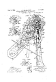
- Fig. l is a front 20 its opposite halves. l have accordingly hereview of a Scott type knitting machine inafter described my invention with referequipper with my improved transfer niecha- EIiCG: to this specific use, although, as will he nism. apparent from further explanation, it may Fig. be as readily employed with corresponding shown in advantages, in otherinstances involving or Fig. illis a plan view of tie organization is an elevationlooking toward the necessitating a transfer operation. left hand side of F so The main obgect of my invention is to enl is an elevation of tie left hand side able a transfer step of the character menof Fig. 1
- FIG. V is a partial front elevation of the inatically so as to dispense with the necessity machine showing the carrier for the transfer for dependence upon. special or skilled labor ring lowered in readiness for transfer of as has generally been the case heretofore; and fabric from the needle cylinder to the looping to secure this desideratuin by mechanism we points-of said ring.
- FIG. V1 is a fragmentary sectional view 30 knitting machines such as exemplified in the showing certain important details of the U. S. Patent of Robert Scott,hlo. 1,152,850, transfer ring cari'ie n ectional View,
- Figs. XII and XIII are plan sections, taken as respectively indicated by the arrows XII-XII and XIIIXIII in Fig. IX.
- Fig. XIV, Sheet'5 is a perspective view of a split transferring (generally similar to that shown and described in my Patent No. 1,348,195, August 3, 1920) conveniently em ployable in connection with the transfer mechanism of my present invention.
- Figs. XV, Sheet 6, an XVI, Sheet 8 are detail sectional views, taken as respectively indicated by the correspondingly identified arrows XVXV and XVI XVI in Fig.
- Fig. XVII is a fragmentary sectional view of the machine showing the manner in which the needle cylinder is elevated, to the position corresponding to that of Fig. XI, in the act of restoring the transfer ring to its original position in the carrier.
- Fig. XVIII is a sectional view, taken as indicated by the arrows XVIIIXVIII in Figs. IV and XXIIL'showing the means for moving the ejector to active position in readlness todisplace the finished fabric from the machine. u
- Fig. XIX is a partial development of the cam shell of themachine showing certain additional provisions facilitating transfer in accordance with my invention.
- Fig. XX is a partial plan sectional View of the cam shell with the additional adjuncts.
- Fig. XXI is a diagrammatic view showing the special picker control means illustrated in Fig. XX.
- Fig. XXII is a fragmentary view in plan of the means whereby the various instrumentalities of the transfer mechanism are controlled and timed.
- Fig. XXIII is an elevation of the as scmblage shown in Fig. XXII.
- Fig. XXIII, Sheet 4 is a fragmentary view of certain parts associated with the mechanism shown in Figs. XXII and XXIII, and as conveniently indicated by the arrows XXIII" appearing in theformer of said figures.
- Fig. XXIV is a development of one of the drums included in the control mechanism of Fig. XXII.
- Fig. XXV is an axial'sectional view of the drum aforesaid.
- Fig. XXVI is a plan sectional view of the drum. taken as indicated by the arrows. XXVI-XXVI in Fig. XXV.
- Fig. XXVII is a detail section, viewed in the direction of the arrows XXVII XXVII in Fig. XXVI.
- Figs. XXVIII and XXIX are fragmentary illustrations showing successive positions of the means for automatically shifting the drive belt to restart the machine after completion of the transfer operation.
- Fig. XXX is a plan view of the special sinker cam ring which I employfor the purposes of my invention.
- Figs. XXXI and XXXII, Sheet 1a are similar views with the' component parts in difierent positions.
- Figs. XXXIII and XXXIV, Sheet 13, as well as XXXV, Sheet 14, are Cllttglitll'lll ltltlc views showing the different positions of the sinker control cams respectively in accordance with Figs. XXX, XXXI' and XXXII.
- Fig. XXXVI, Sheet 14 is a detail sectional view taken as indicated by the arrows XXXIXXXVI in Fig. XXX, Sheet 13.
- Fig. XXXVI shows the normal cooperative relation between aneedle and the cor-. responding sinker during ordinary knittip g.
- Fig. XXXVIII' isa view similar to the preceding, but showing the fabric loop penctratcd by a point of the transfer ring and ready to becast fora-etainment by the latter.
- Fig. XXXIX shows'the relation of the needle sinker and point ring during loop casting.
- Fig. .XL is a similar view showing the re lation of the. same instrumentalities after loop casting.
- Fig. XIJI, Sheet 3 is a detail view of the mechanism for moving the latch guard ring of the machine to inoperative position.
- Fig. X'LII, Sheet 3 is a similar view showing the parts of the above mechanism in different positions. 7
- Fig. XLIII shows the details of the means for controlling the ejection of the finished stocking blank.
- Fig. XLIV, Sheet 4 is a view similar to the preceding, but with the parts in different positions. S
- Fig. XLV, Sheet 1 is a detail sectional view showing the details of the fabric ejector.
- Fig. XLVI, Sheet 15 shows a sectional View through the needle cylinder and associated parts of the type of knitting machine shown and-described in the llemphill patent hereinbefore referred to, and illustrating the manner in which certain phases of the transfer operation are effected on such a machine in accordance with my invention.
- Fig. XLVII is a fragmentary sectional view showing the manner. in which the needles are separated from the points of the transfer ring after the loops have been cast.
- Fig. XLVIII, Sheet 16 shows the special cam which I provide to shift the knitting earn support relative to the needles of the 'Hemphill machine incidental to fabric transfer;
- Fig. XLIX shows a partial diagrammatic development of the knitting cams of the Hemphill machine.
- the knitting machine therein depicted is generally similar to that shown and described in the Scott patent, supra.
- Its cylinder 1, which serves to sustain and guide the knitting needles N, is mounted for rotation in a bed plate 2 at the top of the frame 30f the machine.
- the cylinder 1 is rotated by gearing journalled on the frame 3, such gearing including a spur gear wheel 4 (Fig. HI) that meshes with a pinion 5 fast on the main drive shaft 6, the latter being equipped with the usual tight and loose pulleys 7, '8, respectively, as well as an intermediate pulley Qemployed to drive the cylinder 1 at reduced speed during fashioning of the heel and toe pockets i' tomary practice.
- Shifting of the drive belt accordance with cusbetwcen the pulleys 'Z', 8 and 9 is effected by a spring-pulled shipper 1O slidable on a rod 11 project from the frame 3, and under control a rotary cam 1 fast on a shaft 13, said shaft being intermittently rotated by lhe-pawling mechanism of the machine, and serving in turn.to drive, through internieshin gears 14 (Fig lV) a shaft 15 which carries the main pattern or cam drum 16.
- he sinkers as best shown in Figs. X and which cooperate with the needles N are mounted for radial sliding in an annulus 17 secured about the top of the needle cylinder 1.
- the needles N are actuated by a group of stitch cams 18 (Fig. XIX) with the assistance of lifting or elevating pickers 19 19 and a drop picker 20, that functions during the fashioning of the heel and toe pockets.
- the stitch cams 18 are-mounted on a segment 21 capable of being retracted laterally from the main section 0 of the cam shell for needle leveling,-
- a thrust rod 22, Fig. fill that is subject to a cam lug 23 on the main cam drum 16, precisely as in the Scott patent, su'pra.
- the main cam drum 16 of the machine controls selective activity of the interchangeable yarn feeds F igs. El and Ill) pivotally I mounted on the latch guard ring G, the latter being secured to a shaft 2 so as to be swingable upward, from the normal position to Ill to the raised position of Fig. V, when access must be had tothe needlecylinder l, in the present instance particularly to enable transferring.
- F or the purpose of lengthening or shortening the fabric loops as in fashioning the leg and ankle of the stocking the needle cylinder 1 is bodily movable with respect to the knitting ca-m shell C (see Fig.
- This fabric receiver 29 is sustained for vertical movement through guidance of its upper end in a depending flan goof the bed plate 2, and its lower end in an aligned an'nulus30, At one side, the fabric receiver 29 has a lug 31 adapted to be en aged by a projection32 of anarm 33, int1e path of a special log 34; on the main patterudrum-lth cured to t e llie mctionof the shaft 41 is in tur ransmitted, through a pinion 43 and gear ll, to a shaft 4* lso iournalled in the brtcket
- the gear carries av crank pin as which is coordinated by a link 46 with a rocker arm on another shaft 27 to the shorter extrern of which rocker arm is pivoted a pair Or wls 48, @n its upward strokes, the pawl l8 sucessively engages pins projecting from the gear 4.
- the companion pawl 49 successively picks pins 51, on the back of a gear 52 in direct mesh with the gear 4, and of the same pitch diameter.
- the pawl 48 would alone sutlice to step about the cylinder 1 for the purpose explained, I preferably employ the additional pawl 49 and the gear 52 to reduce the time interval neces sary for accomplishment of such progression, not only in order toenpedite transfer, but to shorten the periods of'idleness'of the machine between knitting of successive stocking blanks.
- the pawls 48, 49 are held inactive by laterally projecting pins'53 of a lever 54 fulcrumed, intermediate its ends at 55, to a suitable bracket attached to the frame 3.
- a lug 56 on the lever 54 is acted upon by circumferential projections 57, 57 of a rotary cam 58, secured to theshaft 13 with the belt shipper control cam 12, engagement between said lug 56 and cam 58 being at all times maintained by a spring 59 drawing upon the shorter end of the lever 54.
- a supplemental shifting means which includes a pawl 60 designed to engage peripheral projections til, 62 on the rotarv cam 12.
- the pawl 60 is pivoted to an arm 63 that oscillates freely on the shaft 15 of the main or pattern drum 16, and receives its rocking movement directly from the pawling mechanism ofthe machine.
- ()verthrow is swingable over members 68, 68,
- the transfer ring B (Fig. XIV), as pre viously stated, is of the kind adapted to be inserted in a sewing machine whereby the toe pocket of the stocking is subsequently closed, and to this end comprises the two shell parts or sections 66, 66 whereof the latter the former about hinges 67 to enable registry of its looping points I. with the corresponding points of the other section for doubling of the fabric loops preparatory to the sewing. It is to be understood that means (not shown) are provided for normally holding the parts 66, 66 locked, in the open position illustrated, to provide a complete circle of points P for receiving the fabric loops from the needles N.
- a stripper T Associated with the transfer device or ring R is a stripper T comprising a pair of semi-circular (respectively coordinated with the sections 66, 66) which together constitute an annulus having peripheral notches set apart by intervening projections that extend outward between the looping point-s P, see Fig. IX.
- the stripper members 68, 68 are each supported by a pair of rods 69 which are. slidable in inward flanges of the sections 66, '66 and joined beyond by arcuate plates 70, 7 0 accessible from within the ring R for actuation as hereinafter ex plained.
- the stripper T does not actually'function as such, but as an advance guard to insure, through the instrumentality of its peripheral notches, alignment of the needles N of the machine with the looping points P as the ring It is lowered onto the needle cylinder 1, as will be readily apparent from further description.
- the office of supporting the ring 11, during transfer is relegated to a carrier 71 shown as secured for swinging movement, to a shaft 72 journalled in an upstanding lug of a bracket 7 3, which is bolted to the bed plate 2 of the machine.
- the arm 74 of the carrier 71 terniinates in an annulus 7 5 with a .depending cylindric shell or head 76 capable of snugly receiving the transfer ring B after the manner shown in Fig. IX.
- Retainment of the transfer ring R in the head 76 is by meansas follows: As shown in Fig.
- the section 66 of the transfer ring R has, adjacent its top, a circumferential groove 7 7 which is approached through diametrically disposed notches 78 that are registrable with pins 79 projecting inwardly through slots 80 in the cylindric head 76.
- This bolt 81 is slidable in a guide 82and normally urged downward by a spring 83 so as to automatically slip into a peripheral notch 84; in the top edge of the transfer ring B when the latter is turned in being inserted into the head 76 of the carrier 71, as above explained.
- the carrier 71 is swung and the transfer ring R manipulated incidental to transfer, under control of the timing mechanism generally designated by the numeral 85.
- this timing mechanism 85 comprises a pair of cam drums 86, 87 that are intergeared as shown for simultaneous rotation in opposite directions, and supported in suspension by shafts S6, 87 dropped from the bracket 73.
- the cam drum 86 serves to control the locking of the needle cylinder 1 against rotation while the fabric transfer is being made, and, to this end, carries on its top a cam 88 that acts upon a vertically slidable rod 89 to effect swinging movement of a finger 90 which, in turn, imparts downward movement to a locking pin 91 adapted to enter an aperture in the bevel gear 27 carrying the needle cylinder 1, see Figs. V, VII and VII, said locking pin being ordinarily held raised by a helical compression spring 92, in an obvious manner.
- the cam drum 86 has a cam groove 93 for engaging a roller on the shorter arm of a bell crank 94, whereof the larger extremity has the form of a gear sector which meshes with the pinion 95 on the fulcrum shaft 72 of the carrier 71. Consequently, as the cam drum 86 is rotal ed, the transfer carrier 71 is swung from the position of Fig. I, to that of Fig. V. to lower the point ring R over the needle cylinder 1, and again to return it to the-original retracted position after the transfer has been effected, the lowered position of the carrier R being determined by engagementof a set screw 99", Fig. VI, on the tail 99 of arm 74, with a lug 73 on hearing bracket 73.
- lock "means comprising a bolt 96, Fig. V, that is slidable in a bearing 97, and whose lower end is acted upon by a cam block 98, Fig. XXII, on the top of cam drum 87, said bolt engaging behind a tail piece 99 on the carrier arm 74,
Description
Mm 4 l%& 1... 'N. D. WlLLEAMS 1,7 ,399
METHOD OF TRANSFERRING KNITTED FABRICS AND MECHANISM FOR THIS PURPOSE Filed Dec 1, 1925 l6 Sheets-Sheet l I 19.9 a, WITNESSES JNWNTOH:
. V Zmzz'sJIDVfiZZimizs, I
v I \J. TTORNEYS.
5mm i929 L. N. D. WILLEAMS 1 .399
' METHOD OF THANSFERRING KNITTED FABRICS AND MECHANISM FOR THIS PURPOSE FiledfDec. l, 1925 l6 Sheets-Sheet 2 INVENTOR;
dg a Li m max/mam BY I @;M@ j
@Ume 192%. L. MDQWILLIAMS ,71 ,3 9
METHOD OF TRANSF-ERRING KNITTED FABRICS AND MECHANISM FOR THIS PURPOSE Filed Dec. 1, 925" I 16 Sheet -sheet 5 II GELYZI.
' 42m WITNESSES l N V EN TOR: 55 Low zz/tfiwzzzmm,
I ATTORNEYS:
' Bfi [I 2225 ZZZ x 75125 Jun 4, Ri a 4190 law, WILUAMS 7 1.715 39% METHOD OF TRANSFERRING KNITTED FABRICs AND MECHANISM FOR THIS PURPOSE Filed Dec. l 1925 16 Sheet s5heet 5 my INVENTOR:
WITNESSES 01m MID. i/WLZiam,
' TTCRNEYS.
$11M WZQ L. N. D. wlLuAMs 97 93 9? METHOD CF TRANSFERRING KNITTED FABRICS AND MECHANISM FOR THIS PURPOSE 7 Filed Dec. 1, 1925 16 Sheets-Sheet 6* l li E1".
JETEZTQ p, N 31 WI A g L'eiimlfi fifi METHOD OF TRANSFERRING KNITTED FABRIC AND MECHANISM FOR THIS PURPOSE Filed D60; 1, 1925 l6 Sheets-Sheet 7 L-n p INVEZYTOR:
METHOD OF TRANSFERRLM KNITTE:
TRIS Filed Dec. 1, 1925 AND MECHANISM FOR HWENTOR:
June 9- L. N. D. WILLIAMS 1,715,399
METHOD OF TRANSFERRING KNITTED FABRICS AND MECHANISM FOR ,THIS PURPOSE Filed Dec. 1, 1925 4 l6 Sheets-Sheet 9 FIG WITNESSES v NlgVTligffR I v 011,15 z llama, K L
WELLIAMS METHOD OF TRAHSFERRING KNITTED FABRICS 15mm, i929. L AND MECHANISM FOR THIS PURPOS Filed Dec 1925 16 .She'eiQ-Sheet 1o INVENTOR." Lama nmwizzm a S 7 PK" 5- Mme 42, 1929 N.. D. WILLIAMS idlafi fig METHOD OF TRANSFERRING KNITTED FABRICS AND MECHANISM FOR THIS PURPOSE Filed DEG. l, 1925 l6 Sheets-Sheet ll WITNESSES INI ENTO I [YUM/11111612775,
TW By T Mid) mam ATTORNEYS.
AND MECHANISM FOR THIS PURPOSE L. N. D. METHOD OF TRANSFERRING KNITTED FABRIGS Filed Dec. 1, 1925 V Mama 4, 392%; wgL 1315.399 METHOD OF TRANSFERRING KNITTED FABRICS AND MECHANISM FOR THIS PURPOSE Filed Dec. 1, 1925 16 Sheets-Sheet l5 INVENTOR: Louz'a ND. Wiliama [466 K a BY June 4, 1929. L. N. D. WILLIAMS METHOD OF TRANSFERRING KNITTED FABRICS AND MECHANISM FOR THIS PURPOSE Filed Dec. 1, 1925 I 16 Sheets-Sheet l4 INVENTOR: Lama Mfl'WiZliam TTvnNEs s.
FIG.
June 4 1929; L. N. D. WILLIAMS 1,715,399. METHOD OF TRANSFERRING KNITTED FABRICS AND MECHANISM FOR THIS PURPOSE Filed 'Dec. 1, 1925 16 Sheets-Sheet y v INVENTOR:
i Lami' 11m. vmmm TTORNEYS.
D. WitLiAEvEES SFERRING KNITTED FABRICS v ISM FOR THIS PURPOSE -.i1ed Dec. 1, 1925 l6 Shet$-Sheet 16 INVENTOR: JJOLLZBJIZD Mum/m,
' WW ATTORNEYS.
ii) less hosiery knitting machines (employing tain the-foregoii s n g2 M seine 4-, lEQZtlD LOUIS N. D. WILLIAMS, OF OQONTZ, PENNSYLVANIA, ASSIGNOR TO SCOTT do W ILLIAMS, INCORPORATED, OF NEW YORK, N. L, A CORPORATION 033 MASSACHUSETTS.
METHOD or TRANSFERRING KNITT D nannies Ann mnonanrsia non tents rnnrosn.
Application tied member 1, 1925. Serial is. $2,483.
This inventionis concerned with transfer the knitting eanisloodily with respect to the 5 of knitted fabric from the needles of a proneedle cylinder.- ducing machine to a transfer device capable Ancther'aimof inv invention is to utilize of placement in other machines adapted to the relative movemdnt between the needle 5 perform Subsequent operations upon the web cylinder and knitting cams-as well as other in furthering the manufacture of articles characteristic motions inherent to such standcc of knitted ware. One instance of the useard knitting machinesin performin cerfi'iliicss of transfer mechanism of the chartaiii useful phases of the transfer opera tion. acte referred to, is in connection with seanifurther object of my invention is to at- I advantages, together with either latch or spring beard needles) to acothers which w- 1 appear from the detailed coinplish an intermediate step pie-requisite description hereinafter, in fabric transfer to the closure of the toe pocket of thestockmechanism liavingthe form of an attachment ing; that is to say, to transfer the pocketed capable of being applied to standard knittin tubular web to a split point ring capable of machines without requiring any alteratioil subsequent placement in a sewing machine of whatever in them, either with regard their the kind shown and described in my Patent construction, or their normal cycle of opera- No. 1,315,064, designed to automatically close tions incidental to the knitting of stocifings. "the toe pocket by uniting doubled loops of Referring tothe drawings, Fig. lis a front 20 its opposite halves. l have accordingly hereview of a Scott type knitting machine inafter described my invention with referequipper with my improved transfer niecha- EIiCG: to this specific use, although, as will he nism. apparent from further explanation, it may Fig. be as readily employed with corresponding shown in advantages, in otherinstances involving or Fig. illis a plan view of tie organization is an elevationlooking toward the necessitating a transfer operation. left hand side of F so The main obgect of my invention is to enl is an elevation of tie left hand side able a transfer step of the character menof Fig. 1
tioned to be accomplished entirely auto- Fig. V is a partial front elevation of the inatically so as to dispense with the necessity machine showing the carrier for the transfer for dependence upon. special or skilled labor ring lowered in readiness for transfer of as has generally been the case heretofore; and fabric from the needle cylinder to the looping to secure this desideratuin by mechanism we points-of said ring.
ful in connection with standard stocking Fig. V1 is a fragmentary sectional view 30 knitting machines such as exemplified in the showing certain important details of the U. S. Patent of Robert Scott,hlo. 1,152,850, transfer ring cari'ie n ectional View,
September 7, 1915, known in the trade as the Fig. is a partial p Scott and ll illiams machine, and of Joshua taken as indicated by the arrows WEE-Wi l.
D. Hemphill, N 0. 933,443, September 7, .1909, in Fig. V, showing the means-for temporarily 40 known as the Banner machine. These malocking the needle cylinder against rotation chines are typical of the kind now ordinarily used, and are generally similar in that they comprise a cylinder with needles and coindicated operative sinkers, means to rotatably oscillate F1 1 45 thecylinder durin the knitting of the stockr 1g.
is a fragme. sectional view ings, etc. Such machines, however, differ in showing the means provio a in the Scott me one respect, to-wit:in the Scott type mamachine to retract the stitch drawing cams chine the needle cylinder is bodily moved for needle leveling. with respect to the knitting cams for the purif; is a sectional view, ken as indi- 50 pose of fashioning the stocking-leg and ankle cated by the arrows .lX i g. Y, show through variation in the size of the loops ing the transfer ring carrier in position and drawn by the needles, while in the Hemphi'll with the ring poised above the needle cylinder type inachine, this same function is perof the machine in readiness to receive the formed in a converse manner, i. e., by moving fabric.
mai
taken at right angles to the plane of Fig. IX,
and showing successive positions of the various parts incidental to fabric transfer.
Figs. XII and XIII are plan sections, taken as respectively indicated by the arrows XII-XII and XIIIXIII in Fig. IX.
Fig. XIV, Sheet'5, is a perspective view of a split transferring (generally similar to that shown and described in my Patent No. 1,348,195, August 3, 1920) conveniently em ployable in connection with the transfer mechanism of my present invention.
Figs. XV, Sheet 6, an XVI, Sheet 8, are detail sectional views, taken as respectively indicated by the correspondingly identified arrows XVXV and XVI XVI in Fig.
XII. 1
Fig. XVII is a fragmentary sectional view of the machine showing the manner in which the needle cylinder is elevated, to the position corresponding to that of Fig. XI, in the act of restoring the transfer ring to its original position in the carrier.
Fig. XVIII is a sectional view, taken as indicated by the arrows XVIIIXVIII in Figs. IV and XXIIL'showing the means for moving the ejector to active position in readlness todisplace the finished fabric from the machine. u
Fig. XIX is a partial development of the cam shell of themachine showing certain additional provisions facilitating transfer in accordance with my invention.
Fig. XX is a partial plan sectional View of the cam shell with the additional adjuncts.
Fig. XXI is a diagrammatic view showing the special picker control means illustrated in Fig. XX.
I Fig. XXII is a fragmentary view in plan of the means whereby the various instrumentalities of the transfer mechanism are controlled and timed.
Fig. XXIII is an elevation of the as scmblage shown in Fig. XXII.
Fig. XXIII, Sheet 4, is a fragmentary view of certain parts associated with the mechanism shown in Figs. XXII and XXIII, and as conveniently indicated by the arrows XXIII" appearing in theformer of said figures.
Fig. XXIV is a development of one of the drums included in the control mechanism of Fig. XXII.
Fig. XXV is an axial'sectional view of the drum aforesaid.
Fig. XXVI is a plan sectional view of the drum. taken as indicated by the arrows. XXVI-XXVI in Fig. XXV.
Fig. XXVII is a detail section, viewed in the direction of the arrows XXVII XXVII in Fig. XXVI.
Figs. XXVIII and XXIX are fragmentary illustrations showing successive positions of the means for automatically shifting the drive belt to restart the machine after completion of the transfer operation.
Fig. XXX is a plan view of the special sinker cam ring which I employfor the purposes of my invention.
Figs. XXXI and XXXII, Sheet 1a, are similar views with the' component parts in difierent positions.
Figs. XXXIII and XXXIV, Sheet 13, as well as XXXV, Sheet 14, are Cllttglitll'lll ltltlc views showing the different positions of the sinker control cams respectively in accordance with Figs. XXX, XXXI' and XXXII.
Fig. XXXVI, Sheet 14:, is a detail sectional view taken as indicated by the arrows XXXIXXXVI in Fig. XXX, Sheet 13.
Fig. XXXVI]. shows the normal cooperative relation between aneedle and the cor-. responding sinker during ordinary knittip g.
Fig. XXXVIII'isa view similar to the preceding, but showing the fabric loop penctratcd by a point of the transfer ring and ready to becast fora-etainment by the latter.
Fig. XXXIX shows'the relation of the needle sinker and point ring during loop casting.
Fig. .XL is a similar view showing the re lation of the. same instrumentalities after loop casting.
Fig. XIJI, Sheet 3, is a detail view of the mechanism for moving the latch guard ring of the machine to inoperative position.
Fig. X'LII, Sheet 3, is a similar view showing the parts of the above mechanism in different positions. 7
Fig. XLIII, heet 4, shows the details of the means for controlling the ejection of the finished stocking blank.
Fig. XLIV, Sheet 4, is a view similar to the preceding, but with the parts in different positions. S
Fig. XLV, Sheet 1, is a detail sectional view showing the details of the fabric ejector.
Fig. XLVI, Sheet 15, shows a sectional View through the needle cylinder and associated parts of the type of knitting machine shown and-described in the llemphill patent hereinbefore referred to, and illustrating the manner in which certain phases of the transfer operation are effected on such a machine in accordance with my invention.-
Fig. XLVII is a fragmentary sectional view showing the manner. in which the needles are separated from the points of the transfer ring after the loops have been cast.
Fig. XLVIII, Sheet 16, shows the special cam which I provide to shift the knitting earn support relative to the needles of the 'Hemphill machine incidental to fabric transfer; and
Fig. XLIX shows a partial diagrammatic development of the knitting cams of the Hemphill machine.
With reference first to Figs. I, IV and VIII, the knitting machine therein depicted is generally similar to that shown and described in the Scott patent, supra. Its cylinder 1, which serves to sustain and guide the knitting needles N, is mounted for rotation in a bed plate 2 at the top of the frame 30f the machine. The cylinder 1 is rotated by gearing journalled on the frame 3, such gearing including a spur gear wheel 4 (Fig. HI) that meshes with a pinion 5 fast on the main drive shaft 6, the latter being equipped with the usual tight and loose pulleys 7, '8, respectively, as well as an intermediate pulley Qemployed to drive the cylinder 1 at reduced speed during fashioning of the heel and toe pockets i' tomary practice. Shifting of the drive belt accordance with cusbetwcen the pulleys 'Z', 8 and 9 is effected by a spring-pulled shipper 1O slidable on a rod 11 project from the frame 3, and under control a rotary cam 1 fast on a shaft 13, said shaft being intermittently rotated by lhe-pawling mechanism of the machine, and serving in turn.to drive, through internieshin gears 14 (Fig lV) a shaft 15 which carries the main pattern or cam drum 16. he sinkers as best shown in Figs. X and which cooperate with the needles N are mounted for radial sliding in an annulus 17 secured about the top of the needle cylinder 1. In knitting a stocking, the needles N are actuated by a group of stitch cams 18 (Fig. XIX) with the assistance of lifting or elevating pickers 19 19 and a drop picker 20, that functions during the fashioning of the heel and toe pockets. Z The stitch cams 18 are-mounted on a segment 21 capable of being retracted laterally from the main section 0 of the cam shell for needle leveling,-
a thrust rod 22, Fig. fill, that is subject to a cam lug 23 on the main cam drum 16, precisely as in the Scott patent, su'pra. The main cam drum 16 of the machine controls selective activity of the interchangeable yarn feeds F igs. El and Ill) pivotally I mounted on the latch guard ring G, the latter being secured to a shaft 2 so as to be swingable upward, from the normal position to Ill to the raised position of Fig. V, when access must be had tothe needlecylinder l, in the present instance particularly to enable transferring. F or the purpose of lengthening or shortening the fabric loops as in fashioning the leg and ankle of the stocking, the needle cylinder 1 is bodily movable with respect to the knitting ca-m shell C (see Fig. XVII) under guidance of an axial sleeve 26 integrally formed with the bevel gear 27, by whichsaid cylinder is coordinated with the drive mechansm of the machine. Vertical movement is imparted to the cylinder 1 by a pin 28, that extends through the gear 27 and engages the top of a tubular fabric receiver 29, beneath the bed plate 2. This fabric receiver 29 is sustained for vertical movement through guidance of its upper end in a depending flan goof the bed plate 2, and its lower end in an aligned an'nulus30, At one side, the fabric receiver 29 has a lug 31 adapted to be en aged by a projection32 of anarm 33, int1e path of a special log 34; on the main patterudrum-lth cured to t e llie mctionof the shaft 41 is in tur ransmitted, through a pinion 43 and gear ll, to a shaft 4* lso iournalled in the brtcket The gear carries av crank pin as which is coordinated by a link 46 with a rocker arm on another shaft 27 to the shorter extrern of which rocker arm is pivoted a pair Or wls 48, @n its upward strokes, the pawl l8 sucessively engages pins projecting from the gear 4. previously rcferred to, while during its idle downward strokes the companion pawl 49 successively picks pins 51, on the back of a gear 52 in direct mesh with the gear 4, and of the same pitch diameter. Although the pawl 48 would alone sutlice to step about the cylinder 1 for the purpose explained, I preferably employ the additional pawl 49 and the gear 52 to reduce the time interval neces sary for accomplishment of such progression, not only in order toenpedite transfer, but to shorten the periods of'idleness'of the machine between knitting of successive stocking blanks. During normal operation of the machine, the pawls 48, 49 are held inactive by laterally projecting pins'53 of a lever 54 fulcrumed, intermediate its ends at 55, to a suitable bracket attached to the frame 3. A lug 56 on the lever 54 is acted upon by circumferential projections 57, 57 of a rotary cam 58, secured to theshaft 13 with the belt shipper control cam 12, engagement between said lug 56 and cam 58 being at all times maintained by a spring 59 drawing upon the shorter end of the lever 54.
For the purposes of my invention, 1 cmploy, in addition to the standard equipment of the machine for progressing the cam shaft 18, a supplemental shifting means which includes a pawl 60 designed to engage peripheral projections til, 62 on the rotarv cam 12. The pawl 60 is pivoted to an arm 63 that oscillates freely on the shaft 15 of the main or pattern drum 16, and receives its rocking movement directly from the pawling mechanism ofthe machine. ()verthrow is swingable over members 68, 68,
64 designed to engage the tight pulley 7 dur-' 7 ing this time, said brake arm being fulcrumed forindependent movement on the protruding end of the shaft 15 and shifted to active position incidental to downward movement of the lever 54; in releasing the pawls d8, 49,
through engagement of one of the pins 53 with a leaf spring 65 projecting rearward from the brake arm shoe.
The transfer ring B (Fig. XIV), as pre viously stated, is of the kind adapted to be inserted in a sewing machine whereby the toe pocket of the stocking is subsequently closed, and to this end comprises the two shell parts or sections 66, 66 whereof the latter the former about hinges 67 to enable registry of its looping points I. with the corresponding points of the other section for doubling of the fabric loops preparatory to the sewing. It is to be understood that means (not shown) are provided for normally holding the parts 66, 66 locked, in the open position illustrated, to provide a complete circle of points P for receiving the fabric loops from the needles N. Associated with the transfer device or ring R is a stripper T comprising a pair of semi-circular (respectively coordinated with the sections 66, 66) which together constitute an annulus having peripheral notches set apart by intervening projections that extend outward between the looping point-s P, see Fig. IX. The stripper members 68, 68 are each supported by a pair of rods 69 which are. slidable in inward flanges of the sections 66, '66 and joined beyond by arcuate plates 70, 7 0 accessible from within the ring R for actuation as hereinafter ex plained. In the present connection, the stripper T does not actually'function as such, but as an advance guard to insure, through the instrumentality of its peripheral notches, alignment of the needles N of the machine with the looping points P as the ring It is lowered onto the needle cylinder 1, as will be readily apparent from further description.
The office of supporting the ring 11, during transfer is relegated to a carrier 71 shown as secured for swinging movement, to a shaft 72 journalled in an upstanding lug of a bracket 7 3, which is bolted to the bed plate 2 of the machine. The arm 74 of the carrier 71 terniinates in an annulus 7 5 with a .depending cylindric shell or head 76 capable of snugly receiving the transfer ring B after the manner shown in Fig. IX. Retainment of the transfer ring R in the head 76 is by meansas follows: As shown in Fig. XIV, the section 66 of the transfer ring R has, adjacent its top, a circumferential groove 7 7 which is approached through diametrically disposed notches 78 that are registrable with pins 79 projecting inwardly through slots 80 in the cylindric head 76. Thus, as the transfer ring R is inserted into the head 76 and slightly rotated incidentally to advance the diametrical notches 78 beyond the province of the pins 79, it is subsequently retained through cooperation of said pins with the groove 77 To prevent accidental release of the transfer ring It during downward movement of the carrier 71, as well as to insure its proper positioning for accurate registry of the looping points P with the needles N, I provide a locking means in the form of a bolt 81shown in Figs. XII, XIII and XV. This bolt 81 is slidable in a guide 82and normally urged downward by a spring 83 so as to automatically slip into a peripheral notch 84; in the top edge of the transfer ring B when the latter is turned in being inserted into the head 76 of the carrier 71, as above explained.
The carrier 71 is swung and the transfer ring R manipulated incidental to transfer, under control of the timing mechanism generally designated by the numeral 85. By reference to Figs. I, II, III, IV, XXII and XXIII it will be observed that this timing mechanism 85 comprises a pair of cam drums 86, 87 that are intergeared as shown for simultaneous rotation in opposite directions, and supported in suspension by shafts S6, 87 dropped from the bracket 73. Amongst other functions, the cam drum 86 serves to control the locking of the needle cylinder 1 against rotation while the fabric transfer is being made, and, to this end, carries on its top a cam 88 that acts upon a vertically slidable rod 89 to effect swinging movement of a finger 90 which, in turn, imparts downward movement to a locking pin 91 adapted to enter an aperture in the bevel gear 27 carrying the needle cylinder 1, see Figs. V, VII and VII, said locking pin being ordinarily held raised by a helical compression spring 92, in an obvious manner. The cam drum 86 has a cam groove 93 for engaging a roller on the shorter arm of a bell crank 94, whereof the larger extremity has the form of a gear sector which meshes with the pinion 95 on the fulcrum shaft 72 of the carrier 71. Consequently, as the cam drum 86 is rotal ed, the transfer carrier 71 is swung from the position of Fig. I, to that of Fig. V. to lower the point ring R over the needle cylinder 1, and again to return it to the-original retracted position after the transfer has been effected, the lowered position of the carrier R being determined by engagementof a set screw 99", Fig. VI, on the tail 99 of arm 74, with a lug 73 on hearing bracket 73. Displacement of the transfer carrier 7l,while lowered, is prevented by lock "means comprising a bolt 96, Fig. V, that is slidable in a bearing 97, and whose lower end is acted upon by a cam block 98, Fig. XXII, on the top of cam drum 87, said bolt engaging behind a tail piece 99 on the carrier arm 74,
Priority Applications (1)
| Application Number | Priority Date | Filing Date | Title |
|---|---|---|---|
| US72483A US1715399A (en) | 1925-12-01 | 1925-12-01 | Method of transferring knitted fabrics and mechanism for this purpose |
Applications Claiming Priority (1)
| Application Number | Priority Date | Filing Date | Title |
|---|---|---|---|
| US72483A US1715399A (en) | 1925-12-01 | 1925-12-01 | Method of transferring knitted fabrics and mechanism for this purpose |
Publications (1)
| Publication Number | Publication Date |
|---|---|
| US1715399A true US1715399A (en) | 1929-06-04 |
Family
ID=22107885
Family Applications (1)
| Application Number | Title | Priority Date | Filing Date |
|---|---|---|---|
| US72483A Expired - Lifetime US1715399A (en) | 1925-12-01 | 1925-12-01 | Method of transferring knitted fabrics and mechanism for this purpose |
Country Status (1)
| Country | Link |
|---|---|
| US (1) | US1715399A (en) |
Cited By (2)
| Publication number | Priority date | Publication date | Assignee | Title |
|---|---|---|---|---|
| US2515506A (en) * | 1946-02-05 | 1950-07-18 | Getaz James Louis | Method of and means for closing the toe of circular knit hose |
| US3306080A (en) * | 1963-10-22 | 1967-02-28 | Rossler Kurt | Device for removing and inverting hose-like knitted goods on circular knitting machines |
-
1925
- 1925-12-01 US US72483A patent/US1715399A/en not_active Expired - Lifetime
Cited By (2)
| Publication number | Priority date | Publication date | Assignee | Title |
|---|---|---|---|---|
| US2515506A (en) * | 1946-02-05 | 1950-07-18 | Getaz James Louis | Method of and means for closing the toe of circular knit hose |
| US3306080A (en) * | 1963-10-22 | 1967-02-28 | Rossler Kurt | Device for removing and inverting hose-like knitted goods on circular knitting machines |
Similar Documents
| Publication | Publication Date | Title |
|---|---|---|
| US2412248A (en) | Knitting method and machine | |
| US1715399A (en) | Method of transferring knitted fabrics and mechanism for this purpose | |
| US2727373A (en) | Knitting machine | |
| US2060020A (en) | Production of knitted fabrics | |
| US2385672A (en) | Machine for knitting hosiery | |
| US2073554A (en) | Automatic circular knitting machine | |
| US2933908A (en) | Selvage clipper | |
| US2305335A (en) | Straight bar knitting machine | |
| US1218073A (en) | Knitting-machine. | |
| US2301065A (en) | Circular knitting machine | |
| US2164337A (en) | Knitting machine and method of producing stockings thereon | |
| US1790632A (en) | weidner | |
| US2197706A (en) | Sinker operating means for knitting machines | |
| US3041860A (en) | Means for and method of operating the sinkers of knitting machines | |
| US2195183A (en) | Method of knitting seamless stockings and the like in stringwork | |
| US1282880A (en) | Knitting-machine. | |
| US2466536A (en) | Straight bar knitting machine | |
| US1529449A (en) | Circular-knitting machine for making lace tuck clocks | |
| US2191577A (en) | Method of and apparatus for knitting stockings | |
| US2811026A (en) | Circular knitting machine attachment | |
| US2173646A (en) | Knitting machine | |
| US2799149A (en) | Automatic transfer knitting machine and method | |
| US2221495A (en) | Straight bar knitting machine | |
| US928165A (en) | Knitting-machine. | |
| US1718327A (en) | Mechanism for transferring knitted webs |