US1715322A - Umbrella - Google Patents
Umbrella Download PDFInfo
- Publication number
- US1715322A US1715322A US279652A US27965228A US1715322A US 1715322 A US1715322 A US 1715322A US 279652 A US279652 A US 279652A US 27965228 A US27965228 A US 27965228A US 1715322 A US1715322 A US 1715322A
- Authority
- US
- United States
- Prior art keywords
- umbrella
- strips
- supporting
- apex
- members
- Prior art date
- Legal status (The legal status is an assumption and is not a legal conclusion. Google has not performed a legal analysis and makes no representation as to the accuracy of the status listed.)
- Expired - Lifetime
Links
Images
Classifications
-
- A—HUMAN NECESSITIES
- A45—HAND OR TRAVELLING ARTICLES
- A45B—WALKING STICKS; UMBRELLAS; LADIES' OR LIKE FANS
- A45B13/00—Umbrellas made of paper
Definitions
- the invention relates to temporary or emergency umbrellas, and especially to those having a body structure formed from self form-sustaining material, the object being to provide an umbrella of the type referred to with flap-like supporting means connected to. the umbrella to hang down freely in umbrella-supporting position and to be swung against the side when not "in use.
- the umbrella according to the invention comprises a conical, umbrella-like body structure formed from self form-sustaining material, and flap-like supporting means connected at one end to the underside thereof at a point removed from its apex.
- The-body structure is preferably formed from a single sheet of suitable material, by forming a slit inwardly from the edge and overlapping the material adjacent thereto to form a. conical structure, the overlapping edges being connected in any suitable manner.
- the supporting means comprise strips of semi-rigid material connected tothe under side of the structure at a point intermediate the edge and the apex, the strips being hinged at their inner connected ends so that they may hang freely in umbrella supporting position, or may be swung against the side when not in use to facilitate packing, sliippage, or storage.
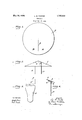
- Fig. 1 is a plan view of a sheet of material prepared for forming an umbrella
- Fig. 2 an elevation of an umbrella made from the sheet shown in Fig. 1
- Fig. 3 a detached supporting member shown to enlarged scale
- Fig. 4 anenlarged sectional View showing one manner of connecting a supporting member.
- the umbrella comprises a body portion 1, Fig. 2, and depending supporting members 2 connected thereto.
- the body is formed from a sheet 3 of a suitable semi-rigid material possessing sufficient rigidity to make it self form-sustaining when shaped, and sufficiently waterproofed, such as parafiined or calendered cardboard.
- a slit 4 Fig. 1 in a circular sheet 3, extendingfrom the edge substantially to the center, and lapping a portion A over the other edge portion B to form these members may vary, as may the manner of connecting them,
- the supporting means used is preferably formed from" strips of semi-rigid material, such as that used in'making the body structure. As shown in Fig. 2, it' is preferred to use two such members each connected at one end to the body structure at a point removed from its apex. The form and dimensions of provided adequate strength is secured, the preferred manner of connecting them being shown in Figs. 2 and 4.
- One'end of each strip 2 is bent to provide a foot or flange 5, which is glued or stitched to the underside of the body 1 at a pointintermediate theedge and the apex, and strips of adhesive material 6, such 'as gummed paper, are placed over the flange 5 andin the angle on the opposite side to further strengthen the joint. 5
- the supporting members hang freely in umbrella-supporting position in a manner similar to that of theusual umbrellas may be readily stacked for storage or shipment.
- the hinge-'action may, if de sired be furthered. by providing a line of weakness 7 in the-strip.
- two strips are used,they are preferably disposed diametrically opposite each-other at equal distances from the apex of body 1, the distance between them being such that when held over the head, the strips depend on each side thereof.
- the umbrella may be held in proper position by grasping one strip in each hand, or by grasping both in one I hand, in which case the strips will converge,
- the umbrellas are especially suitable for distribution to personscongregated outdoors, as at fairs, athletic events, or other gatherings, and advertising matter may be printed on them so that they provide an ex- 1 cellent and very'inexpensive publicity medium for free distribution, or for sale at a smallsum.
- An emergency umbrella fconsisting of a single sheet of semi-rigid material formed into a self form-sustaining umbrellaslike structure, and a pair of flapfli'ke' supporting members connected at their inner ends to the underside of said structure at points intermediate its edge and apex, said members hangi g r e yfro the r poin s not c n tion when in umbrella-supporting position and adapted to swing against the body of the umbrella when not in use.
- An emergency umbrella consisting of a single sheet of semi-rigid material formed into a self form-sustaining umbrella-like structure, and apair of diametrically opposed flap-like supporting members formed from strips of semi-rigid material connected at their inner ends to the underside of said structure at points'equally removed. from its apex, said members hanging freely, from their points of connection when in umbrella-sup porting position and adapted to swing against the body of the umbrella when not in use.
Description
May 28, 1929. B. FOSTER 1,715,322
UMBRELLA Filed May 22, 1928 Patented May 28, 1929.
[UNITED srA'r o v 1 "1,715,322 "NT. orriicr...
LEE B. ros rnn or PITTSBURGH, PENNSYLVANIA, AssmNoa'ro THE PARELLA con- PORATION, or PITTSBURGH, PENNSYLVANIA, A coaronn rron or PENNSYLVANIA.
UMBREL A.
Application fil ed May 22,
The invention relates to temporary or emergency umbrellas, and especially to those having a body structure formed from self form-sustaining material, the object being to provide an umbrella of the type referred to with flap-like supporting means connected to. the umbrella to hang down freely in umbrella-supporting position and to be swung against the side when not "in use. I
The umbrella according to the invention comprises a conical, umbrella-like body structure formed from self form-sustaining material, and flap-like supporting means connected at one end to the underside thereof at a point removed from its apex. The-body structure is preferably formed from a single sheet of suitable material, by forming a slit inwardly from the edge and overlapping the material adjacent thereto to form a. conical structure, the overlapping edges being connected in any suitable manner. In the preferred form the supporting means comprise strips of semi-rigid material connected tothe under side of the structure at a point intermediate the edge and the apex, the strips being hinged at their inner connected ends so that they may hang freely in umbrella supporting position, or may be swung against the side when not in use to facilitate packing, sliippage, or storage. Preferably two diametrically opposed strips areused.
The preferred embodiment of the invention is illustrated in the accompanying drawings, in which Fig. 1 is a plan view of a sheet of material prepared for forming an umbrella; Fig. 2 an elevation of an umbrella made from the sheet shown in Fig. 1; Fig. 3 a detached supporting member shown to enlarged scale; and Fig. 4 anenlarged sectional View showing one manner of connecting a supporting member.
Having reference to the drawings, the umbrella comprises a body portion 1, Fig. 2, and depending supporting members 2 connected thereto. The body is formed from a sheet 3 of a suitable semi-rigid material possessing sufficient rigidity to make it self form-sustaining when shaped, and sufficiently waterproofed, such as parafiined or calendered cardboard. Although the structure may be shaped in various ways, it is preferred to do this byforming a slit 4, Fig. 1, in a circular sheet 3, extendingfrom the edge substantially to the center, and lapping a portion A over the other edge portion B to form these members may vary, as may the manner of connecting them,
rigid umbrella handle, or they may be swung against the side when not in use so that the 1928. Serial No. 279,652.
a conical umbrella-like structure of the de sired proportions, such as that shown in Fig. 2. The overlapped material is connected together inany appropriate manner, as by stitching, gluing, and the like, and the struc ture thus formed requires no auxiliary reinforcement to maintain it in shape. V
The supporting means used is preferably formed from" strips of semi-rigid material, such as that used in'making the body structure. As shown in Fig. 2, it' is preferred to use two such members each connected at one end to the body structure at a point removed from its apex. The form and dimensions of provided adequate strength is secured, the preferred manner of connecting them being shown in Figs. 2 and 4. One'end of each strip 2 is bent to provide a foot or flange 5, which is glued or stitched to the underside of the body 1 at a pointintermediate theedge and the apex, and strips of adhesive material 6, such 'as gummed paper, are placed over the flange 5 andin the angle on the opposite side to further strengthen the joint. 5
By this construction the supporting members hang freely in umbrella-supporting position in a manner similar to that of theusual umbrellas may be readily stacked for storage or shipment. The hinge-'actionmay, if de sired be furthered. by providing a line of weakness 7 in the-strip. Where two strips are used,they are preferably disposed diametrically opposite each-other at equal distances from the apex of body 1, the distance between them being such that when held over the head, the strips depend on each side thereof. By this construction, .the umbrella may be held in proper position by grasping one strip in each hand, or by grasping both in one I hand, in which case the strips will converge,
and can beheld readily for adequate protec- 100 tion. The umbrellas are especially suitable for distribution to personscongregated outdoors, as at fairs, athletic events, or other gatherings, and advertising matter may be printed on them so that they provide an ex- 1 cellent and very'inexpensive publicity medium for free distribution, or for sale at a smallsum. v
According to the provisions of the patent statutes, I have explained theprinciple and 1,10
operation of myinvention, and have illustratedand described what Inow consider to represent its best embodiment. However, I desire to have it understood that, within the scope of. the appendedclaims, the invention may be practicedotherwise than as specifically illustrated and described.
position and adapted to swing against the body of the umbrella when not inuse.
2. An emergency umbrella fconsisting of a single sheet of semi-rigid material formed into a self form-sustaining umbrellaslike structure, and a pair of flapfli'ke' supporting members connected at their inner ends to the underside of said structure at points intermediate its edge and apex, said members hangi g r e yfro the r poin s not c n tion when in umbrella-supporting position and adapted to swing against the body of the umbrella when not in use.
' 3. An emergency umbrella consisting of a single sheet of semi-rigid material formed into a self form-sustaining umbrella-like structure, and apair of diametrically opposed flap-like supporting members formed from strips of semi-rigid material connected at their inner ends to the underside of said structure at points'equally removed. from its apex, said members hanging freely, from their points of connection when in umbrella-sup porting position and adapted to swing against the body of the umbrella when not in use.
In testimony whereof, I sign my name.
t LEE B. FOSTER.
Priority Applications (1)
| Application Number | Priority Date | Filing Date | Title |
|---|---|---|---|
| US279652A US1715322A (en) | 1928-05-22 | 1928-05-22 | Umbrella |
Applications Claiming Priority (1)
| Application Number | Priority Date | Filing Date | Title |
|---|---|---|---|
| US279652A US1715322A (en) | 1928-05-22 | 1928-05-22 | Umbrella |
Publications (1)
| Publication Number | Publication Date |
|---|---|
| US1715322A true US1715322A (en) | 1929-05-28 |
Family
ID=23069884
Family Applications (1)
| Application Number | Title | Priority Date | Filing Date |
|---|---|---|---|
| US279652A Expired - Lifetime US1715322A (en) | 1928-05-22 | 1928-05-22 | Umbrella |
Country Status (1)
| Country | Link |
|---|---|
| US (1) | US1715322A (en) |
Cited By (6)
| Publication number | Priority date | Publication date | Assignee | Title |
|---|---|---|---|---|
| US2552461A (en) * | 1948-12-15 | 1951-05-08 | Ruskin Samuel | Emergency umbrella and the like |
| US2605777A (en) * | 1946-02-14 | 1952-08-05 | Gustave S Berman | Sun shield and storm shield |
| US2672877A (en) * | 1950-02-03 | 1954-03-23 | Edward T Mcpartland | Disposable umbrella for emergency use |
| US3441038A (en) * | 1967-08-17 | 1969-04-29 | James Travis Mathews | Canopy assemblies |
| US4062369A (en) * | 1976-06-24 | 1977-12-13 | Terry Hermanson | Disposable rain and weather protector |
| US4215711A (en) * | 1978-12-28 | 1980-08-05 | Terry Hermanson | Disposable umbrella of paperboard material or the like |
-
1928
- 1928-05-22 US US279652A patent/US1715322A/en not_active Expired - Lifetime
Cited By (7)
| Publication number | Priority date | Publication date | Assignee | Title |
|---|---|---|---|---|
| US2605777A (en) * | 1946-02-14 | 1952-08-05 | Gustave S Berman | Sun shield and storm shield |
| US2552461A (en) * | 1948-12-15 | 1951-05-08 | Ruskin Samuel | Emergency umbrella and the like |
| US2672877A (en) * | 1950-02-03 | 1954-03-23 | Edward T Mcpartland | Disposable umbrella for emergency use |
| US3441038A (en) * | 1967-08-17 | 1969-04-29 | James Travis Mathews | Canopy assemblies |
| US4062369A (en) * | 1976-06-24 | 1977-12-13 | Terry Hermanson | Disposable rain and weather protector |
| US4114634A (en) * | 1976-06-24 | 1978-09-19 | Mr. Christmas Incorporated | Disposable rain and weather protector |
| US4215711A (en) * | 1978-12-28 | 1980-08-05 | Terry Hermanson | Disposable umbrella of paperboard material or the like |
Similar Documents
| Publication | Publication Date | Title |
|---|---|---|
| US1715322A (en) | Umbrella | |
| US3381889A (en) | Gift wrapping | |
| US621824A (en) | Satchel | |
| US3301452A (en) | Handle | |
| US715026A (en) | Collapsible box. | |
| US2163116A (en) | Luggage | |
| US2017168A (en) | Slipper-napkin for drinking receptacles | |
| US2386603A (en) | Garment hanger | |
| US560469A (en) | District of | |
| US1305199A (en) | Walter h | |
| US2346596A (en) | Fan mailing card folder | |
| US1490026A (en) | Vase | |
| US2992765A (en) | Collapsible trays | |
| US380364A (en) | surles | |
| US2902176A (en) | Display device | |
| US2067241A (en) | Star construction | |
| US632451A (en) | Collapsible box. | |
| US2950849A (en) | Box construction | |
| US2321883A (en) | Display box cover | |
| US1863997A (en) | Pliable fan | |
| US2239233A (en) | Folding box | |
| US203899A (en) | Improvement in paper boxes | |
| US2672877A (en) | Disposable umbrella for emergency use | |
| US1824677A (en) | Toy | |
| US1596091A (en) | Easel |