US1706363A - Passageway drive mechanism for articulated car units - Google Patents
Passageway drive mechanism for articulated car units Download PDFInfo
- Publication number
- US1706363A US1706363A US270918A US27091828A US1706363A US 1706363 A US1706363 A US 1706363A US 270918 A US270918 A US 270918A US 27091828 A US27091828 A US 27091828A US 1706363 A US1706363 A US 1706363A
- Authority
- US
- United States
- Prior art keywords
- passageway
- car
- drive mechanism
- pinion
- articulated
- Prior art date
- Legal status (The legal status is an assumption and is not a legal conclusion. Google has not performed a legal analysis and makes no representation as to the accuracy of the status listed.)
- Expired - Lifetime
Links
- 230000033001 locomotion Effects 0.000 description 8
- 238000007689 inspection Methods 0.000 description 2
- 229910000831 Steel Inorganic materials 0.000 description 1
- 230000004048 modification Effects 0.000 description 1
- 238000012986 modification Methods 0.000 description 1
- 239000010959 steel Substances 0.000 description 1
Images

Classifications
-
- B—PERFORMING OPERATIONS; TRANSPORTING
- B61—RAILWAYS
- B61D—BODY DETAILS OR KINDS OF RAILWAY VEHICLES
- B61D17/00—Construction details of vehicle bodies
- B61D17/04—Construction details of vehicle bodies with bodies of metal; with composite, e.g. metal and wood body structures
- B61D17/20—Communication passages between coaches; Adaptation of coach ends therefor
Definitions
- ALFRED 1 Hanson, OFKBELLEV'UE, PENNSYLVANIA, ASSIGNOR TO ranssnn STEEL ir En STATES'PRATENT- OFSFI-CE. f
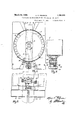
- Fig. 1 is a plan view or aportion oil. an articulated car unit showing the relation of the passageway member to the ends .of the two adjacent car bodies and the passageway drive mechanism;
- Fig. 2 is an elevation taken along the lines 22 of Fig. 1;
- Fig. 3 is an enlarged view of a portion of the passageway member and the passageway drive mechanism taken along the lines 33 of Fig. '1;
- Fig. 4 is a plan view of a portion of an'articulated car unit and shows a modi- 'fication of my invention;
- Fig. 5 is an.elevation taken along the lines 5-5 of Fig. 4;
- Fig. 6 is an enlarged view taken along the lines 6-6 of Fig. 5.
- reference character 1 indicates an articulated car unit comprising bodies 2 and 3 supported by means of bearings 4 on-a common truck (not shown).
- a passageway member 5 is pivotally supported between and extends into the two adjacent car bodies 2 and 3, the pivotal support'for this passageway member comprising a bearing member 6 contained on a bridge member 7 which is supported by any suitable means on the common truck.
- the bridge member 7 is broken away at one end to more clearly show the invention, but it is to be understood that the portion broken away is similar in all respects to the opposite end which is shown.
- the passageway member 1928 Serial No. 270,918.
- openings 8 and 9' which communicate wlth slmilar openings in the car bodies 2 and 3, and when the passageway member openings coincide with the openings in the car v body, a free and uninterrupted passage is provided to permit the passengers to move fromone car to the other.
- ahousing member 10' which contains and supports a pinion member 11 secured to the pin 12 which is freely rotatable in the housing.
- arms 14: and. 15 Attached to each one of the adjacent car bodies by means of brackets 13 are arms 14: and. 15 which are gear segments.
- the pinion'memher 11 is composed of two segmental pinions 16 and 17 which have teeth on only a portion of their periphery and are securely attached to the pin'12 by means of a key and are thus made to revolve as a unit.
- the arm 15 attached to the car body 2 is rotatably mounted in the bracket 13 and passes through an opening in the housing member 10 to engage the upper pinion segment 16 and the arm 14 secured to the body 3 is similarly mounted and passes through the housing to engage the lower pinion segment 17 7
- the articulated car unit is moving along a straight portion of the track and the adjacent ends of the adjacent car bodies passage for use of the passengers when moving from one car to the other.
- the articulated car unit When, however, the articulated car unit enters a curved portion of a track, and one of .the bodies is rounding the curve while the other car body is still on the straight portion of the track, the turning car body will move the arm attached to it either towards or away from the adjacent car body depending' on the direction of the turning.
- the moving arm in contact with one of the pinion segments of the pinion 11 will cause the pinion 11 to rotate and move along the non-moving arm secured to the other car body, this movement of the opinion will carry the passageway member along with it causing the passageway member to rotate in its pivotal support '6.
- the pitch diameter of the gear segments composing the arms is larger than the pitch diameter of the pinion segments attached to the passageway member and the turning off the passageway member will thus be proportionately less than the angle through which the turning car body moves.
- the openings 8 and 9 of the passageway member will proportion the movement of the opening in the one car body 3 between the two car bodies and maintain a free and uninterrupted passageway between them.
- both car bodies are traversing the curved portion of the track, and both car bodies are simultaneously displaced a like amount from the position they had to each other on a straight portion of the track, the
- body Wlll either move toward or away :trom
- a passageway member In an articulated car unit, a passageway member, a passageway drive mechanism, said mechanism comprising members mounted on the ends of the adjacent car bodies and rotatable longitudinally of the passageway member and engaging a member rotatably mounted on the passageway member.
- a passageway member In an articulated car unit, a passageway member, a passageway drive mechanism, said mechanism comprising members mounted on the ends of the car bodies adjacent the passageway member and engaging a pinion member mounted on the side of the'passageway member.
- a hollow cylindrical passageway member pivotally supported between and extending into the adjacent ends of the adjacent car bodies, a
Landscapes
- Engineering & Computer Science (AREA)
- Life Sciences & Earth Sciences (AREA)
- Wood Science & Technology (AREA)
- Mechanical Engineering (AREA)
- Vehicle Cleaning, Maintenance, Repair, Refitting, And Outriggers (AREA)
Description
A. K. PEHRSON March 19, 1929.
PASSAGEWAY DRIVE MECHANISM FOR ARTICULATED CAR UNITS Filed April 18, 1928 2 Sheets-Sheet March 19, 1929. A. K. PEHRSON 1,706,363
PASSAGEWAY DRIVE MECHANISM FOR ARTICULATED GAR UNITS Filed April 18, 1928 2 Sheets-Sheet 2 AZllENTOR Patented Mar. 19, 1929.
ALFRED 1:. Hanson, OFKBELLEV'UE, PENNSYLVANIA, ASSIGNOR TO ranssnn STEEL ir En STATES'PRATENT- OFSFI-CE. f
GAR COMPANY, OF PITTSBURGH, PENNSYLVANIA, A CORPORATION OF NEW JERSEY.
PASSAGEWAY DRIVE MEOHANISM FOR ARTIOULATED GAR ULTITS.
Application filed April is,
" adjacent car bodies.
Another ob ect of my invention being to provide rack and gear means for controlling the movements of the passageway member by movements of the car bodies.
Referring now to the drawings, Fig. 1 is a plan view or aportion oil. an articulated car unit showing the relation of the passageway member to the ends .of the two adjacent car bodies and the passageway drive mechanism; Fig. 2 is an elevation taken along the lines 22 of Fig. 1; Fig. 3 is an enlarged view of a portion of the passageway member and the passageway drive mechanism taken along the lines 33 of Fig. '1; Fig. 4 is a plan view of a portion of an'articulated car unit and shows a modi- 'fication of my invention; Fig. 5 is an.elevation taken along the lines 5-5 of Fig. 4; Fig. 6 is an enlarged view taken along the lines 6-6 of Fig. 5. v
Referring now in detail to the drawings where like reference characters refer to like parts, reference character 1 indicates an articulated car unit comprising bodies 2 and 3 supported by means of bearings 4 on-a common truck (not shown). A passageway member 5 is pivotally supported between and extends into the two adjacent car bodies 2 and 3, the pivotal support'for this passageway member comprising a bearing member 6 contained on a bridge member 7 which is supported by any suitable means on the common truck. InFig. 1 the bridge member 7 is broken away at one end to more clearly show the invention, but it is to be understood that the portion broken away is similar in all respects to the opposite end which is shown. The passageway member 1928. Serial No. 270,918.
5 has openings 8 and 9'which communicate wlth slmilar openings in the car bodies 2 and 3, and when the passageway member openings coincide with the openings in the car v body, a free and uninterrupted passage is provided to permit the passengers to move fromone car to the other. 'At one side of the passageway member is ahousing member 10' which contains and supports a pinion member 11 secured to the pin 12 which is freely rotatable in the housing. Attached to each one of the adjacent car bodies by means of brackets 13 are arms 14: and. 15 which are gear segments. The pinion'memher 11 is composed of two segmental pinions 16 and 17 which have teeth on only a portion of their periphery and are securely attached to the pin'12 by means of a key and are thus made to revolve as a unit. The arm 15 attached to the car body 2 is rotatably mounted in the bracket 13 and passes through an opening in the housing member 10 to engage the upper pinion segment 16 and the arm 14 secured to the body 3 is similarly mounted and passes through the housing to engage the lower pinion segment 17 7 When the articulated car unit is moving along a straight portion of the track and the adjacent ends of the adjacent car bodies passage for use of the passengers when moving from one car to the other.
When, however, the articulated car unit enters a curved portion of a track, and one of .the bodies is rounding the curve while the other car body is still on the straight portion of the track, the turning car body will move the arm attached to it either towards or away from the adjacent car body depending' on the direction of the turning. When such a condition exists the moving arm in contact with one of the pinion segments of the pinion 11 will cause the pinion 11 to rotate and move along the non-moving arm secured to the other car body, this movement of the opinion will carry the passageway member along with it causing the passageway member to rotate in its pivotal support '6. i As will be seen by an inspection of the drawings, the pitch diameter of the gear segments composing the arms is larger than the pitch diameter of the pinion segments attached to the passageway member and the turning off the passageway member will thus be proportionately less than the angle through which the turning car body moves. In this manner the openings 8 and 9 of the passageway member will proportion the movement of the opening in the one car body 3 between the two car bodies and maintain a free and uninterrupted passageway between them.
lVhen both car bodies are traversing the curved portion of the track, and both car bodies are simultaneously displaced a like amount from the position they had to each other on a straight portion of the track, the
arms attached to the ends of the turning car. body Wlll either move toward or away :trom
each other at a constant rate and the subsequent turning of the pinion 11 in its housing will serve to maintain the passageway member so as to again proportion the move ment between the two car bodies and maintain a free and uninterrupted passageway between them.
From the foregoing description and inspection of the drawings it will be readily apparent how the passageway member will operate regardless of the movement of onev adjacent car body relative to the other.
In the modification of my invention, as shown by Figs. 4, 5 and 6, the spur pinion segments are displaced by a beveledpinion and the arms attached to the car bodies are placed one above the other in their engagement with the pinion and the subsequent movements of the passageway member as caused by the movement of the adjacent ends of theadjacent car bodies is similar to that previously described.
Having thus described the invention what I claim asnew and desire to secure by Letters Patent is:
1. In an articulated car unit, a passageway member, a passageway drive mechanism, said mechanism comprising members mounted on the ends of the adjacent car bodies and rotatable longitudinally of the passageway member and engaging a member rotatably mounted on the passageway member. v p
2. In an articulated car unit, a passageway member, a passageway drive mechanism, said mechanism comprising members mounted on the ends of the car bodies adjacent the passageway member and engaging a pinion member mounted on the side of the'passageway member.
3. The combination in an articulated car unit of adjacent ends of adjacent car bodies supported on a common truck, a passageway member pivotally supported between and extending into sald bod1es,rotatably mounted gear segments on the car bodies engaging a pinion member mounted on the passageway member.
The combination in an articulated car unit of a passageway member pivotally supported between and extending into the ad jacent car bodies and a passageway drive mechanism, said. mechanism comprisinga rack pivotally mounted on each of the. ad jacent ends of adjacent car bodies engaging a bevel pinion member mounted on the side of said passageway member.
5. In an articulated ear unit, a hollow cylindrical passageway member pivotally supported between and extending into the adjacent ends of the adjacent car bodies, a
passageway drive mechanism, said mecha' bodies engaging the rotatably mounted member on the passageway member, and means on said passageway for maintaining the ro tatably mounted body members in contact with the member mounted on the passage way member. i V
In testimony whereof I afiix my signature.
ALFRED K. PEHR SON.
Priority Applications (1)
| Application Number | Priority Date | Filing Date | Title |
|---|---|---|---|
| US270918A US1706363A (en) | 1928-04-18 | 1928-04-18 | Passageway drive mechanism for articulated car units |
Applications Claiming Priority (1)
| Application Number | Priority Date | Filing Date | Title |
|---|---|---|---|
| US270918A US1706363A (en) | 1928-04-18 | 1928-04-18 | Passageway drive mechanism for articulated car units |
Publications (1)
| Publication Number | Publication Date |
|---|---|
| US1706363A true US1706363A (en) | 1929-03-19 |
Family
ID=23033381
Family Applications (1)
| Application Number | Title | Priority Date | Filing Date |
|---|---|---|---|
| US270918A Expired - Lifetime US1706363A (en) | 1928-04-18 | 1928-04-18 | Passageway drive mechanism for articulated car units |
Country Status (1)
| Country | Link |
|---|---|
| US (1) | US1706363A (en) |
-
1928
- 1928-04-18 US US270918A patent/US1706363A/en not_active Expired - Lifetime
Similar Documents
| Publication | Publication Date | Title |
|---|---|---|
| US1706363A (en) | Passageway drive mechanism for articulated car units | |
| US2274016A (en) | Overhead car hanger | |
| US2746398A (en) | Axle steering mechanism for railway vehicles | |
| US1706364A (en) | Passageway drive mechanism for articulated car units | |
| US260191A (en) | Combined turn-table and jack for street-cars | |
| US888949A (en) | Moving stairway. | |
| US1865762A (en) | Crane | |
| US422653A (en) | Locomotive attachment | |
| US1493682A (en) | Underframe for railway cars | |
| US1051214A (en) | Means for overcoming flange friction. | |
| US935586A (en) | Adjustable gripping-link for vehicles. | |
| US1014856A (en) | Elevator. | |
| US1360002A (en) | Bunk for logging-cars | |
| US1706358A (en) | Passageway drive mechanism for articulated car units | |
| US874164A (en) | Operating mechanism for ventilating windows. | |
| US121901A (en) | Improvement in signals for railroad trains | |
| US1149651A (en) | Trolley mechanism for railway-cars. | |
| US2118105A (en) | Track recorder mechanism | |
| US1074479A (en) | Car-truck. | |
| US928716A (en) | Wheel-coaster. | |
| US1706362A (en) | Passageway drive mechanism | |
| US1166285A (en) | Locomotive-headlight. | |
| US586012A (en) | Extension car-step | |
| US308423A (en) | Automatic shifts berth | |
| US898249A (en) | Steering mechanism. |