US1696500A - Carrousel - Google Patents
Carrousel Download PDFInfo
- Publication number
- US1696500A US1696500A US124935A US12493526A US1696500A US 1696500 A US1696500 A US 1696500A US 124935 A US124935 A US 124935A US 12493526 A US12493526 A US 12493526A US 1696500 A US1696500 A US 1696500A
- Authority
- US
- United States
- Prior art keywords
- support
- revoluble
- outwardly
- inwardly
- carrousel
- Prior art date
- Legal status (The legal status is an assumption and is not a legal conclusion. Google has not performed a legal analysis and makes no representation as to the accuracy of the status listed.)
- Expired - Lifetime
Links
- 230000008093 supporting effect Effects 0.000 description 23
- 230000002093 peripheral effect Effects 0.000 description 4
- 229960001948 caffeine Drugs 0.000 description 2
- 230000035807 sensation Effects 0.000 description 2
- 235000019615 sensations Nutrition 0.000 description 2
- RYYVLZVUVIJVGH-UHFFFAOYSA-N trimethylxanthine Natural products CN1C(=O)N(C)C(=O)C2=C1N=CN2C RYYVLZVUVIJVGH-UHFFFAOYSA-N 0.000 description 2
- 240000006240 Linum usitatissimum Species 0.000 description 1
- 229910000831 Steel Inorganic materials 0.000 description 1
- 230000005484 gravity Effects 0.000 description 1
- 230000037431 insertion Effects 0.000 description 1
- 238000003780 insertion Methods 0.000 description 1
- VMXUWOKSQNHOCA-UKTHLTGXSA-N ranitidine Chemical compound [O-][N+](=O)\C=C(/NC)NCCSCC1=CC=C(CN(C)C)O1 VMXUWOKSQNHOCA-UKTHLTGXSA-N 0.000 description 1
- 239000010959 steel Substances 0.000 description 1
Images


Classifications
-
- A—HUMAN NECESSITIES
- A63—SPORTS; GAMES; AMUSEMENTS
- A63G—MERRY-GO-ROUNDS; SWINGS; ROCKING-HORSES; CHUTES; SWITCHBACKS; SIMILAR DEVICES FOR PUBLIC AMUSEMENT
- A63G1/00—Roundabouts
- A63G1/28—Roundabouts with centrifugally-swingable suspended seats
Definitions
- My invention relates to improvements in carrousels.
- One of the objects of my invention is to provide a carrousel of the kind described with novel means by which the passenger' carrying devices move outwardly by a natural force, which may be centrifugal force effected by the revolution of the support for the passenger carrying devices, and by which the devices are periodically mechanically forced inwardly against said force, and are then suddenly released and permitted to move quickly outwardly, whereby the passengers obtain pleasing and thrilling sensations.
- a natural force which may be centrifugal force effected by the revolution of the support for the passenger carrying devices, and by which the devices are periodically mechanically forced inwardly against said force, and are then suddenly released and permitted to move quickly outwardly, whereby the passengers obtain pleasing and thrilling sensations.
- a further object of my invention is to provide a novel arrangement by which oppositely disposed passenger carrying ⁇ devices are simultaneously forced inwardly and released, so as to equalize the strain upon the structure.
- My invention provides further novel means for supporting the passenger carrying devices, whereby the latter in their outwai'd movement also move upwardly.
- My invention provides still further a sti'ucture which is relatively simple and cheap, which is durable, safe, strong, not liable to get out of order ⁇ which can be easily and quickly assembled in operative condition, and as readily disassembled, which has interlocking parts so arranged as to dispense with accessory fastening devices, such as bolts and nuts, that are liable to loosen in use, and which has novel driving means for the moving parts.
- Fig. l is a view partly in side elevation and partly in vertical section, and partly broken away, of my improved carrousel shown in the position occupied by the parts when the movable parts are at i'est.
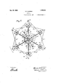
- Fig. 2 is a' plan view of my improved carrousel.
- FIG. 3 his a fragmental view partly in vertical section and partly broken away, show ing ⁇ one of the passenger carrying devices released and swung outwardly bv centrif* ugal force.
- F ig. l is a vertical sectional view of one of the sweeps, broken away, and some of the parts connected therewith, in positions occupied by them when at rest.
- Fig. 5 is a plan view of what is shown in 4;, the center pole being shown in cross section.
- Fig. 6 is an enlarged central vertical sectional view, partly broken away and parts omitted, of the center pole, support therefor, and parts connectedy therewith.
- Fig. is an enlarged vertical sectional view of a portion of one of the sweeps and some of the part mounted thereon.
- F ig. 8 is an elevation, partly broken away, of the mechanism for supporting the vertical driving shaft, a portion of which is shown.
- Fig. l1 is a plan view of the sectional sprocket wheel and portions of the sweeps which support it.
- Fig. l2 is an enlarged section on the line 12-12 of Fig. ii.
- Fig. 13 is an enlarged plan view of two adjacent end portions of two sprocket wheel sections.
- Fig. 14 is a sectional view on the line 9 is a section on the line 9-9 of l0 is a section on the line 10-10 of 'iiii of rig. e.
- l designates a center pole, preferably a steel tube, the lower end of which rests upon inner end portions of horizontal supporting H beams 2, having lips 3 which extend into the lowerend of the pole l, and having' respectively projections 4 which enter lateral holes 5 in the pole l, see Fig. 6 and Fig. 14.
- Upwardly and inwardly inclined brace bars 6 have peripheral flanges 7 at their lower ends respectively fitted in upwardly and outwardly facing arcuate grooves 8 with which the beams 2 adjacent to their outer ends are provided.
- the upper ends of the brace bars 6 have also peripheral flanges 7 which respectively lit in upwardly and outwardly facing arculll) ate grooves 9 in a sleeve 10 which is mounted on and fastened to the pole 1.
- the latter has upwardly facing arcuate grooves 11 in which are fitted the peripheral flanges 12 on the inner ends of transverse brace bars 13, the outer ends of which have similar flanges 14 fitted in upwardly facing' arcuate grooves 15 on the inner sides of the brace bars 6.
- the latter hold the pole 1 vertical, and the ars 13 hold the brace bars 6 in their posi tions.
- Rotatably mounted on the sleeve 10 is a hub 16 of a revoluble support, the hub havino; radial peripheral slots 17 in which are respectively removably fitted the inner ends of horizontal radial sweeps, cach of which comprises, preferably two angle bars 18 to the inner ends of which is fastened a plate 19, and a bracket 2O welded to and between the bars 18, the plates 19 being ⁇ respectively removably fitted in the hub holes or slots 17, Figs. 6 and 7.
- a plate 21 hav" ing a hook 22 at its upper end.
- Guy rods 23 having' hooks at their outer ends respectively engaging the hooks 22, and removabletherefrom, are provided at their upper ends with khooks 24 removably fitted respectively in holes 25 provided in a cap 26, Figs. 1 and t3, which is revoluble on a tubular central stem 27 of a circular plate 28 mounted in the upper end of the pole 1.
- Flach plate 21 has at its lower end a hook 30, Figs. 1 and 3.
- the hooks 30 have removably mounted in them eyes 31 respectively provided at the inner ends of radial rails 32, the outer ends of which curve outwardly and upwardly and have fastened to them respectively eyes 33 to which are connected links 34 which respectively are releasably engaged by hooks 35 at the outer ends of guy rods 86, the upper ends of which have hooks 37 removably fit-ted in holes provided therefor in the cap 26, Fig. 1 and Fig. 2.
- the rails 32 serve as tracks upon which are adapted to respectively rest and run wheeled carriages 3S, Figs. 1 and 3, one of which is provided with each passenger carrying device, each of which has four supporting rods fastened to its roof 40, the upper ends of the rods 39 beingfastened to a plate 41 which is pivoted to the car 1iage 38 by a transverse bolt 42, whereby the roof and parts supported by it may swing by centrifugal force outwardly.
- A. car 43 which may have suitable seats, is supported from the roof 40 by rods 44.
- crossed tie rods 44 may be detachably fastened to the outer ends of the rails 32 and to the outer ends of adjacent sweep bars 18.
- each sweep is mounted two bearings 45 in which is oscillatively mounted the upper end of a downwardly extending lever 4G, Figs. 4, 5 and 7 to the lower end of which is fastened a rod 47 the outer end of which has a hook 48 removably mounted in a hole provided therefore in the adjacent carriage 38, Figs. 1 and 3.
- Each lever 46 is provided with a concentric arcuate portion 49, Fig'. 7, on the periphery of which is mounted a cable 50, one end of which is fastened to the lever 4G and the other end of which is fastened to the outer end of a radial reciprocative member comprising a har 51 ⁇ which is mounted slidably in a slot provided therefor in an outer bearing, ⁇ 52 mounted on and welded to the sweep bars 18, Figs. i' and 9.
- the bar 51 also slidable in a slot provided therefor on an inner bearing ⁇ 53 also welded to the upper sides of the sweep bars 18.
- the cable will thus swing the lever 46 inwardly thus by means of the rod 47 pullinginwardly on the rail 32 the adjacent carriage 38 and with it the car 43 carried by said carriage.
- a lock nut 5 is on the bolt 58 and bears against the bearing ⁇ l
- a retracting coil spring- 60 has one end fastened to the inner end of the bar 51, the inner end of the spring being ⁇ attached to a radial bolt 61, Fig. 7, fitted in ay threaded Cil s of the teeth hole in the upper end of the adjacent bracket 20.
- a leck nut is mounted on the bolt 61 and is designated by 62.
- the springs 60 serve to retract the bars 51 inwardly when the sweeps are stationary andthe cars 48 assume the inner posit-ions shown in Fig. 1.
- the latter are provided each at its inner end with an upwardly extending arm 68.
- Respectively removably fitted on the arms 68 are eyes 64 at the outer ends of radial rods 65, two opposite ones of which are hinged on horizontal axes to opposite outer edges of two straps 66 which are respectively revoluble on two eccentrics 67, which are oppositely disposed and are mounted one above the other ou the hub of a gear wheel 68, Fig. 6, a vertical screw 69 being fitted in a vertical hole between the eccentric disks 67 and the hub of the gear wheel 68.
- One half of the number of the remainingl rods have at their inner ends hooks 70 litt-ed in holes provided in the upper strap 66, and the other half are similarly connected to the lower strap 66.
- oppositely disposed rods 65 are connected to opposite edges of different straps 66, so that the cars pulled in thereby will be simultaneously pulled in and simul taneously released, thereby equalizing. the strain on the structure.
- the gear wheel 68 meshes with a pinion 71, Fig. 6 fastened to a vertical shaft 72 rotatable in bearings 78 on the pole 1.
- vpinion 74 fastened to the shaft 72 meshes with teeth 75 provided on the periphery of the cap 26.
- this connecting gearing is such that relative movement in the same direction between the cap and the gear wheel 68 will occur.
- the pitch diameter 75 is 12 inches, that of the pinion 74 three inches, that of the pinion 71 rtwo andv one half inches, and that of the gear wheel 68 twelve and one half inches, the ⁇ cap 26 will make live revolutions to four of the gear wheel 68, and the carriages 88 and cars 48 will each be. once drawn inwardly and suddenly released during live revolutions of the cap 26 and sweeps 18.
- a horizontal drivingl wheel which is preferably a sprocket wheel and which is constructed as follows.
- the sprocket wheel is made, preferably, in sections 76, Figs. 1, 2, 1l, 12 and 18, each ef which at one end has two arms 77 each having on opposite sides respectively .notches 78 adapted to receive two pins 79 with which each end of each section 76, excepting one, is provided.
- the arms 77 of one section are inserted between the. pins 79 of the next adjoining section, after which the next section is similarly engaged with the last one, and so on until the last section which is the one having the hole 80.
- This section has its arms 77 fitted in the last section between the pins thereof, and is then swung to the circular position, Fig. 11, in which position the hole 80 will aline with one of the notches in each arm 77 of the adjacent section.
- the pin 81 is then inserted in the hole 80 and in the adjoining notches 78, whereby the sections of the wheel will all be locked firmly together.
- each section 76 is provided with notches 82 adapted to respectively receive bracket pins 88, Fig. 7, one of which is vertically slidable in a vertical hole 84: ofA each bracket 20.
- the latter is provided with a lateral notch 85 in its outer side adapted to receive'the adjacent wheel section 76, and the pin 88 may have a laterally extending pin 86 slidable in a slot 87 which communicates with the hole 84.
- the pin 88 may be lifted clear of the section 76.
- Fig. 18 is shown the manner of insertion of the arms 77 between the pins 79.
- the sprocket wheel is engaged by a sprocket chain 87I which engages a sprocket wheel 88 fastened to a vertical driving shaft 89, Figs. 8 and 10, the lower end of which is rotatable in a bracket 90, Fig. 1, which mounted on one of the beams 2.
- the upper end of the shaft 89 is rotatable in a bearing comprising an elbow 92 having a semicircular recess 91, Fig. 10, which co-operates with a similar recess 98 in a cap 94 hinged on a vertical pin 95 to the elbow 92.
- the cap has two lugs 96 between which is adapted to be swung a bolt 97 hinged to the elbow 92, and having a nut 98 bearing against the lugs 96.
- Guy braces 108 have at their upper ends hooks 104 respectively removably fitted in eyes 105 on opposite sides of the elbow 92, Figs. l, 2, 8 and 10. The lower ends of the braces 108 have hooks 106 respectively removably attached to eyes 107 on two opposite disposed beams 2.
- Each brace '103 may be provided with a turubuclile 108, for adjusting,V and tigghteningT said braces.
- Two tie rods 103 are attached to the outer ends of the beains 2, having attached to tliein the braces 103, said rods 10i being' Jinsterred to the outer end ot the beam 2, which opposite to the one to which is attached the bar G provided with the projection 100.
- a clutch 113 l may be driven by a suiton and rotatable with the shaft 110 is adapted to e rage and to be di er pulley 112.
- a bell crankv lever 1 to a bearing; on the pole 1, engaging; the clutch 113, the othe arin being; ⁇ pivoted to the lower end ot a link 11G, pivoted at its upper end to a. horizontal operating; bar 11T slidable in bearinc 118 and 119 respectively mounted on one ot the bars 6 and the pole 1, 1.
- Pivoted on the bearing 115 on the pole 1. is another' bell crank lever 120, one arrn of which is pivoted to the operating ⁇ bar 117, and the other arin ot which is pivoted to a rod 121 connected to a brake strap 122 which is adapted to einbrace a brake wheel 123 fastened to .the shaft 110.
- the clutch 113 will be inade to operatively engage the cone pulley 112 so as to be rotated thereby, thereby rotating ⁇ the shaft 110, and through the interncdiacy ot the ⁇ nears 109, 109, shaft 8f), )roel-:et wheel S8, chain 87 and sectional si revolvingthe sweeps 18, and thereby revolvini; the cars 13 around the pole 1.
- the cap 2G and the plate 28 may then be n Y.ed michn the pole 1. rlhe rods 65 are then detached from the arlns 63 ot' the bars 54 and :trein the eccentric straps 6G.
- the tie rods eel are detached troni the beams 18, and the sections 76 ot the sectional sprocket 1 wheel are the beams 2, and the brace bars 103 are detached form the beams 2 and elbow 92.
- the operating bar 117 is Withdrawn from its bearings 118 and 119 after having been detached from the link 116 and the bell crank lever 120.
- the gear 109 is loosened on the shaft 110 and the latter is detached therefrom and from the bracket 90 and bearing 111.
- the bell crank lever 114 is detached from the clutch 113, and the rod 121 detached from the bell crank lever 120.
- the nut 98 is loosened and the bolt 97 swung to release the cap bearing 94, upon which the shaft 89 may be detached from the bearing elbow 92 and lifted outof the bracket 90.
- brace bars 13 are then lifted from the grooves 11 and 15 of the pole 1 and bars G. The latter may now be withdrawn outwardly from the grooves 8 and 9 in the beams 2 and sleeve 10.
- the beams 2 may now be unhooked and detached from the pole 1 and the latter lowered by reversing the operation describedv with reference to the assembling of these parts.
- a revolving support supporting means therefor, a passenger cai'- rying device movable outwardly by natural force on said support, and means connecting said device with said supporting means by which said device, during the revolutions of said support, is periodically forced inwardly and is then released and permitted to move freely outwardly.
- a revolving support support-ing means therefor, apassenger caru rying device movable outwardly by centrifugal force on said support, and means connecting said device with said supporting' means by which said device, during the revolutions of said support, is periodically forced inwardly and is then released and permitted to move freely outwardly.
- a revolving support supporting means therefor, a passenger cai'- rying device movable outwardly on said support by natural force, and means connecting said device with said supporting means by which said device, during the revolutions of said support, is periodically forced inwardly and is then suddenly released and permitted to move freely outwardly.
- a revolving support supporting means therefor, a passenger carrying device movable outwardly by centrifugal force on said support, and means connecting said device with said supporting .means by which said device, during the revolutions of said support, is periodically forced inwardly and is then suddenly released and permitted to move freely out ⁇ wardly.
- a revolving support having a radial track, supporting means for said support, a passenger carrying device movable outwardly by natural force on said track, and means connecting said device with said supporting means by which said device, during the revolutions of said support, is periodically moved inwardly on said track and is then permitted to be released and to move freely outwardly on said track.
- a revolving support having a radial track which yextends outwardly and upwardly, supporting means for said support, a passenger carrying device movable outwardly and upwardly by centrifugal force on said track, and means connecting said device with said supporting means by wliiclisaid device, during the revolutions of said support, is periodically forced inwardly on said track against said centrifugal force and is then permitted to move freely outwardly on said track.
- a revolving support a passenger carrying device movable outwardly by natural force on said supporting means for said revolving support, an eccentric mounted on said supporting means, and means actuated by said eccentric, by which said device, during the revolutions of said support, is periodically forced inwardly against the action of said force and is then released and permitted to move outwardly.
- a revolving support a stationary support therefor, a passenger carrying device movable outwardly by natural force on said revolving support, an eccentric disk, means on said stationary support for supporting said disk, said revolving support being revoluble relatively to said disk, and means actuated by said disk by which said device, during the revolutions of said revolving support, is periodically forced inwardly and is then released and permitted to move outwardly.
- a revolving support a stationary support therefor, a passenger carrying device movable outwardly by natural force on said revolving support when the latter revolves, an eccentric disk revoluble relatively to said revolving support on said stationary support, means for so revolving said disk and said revolving support, and means actuated by said disk by which said device, during the revolutions of said revolving support, is periodically forced inwardly and is then released and permitted to move outwardly.
- said device is periodically forced inwardly and then released and permitted to move outwardly.
- a carrousel1 a center pole, a support revoluble thereon, a passenger carrying device movable outwardly by natural force onsaid support lwhen the latter is revolved, an eccentric disk revoluble on said pole relatively to said support, and means actuated by said disk by which, when said support is revolved,said device is periodically forced inwardly and is then released and permitted to move outwardly.
- a carrousel a center pole, a support revoluble thereon, two passenger carrying devices mounted on said support at opposite sides respectively of said pole and movable outwardly on said support by natural force when said support is revolved, and means connecting said device with said supporting means by which said devices, during the revolutions of said support, are periodically forced inwardly simultaneously and are then simultaneously released and permitted to move freely outwardly.
- a carrousel a revoluble support, supporting means therefor, two passenger carrying devices mountedron said support at opposite sides respectively of. the axis of said support and movable outwardly thereon by natural force when said support is revolved, and means connecting said device with said supporting means by which said devices, during ⁇ the revolutions of said sup port are periodically forced inwardly simultaneously and are then simultaneously released and permitted to move freely outwardly.
- 1G. ln a carrousel, a stationary support, a
- a revoluble support a passenger carrying device movable outwardly thereon by natural force when said support is revolved, member reciprocative on said support, means for reciprocating said meinber when the support is revolved, and means actuated by said reciprocative member by which said device is periodically forced inwardly and is then released and permitted to move outwardly.
- a carrousel a revoluble support, a passenger carrying device ⁇ movable outwardly thereon by natural force when support is revolved, two members reciprocative on said support, a latch carried by one of said members and adapted to operatively engage the other member, whereby said niembers may move conjointly inwardly,r means in the path of said latch for engaging and reeesoo moving it to the release position, means by which when support is revolved one of said members will be reciproca-ted thereby, and means actuated by the other member when it is inwardly moved for forcing said device inwardly.
- a carrousel a stationary support, a support revoluble thereon, a passenger carrying device suspended from and adapted to travel and to swing outwardly on said revoluble support by natural torce, and means connecting said device with said supporting means by which said device, during the revolutions of said revoluble support, is forced inwardly against said force and is then released and permitted to move freely outwardly.
- a carrousel a stationary support, a support revoluble thereon, a passenger carrying device suspended from and adapted to travel and to swing outwardly by natural force on said revoluble support when the latter is revolved, an eccentric disk mounted on said stationary support and relatively to which said revoluble support is revoluble, and means actuated by said disk by which said device, during the revolutions of said revoluble support, is i''orlced inwardly and is then periodically released and permitted to move outwardly.
- a revoluble support In a carrousel, a revoluble support, a stationary support therefor, a passenger carrying ⁇ device movable outwardly on said revoluble support by natural force when said revoluble support is revolved, an eccentric disk mounted on said stationary support, means by which said disk is revolved relatively to said revoluble support, a. strap revo-lubly engaging said disk, av member reciprocative on said revoluble support, a rod connecting said member and said strap, a second member reciprocative on said revoluble support, a.
- latch connecting said members by which said second member is moved in one direction simultaneously with the other member, means in the path ot travel of said latch .tor engaging and releasing the latch, and means actuated by said second member for forcing said device inwardly when said latch is operatively engaging both of said members.
Landscapes
- Seats For Vehicles (AREA)
Description
C. E. MORRIS Dec. 2s, 192s.
CARCUSEL Filed ,July 26, 1926 mix eh. h. Nn.
NQS m n 2v, w
h RQ o3 ow mx.
m. ew um mm\m INVENTOR /a A Troie/v5 Y 2s, 1928. C. E. MORRIS CAROUSEL Filed July 26, 1925 5 Sheets-Sheet 2 #a A TTG/@NE Y WTNESSES:
C. E. MORRIS CAROUS EL e sheets-smet 3 Filed July 26, 1926 L /NVEN TOR.
` #fb A TTU/NE Y WITNESS:v
Dec. 25, 1928. 1,696,500
c. E. MORRIS CAROUSEL Filed July 2s, 192e e sheaves-sheet*t 4 7% f l f 2J 23 2# 526 l l u i 4f I/IJTNESSES 6 Q MW A TTORNE Y NVENTOR.
Dec. 25, 192s.
C. E. MORRIS CA'ROUS EL Filed July 26, 1926 6 Sheets-Sheet 5 r4 ff Vlflllllillllilllllnl.
i '414 l J n .wz/5N TOR. 771mm/ 1,696,500 c.' E. MORRIS cAnoUsEL Filed Jul 26. 19 6 6 Sheets-Sheet Maa/ww @71911417 WJTNESSES-- 9 v INVENTR.
/f-d ATTORNEY Patented Dec. 25, 1928.
CHARLES E. MORRIS, 0F LEAVENWORTH, KANSAS.
CARROUSEL.
Application filed July 26,
My invention relates to improvements in carrousels.
It is particularly well adapted for use in connection with carrousels of a type having a center pole on which are revoluble radial sweeps from which passengercarrying devices, such as swings, are suspended and are adapted for inward and outward movement thereon.
One of the objects of my invention is to provide a carrousel of the kind described with novel means by which the passenger' carrying devices move outwardly by a natural force, which may be centrifugal force effected by the revolution of the support for the passenger carrying devices, and by which the devices are periodically mechanically forced inwardly against said force, and are then suddenly released and permitted to move quickly outwardly, whereby the passengers obtain pleasing and thrilling sensations.
A further object of my invention is to provide a novel arrangement by which oppositely disposed passenger carrying` devices are simultaneously forced inwardly and released, so as to equalize the strain upon the structure.
My invention provides further novel means for supporting the passenger carrying devices, whereby the latter in their outwai'd movement also move upwardly.
My invention provides still further a sti'ucture which is relatively simple and cheap, which is durable, safe, strong, not liable to get out of order` which can be easily and quickly assembled in operative condition, and as readily disassembled, which has interlocking parts so arranged as to dispense with accessory fastening devices, such as bolts and nuts, that are liable to loosen in use, and which has novel driving means for the moving parts.
The novel features of my invention are hereinafter fully described and claimed.
In the accompanying drawings, which illustrate the preferred embodiment of my invention.
Fig. l is a view partly in side elevation and partly in vertical section, and partly broken away, of my improved carrousel shown in the position occupied by the parts when the movable parts are at i'est.
Fig. 2 is a' plan view of my improved carrousel.
1926'. Serial vNo. 124,935.
Fig. 3 his a fragmental view partly in vertical section and partly broken away, show ing` one of the passenger carrying devices released and swung outwardly bv centrif* ugal force. Y
F ig. l is a vertical sectional view of one of the sweeps, broken away, and some of the parts connected therewith, in positions occupied by them when at rest.
Fig. 5 is a plan view of what is shown in 4;, the center pole being shown in cross section.
Fig. 6 is an enlarged central vertical sectional view, partly broken away and parts omitted, of the center pole, support therefor, and parts connectedy therewith.
Fig. is an enlarged vertical sectional view of a portion of one of the sweeps and some of the part mounted thereon.
F ig. 8 is an elevation, partly broken away, of the mechanism for supporting the vertical driving shaft, a portion of which is shown.
Fig. Fig. 7.
Fig. F ig. 8.
Fig. l1 is a plan view of the sectional sprocket wheel and portions of the sweeps which support it.
Fig. l2 is an enlarged section on the line 12-12 of Fig. ii.
Fig. 13 is an enlarged plan view of two adjacent end portions of two sprocket wheel sections.
Fig. 14 is a sectional view on the line 9 is a section on the line 9-9 of l0 is a section on the line 10-10 of 'iiii of rig. e.
Similar reference characters designate similar parts in the different viewi. Y
l designates a center pole, preferably a steel tube, the lower end of which rests upon inner end portions of horizontal supporting H beams 2, having lips 3 which extend into the lowerend of the pole l, and having' respectively projections 4 which enter lateral holes 5 in the pole l, see Fig. 6 and Fig. 14.
Upwardly and inwardly inclined brace bars 6 have peripheral flanges 7 at their lower ends respectively fitted in upwardly and outwardly facing arcuate grooves 8 with which the beams 2 adjacent to their outer ends are provided.
The upper ends of the brace bars 6 have also peripheral flanges 7 which respectively lit in upwardly and outwardly facing arculll) ate grooves 9 in a sleeve 10 which is mounted on and fastened to the pole 1. The latter has upwardly facing arcuate grooves 11 in which are fitted the peripheral flanges 12 on the inner ends of transverse brace bars 13, the outer ends of which have similar flanges 14 fitted in upwardly facing' arcuate grooves 15 on the inner sides of the brace bars 6. The latter hold the pole 1 vertical, and the ars 13 hold the brace bars 6 in their posi tions.
Rotatably mounted on the sleeve 10 is a hub 16 of a revoluble support, the hub havino; radial peripheral slots 17 in which are respectively removably fitted the inner ends of horizontal radial sweeps, cach of which comprises, preferably two angle bars 18 to the inner ends of which is fastened a plate 19, and a bracket 2O welded to and between the bars 18, the plates 19 being` respectively removably fitted in the hub holes or slots 17, Figs. 6 and 7.
Between each pair of sweep bars 18 at the outer ends thereof is welded a plate 21 hav" ing a hook 22 at its upper end. Guy rods 23 having' hooks at their outer ends respectively engaging the hooks 22, and removabletherefrom, are provided at their upper ends with khooks 24 removably fitted respectively in holes 25 provided in a cap 26, Figs. 1 and t3, which is revoluble on a tubular central stem 27 of a circular plate 28 mounted in the upper end of the pole 1.
rlhe plate 2S supports rollers 29 upon weich rests the cap 26, Fig. 6.
The rails 32 serve as tracks upon which are adapted to respectively rest and run wheeled carriages 3S, Figs. 1 and 3, one of which is provided with each passenger carrying device, each of which has four supporting rods fastened to its roof 40, the upper ends of the rods 39 beingfastened to a plate 41 which is pivoted to the car 1iage 38 by a transverse bolt 42, whereby the roof and parts supported by it may swing by centrifugal force outwardly. A. car 43, which may have suitable seats, is supported from the roof 40 by rods 44.
A shown in Fig. 2, crossed tie rods 44 may be detachably fastened to the outer ends of the rails 32 and to the outer ends of adjacent sweep bars 18.
lV hen the sweeps are revolved with the hub 16 on the sleeve 10, the centrifugal force will cause the cars 43 to swing outwardly and the carriages 38 to travel outwardly and then upwardly on the rails 32, Fig'. 3. In order that the passenger carrying cars 43 and the carriages which support them, maybe forced inwardly against the centrifugal force which forces them outwardly, the following described. mechanism may be provided.
Upon each sweep is mounted two bearings 45 in which is oscillatively mounted the upper end of a downwardly extending lever 4G, Figs. 4, 5 and 7 to the lower end of which is fastened a rod 47 the outer end of which has a hook 48 removably mounted in a hole provided therefore in the adjacent carriage 38, Figs. 1 and 3.
Each lever 46 is provided with a concentric arcuate portion 49, Fig'. 7, on the periphery of which is mounted a cable 50, one end of which is fastened to the lever 4G and the other end of which is fastened to the outer end of a radial reciprocative member comprising a har 51` which is mounted slidably in a slot provided therefor in an outer bearing,` 52 mounted on and welded to the sweep bars 18, Figs. i' and 9. The bar 51 also slidable in a slot provided therefor on an inner bearing` 53 also welded to the upper sides of the sweep bars 18.
Similarly reciprocative in the bearings 52 and is a radial bar 54, above the bar 51, and which has pivoted to it on a horizontal axis by a bolt 55, a latch 56, which is adapted to drop by gravity into a, notch 57 in the upper edge of the bar 51, Fig. 7.
When the bar 54 is forced inwardly, as will be described, due to the revolution of the sweep, the latch 56 will enter the notch 5T, and the bar 51 will be forced longitudinally inwardly therewith.
The cable will thus swing the lever 46 inwardly thus by means of the rod 47 pullinginwardly on the rail 32 the adjacent carriage 38 and with it the car 43 carried by said carriage.
To release the latch 56 from the bar 51 at a predetermined point, there is provided an abutment comipnising` a radial bolt 58, Fig. 7, which is fitted in threaded holel in the inner bearing; 5B. and which is in the )ath of the upper end of the latch 56. A lock nut 5) is on the bolt 58 and bears against the bearing` lWhen the latch 56 strikes the bolt 5S, the latch will be swung out of the notch 57, and the centrifugal force will force the car 43 and the carriage 38 suddenly outwardly, `thus imparting a pleasing and thrilling sen-- sation to the passengers in the car.
A retracting coil spring- 60 has one end fastened to the inner end of the bar 51, the inner end of the spring being` attached to a radial bolt 61, Fig. 7, fitted in ay threaded Cil s of the teeth hole in the upper end of the adjacent bracket 20. A leck nut is mounted on the bolt 61 and is designated by 62.
The springs 60 serve to retract the bars 51 inwardly when the sweeps are stationary andthe cars 48 assume the inner posit-ions shown in Fig. 1.
For forcing the bars 5a inwardly, the latter are provided each at its inner end with an upwardly extending arm 68. Respectively removably fitted on the arms 68 are eyes 64 at the outer ends of radial rods 65, two opposite ones of which are hinged on horizontal axes to opposite outer edges of two straps 66 which are respectively revoluble on two eccentrics 67, which are oppositely disposed and are mounted one above the other ou the hub of a gear wheel 68, Fig. 6, a vertical screw 69 being fitted in a vertical hole between the eccentric disks 67 and the hub of the gear wheel 68.
One half of the number of the remainingl rods have at their inner ends hooks 70 litt-ed in holes provided in the upper strap 66, and the other half are similarly connected to the lower strap 66. By this arrangement oppositely disposed rods 65 are connected to opposite edges of different straps 66, so that the cars pulled in thereby will be simultaneously pulled in and simul taneously released, thereby equalizing. the strain on the structure.
The gear wheel 68 meshes with a pinion 71, Fig. 6 fastened to a vertical shaft 72 rotatable in bearings 78 on the pole 1. A
The ratio of" this connecting gearing is such that relative movement in the same direction between the cap and the gear wheel 68 will occur. Thus if the pitch diameter 75 is 12 inches, that of the pinion 74 three inches, that of the pinion 71 rtwo andv one half inches, and that of the gear wheel 68 twelve and one half inches, the` cap 26 will make live revolutions to four of the gear wheel 68, and the carriages 88 and cars 48 will each be. once drawn inwardly and suddenly released during live revolutions of the cap 26 and sweeps 18.
For driving the sweeps, there secured to the brackets 20 under the sweep members 18 a horizontal drivingl wheel, which is preferably a sprocket wheel and which is constructed as follows.
The sprocket wheel is made, preferably, in sections 76, Figs. 1, 2, 1l, 12 and 18, each ef which at one end has two arms 77 each having on opposite sides respectively .notches 78 adapted to receive two pins 79 with which each end of each section 76, excepting one, is provided.
One of the sections 76, Fig, 11 and Fig.
12 has a hole 80 in which is removably fitted a pin 8l.
In assembling the sections 76, the arms 77 of one section are inserted between the. pins 79 of the next adjoining section, after which the next section is similarly engaged with the last one, and so on until the last section which is the one having the hole 80. This section has its arms 77 fitted in the last section between the pins thereof, and is then swung to the circular position, Fig. 11, in which position the hole 80 will aline with one of the notches in each arm 77 of the adjacent section. The pin 81 is then inserted in the hole 80 and in the adjoining notches 78, whereby the sections of the wheel will all be locked firmly together.
The inner side of each section 76 is provided with notches 82 adapted to respectively receive bracket pins 88, Fig. 7, one of which is vertically slidable in a vertical hole 84: ofA each bracket 20. The latter is provided with a lateral notch 85 in its outer side adapted to receive'the adjacent wheel section 76, and the pin 88 may have a laterally extending pin 86 slidable in a slot 87 which communicates with the hole 84. By means ofthe pin 86 the pin 88 may be lifted clear of the section 76. In Fig. 18 is shown the manner of insertion of the arms 77 between the pins 79.
The sprocket wheel is engaged by a sprocket chain 87I which engages a sprocket wheel 88 fastened to a vertical driving shaft 89, Figs. 8 and 10, the lower end of which is rotatable in a bracket 90, Fig. 1, which mounted on one of the beams 2. The upper end of the shaft 89 is rotatable in a bearing comprising an elbow 92 having a semicircular recess 91, Fig. 10, which co-operates with a similar recess 98 in a cap 94 hinged on a vertical pin 95 to the elbow 92. For holding the cap in operative position, it has two lugs 96 between which is adapted to be swung a bolt 97 hinged to the elbow 92, and having a nut 98 bearing against the lugs 96.
In the horizontal arm of the elbow 92 is fitted removably a pipe 99, Figs. l and 8, in the inner end of which is removably fitted a projection 100 on the outer side of an adjacent bar 6. In the vertical arm of the elbow 92 is fitted the upper end of a vertical pipe 101, in the lower end of which is re movably fitted a projection 102, which is on the outer side of the bar 6 having the projection 100.
Guy braces 108 have at their upper ends hooks 104 respectively removably fitted in eyes 105 on opposite sides of the elbow 92, Figs. l, 2, 8 and 10. The lower ends of the braces 108 have hooks 106 respectively removably attached to eyes 107 on two opposite disposed beams 2. Each brace '103 may be provided with a turubuclile 108, for adjusting,V and tigghteningT said braces.
Two tie rods 103, Figs. 1 and 2, are attached to the outer ends of the beains 2, having attached to tliein the braces 103, said rods 10i being' Jinsterred to the outer end ot the beam 2, which opposite to the one to which is attached the bar G provided with the projection 100.
For rotating` the shatt Si) it has 'fastener-L to it a bevel gear wheel llll, which meshes with a bevel ,(ear wheel 109 secured to a horizontal shattrotatable at one end iii the braclretl 90, and. rotatable its other end in a bearing` 111, secured to the pole 1. Fig. 1. A cone pulley is rotatable en the shaft 110, ant
ably driven belt, not shown. A clutch 113 l may be driven by a suiton and rotatable with the shaft 110 is adapted to e rage and to be di er pulley 112. A bell crankv lever 1 to a bearing; on the pole 1, engaging; the clutch 113, the othe arin being;` pivoted to the lower end ot a link 11G, pivoted at its upper end to a. horizontal operating; bar 11T slidable in bearinc 118 and 119 respectively mounted on one ot the bars 6 and the pole 1, 1. l
Pivoted on the bearing 115 on the pole 1. is another' bell crank lever 120, one arrn of which is pivoted to the operating` bar 117, and the other arin ot which is pivoted to a rod 121 connected to a brake strap 122 which is adapted to einbrace a brake wheel 123 fastened to .the shaft 110.
lVhen the operatingbar 11(i is pulled out wardly, the clutch 113 will be inade to operatively engage the cone pulley 112 so as to be rotated thereby, thereby rotating` the shaft 110, and through the interncdiacy ot the `nears 109, 109, shaft 8f), )roel-:et wheel S8, chain 87 and sectional si revolvingthe sweeps 18, and thereby revolvini; the cars 13 around the pole 1.
Then the bar 11"( is forced inwardly to the position shown in Fig. 1, the bell crank lever is swung to tighten the brake strap 122 on the brake wheel 123, thus stopping revolution ot the shaft 110 and the passen 3315er carrying' devices.
TWhen the bar 1T is pulled outwardly to start the revolving' ot the sweeps, the bell crank lever 121.) is swung' so to release the brake. wheel 123 fro-rn the stre is the sweeps are revolve 16. the straps 66 will be revolved on the eccentric disks GT. and tl e guy rods 23 and Zl' will revolve the eap 2G, which in turn, by ineans ot the pinion 74, shaft 72, pinion 71. will remlve the gear wheel with it the eccentric disks 6?, in the saine direction as the cap 26 tour revolutions to live revolutions of the cap, the ratio of the gearing being,` so proportioned, as before described.
)rocket wheel 76,
rlhus each pair ot oppositely disposed bars will be simultaneously drawn inwardly troni the position shown in Fig. 7 once during every live revolutions of the sweep bars 18, and in being` so drawn the latches 56 can ried by said bars 54: will enter the notches ot the adjacent bars 51, thereby drawing inwardly the latter and with thein the adj acent levers 16, by ineans ot the cables 50, thus drawing` inwardly1 by means of the rods 47, the. adjacent carriages 38 and the cars 413 supported thereby.
lhen the latches engage the adjacent bolts 58, the latter w'll swing the latches 56 out ot the notches 5?, and the bars 51, which have been drawn inwardly by the latches will. be suddenly released, and the carriao'es 3S, being; released, will, with the cars 3, be Jorced rapidly outwardly by centrifu'ral torce, the sweeps being; revolved at the time. The carriages 38 will travel outwardly and then upwardly on the rails 32 which support thein, and the carriages 38 and cars L13 will assuine the position shown in 3, and will so remain until the cars have completed live more. revolutions and the bars 51 are again inwardly drawn, or until the sweeps stop revolving.
@ppositely disposed pairs of carriages and cars will 'thus be simultaneously drawn and released consecutively.
Willen the operating' bar 117 is forced inwardly to the position shown in Fig. 1, the sweep bars 18 will stop revolving and the carriages 38 will run inwardly on the rails 32 to the position shown in Fig'. 1. The springs GO will retract inwardly the bars 51 to the positions shown in Figs. '1, l and 5, where they will remain until the carriages and cars are again 'forced outwardly by entritugal torce to the position shown in ln disasseinbling. the rods l? are detached from the carriages 38, and the rods 5l and 36 are detached .troni the cap 26 and from the hooks 22 and links 34: respectively. T he rails inay then be detached 'frein the hoolrs i); and talren down with the carriages 38, the rodn el having' been detached :troni the rails.
The cap 2G and the plate 28 may then be n Y.ed frein the pole 1. rlhe rods 65 are then detached from the arlns 63 ot' the bars 54 and :trein the eccentric straps 6G.
The tie rods eel are detached troni the beams 18, and the sections 76 ot the sectional sprocket 1 wheel are the beams 2, and the brace bars 103 are detached form the beams 2 and elbow 92. The operating bar 117 is Withdrawn from its bearings 118 and 119 after having been detached from the link 116 and the bell crank lever 120.
The gear 109 is loosened on the shaft 110 and the latter is detached therefrom and from the bracket 90 and bearing 111. The bell crank lever 114 is detached from the clutch 113, and the rod 121 detached from the bell crank lever 120.
The nut 98 is loosened and the bolt 97 swung to release the cap bearing 94, upon which the shaft 89 may be detached from the bearing elbow 92 and lifted outof the bracket 90.
The brace bars 13 are then lifted from the grooves 11 and 15 of the pole 1 and bars G. The latter may now be withdrawn outwardly from the grooves 8 and 9 in the beams 2 and sleeve 10.
The beams 2 may now be unhooked and detached from the pole 1 and the latter lowered by reversing the operation describedv with reference to the assembling of these parts.
What I rclaim:---
1. In a cariousel, a revolving support, supporting means therefor, a passenger cai'- rying device movable outwardly by natural force on said support, and means connecting said device with said supporting means by which said device, during the revolutions of said support, is periodically forced inwardly and is then released and permitted to move freely outwardly. y
2. In a carrousel, a revolving support, support-ing means therefor, apassenger caru rying device movable outwardly by centrifugal force on said support, and means connecting said device with said supporting' means by which said device, during the revolutions of said support, is periodically forced inwardly and is then released and permitted to move freely outwardly.
3. In a carrousel, a revolving support, supporting means therefor, a passenger cai'- rying device movable outwardly on said support by natural force, and means connecting said device with said supporting means by which said device, during the revolutions of said support, is periodically forced inwardly and is then suddenly released and permitted to move freely outwardly.
4.-. In a carrousel, a revolving support, supporting means therefor, a passenger carrying device movable outwardly by centrifugal force on said support, and means connecting said device with said supporting .means by which said device, during the revolutions of said support, is periodically forced inwardly and is then suddenly released and permitted to move freely out` wardly.
5. In a carrousel, a revolving support having a radial track, supporting means for said support, a passenger carrying device movable outwardly by natural force on said track, and means connecting said device with said supporting means by which said device, during the revolutions of said support, is periodically moved inwardly on said track and is then permitted to be released and to move freely outwardly on said track.
6. In a carrousel, a revolving support having a radial track which yextends outwardly and upwardly, supporting means for said support, a passenger carrying device movable outwardly and upwardly by centrifugal force on said track, and means connecting said device with said supporting means by wliiclisaid device, during the revolutions of said support, is periodically forced inwardly on said track against said centrifugal force and is then permitted to move freely outwardly on said track.
7. In a carrousel, a revolving support, a passenger carrying device movable outwardly by natural force on said supporting means for said revolving support, an eccentric mounted on said supporting means, and means actuated by said eccentric, by which said device, during the revolutions of said support, is periodically forced inwardly against the action of said force and is then released and permitted to move outwardly.
8. In a carrousel, a revolving support, a stationary support therefor, a passenger carrying device movable outwardly by natural force on said revolving support, an eccentric disk, means on said stationary support for supporting said disk, said revolving support being revoluble relatively to said disk, and means actuated by said disk by which said device, during the revolutions of said revolving support, is periodically forced inwardly and is then released and permitted to move outwardly.
9. In a carrousel, a revolving support, a stationary support therefor, a passenger carrying device movable outwardly by natural force on said revolving support when the latter revolves, an eccentric disk revoluble relatively to said revolving support on said stationary support, means for so revolving said disk and said revolving support, and means actuated by said disk by which said device, during the revolutions of said revolving support, is periodically forced inwardly and is then released and permitted to move outwardly.
10. In a carrousel, a center pole, a` support i'evoluble thereon, a passenger carry- Ving device movable outwardly by natural force on said support when the latter revolves, an eccentric disk mounted on said pole and relative to which said support is revoluble, and means actuated by said disk by which, when said support is revolved,
Cil
said device is periodically forced inwardly and then released and permitted to move outwardly.
11. In a carrousel1 a center pole, a support revoluble thereon, a passenger carrying device movable outwardly by natural force onsaid support lwhen the latter is revolved, an eccentric disk revoluble on said pole relatively to said support, and means actuated by said disk by which, when said support is revolved,said device is periodically forced inwardly and is then released and permitted to move outwardly.
12. ln a carrousel, a center pole, a support revoluble thereon, a passenger carrying device movable outwardly by natural force on said support when the latter revolved, an eccentric disk revoluble on said pole, driving means by which said support and said` disk are revolved at different rates of revolutions, and means actuated by said disk by which said device, during the revolutions of said support, is periodically forced inwardly and is then released and permitted to move outwardly.
13. In a carrousel, acenter pole, a support revoluble thereon and having a gear wheel revoluble on said pole concentrically therewith, al passenger carrying device movable outwardly on said support by natural force when the support is revolved, a second gear wheel revoluble on said pole, an eccentric disk mounted on and revoluble with said second gear wheel, gearing connecting said two gears by which the latter will revolve relatively to each other, and means actuated by said disk for periodically forcing inwardly said device and then releasing it to permit it to move outwardly.
141-. In a carrousel, a center pole, a support revoluble thereon, two passenger carrying devices mounted on said support at opposite sides respectively of said pole and movable outwardly on said support by natural force when said support is revolved, and means connecting said device with said supporting means by which said devices, during the revolutions of said support, are periodically forced inwardly simultaneously and are then simultaneously released and permitted to move freely outwardly.
15. ln a carrousel, a revoluble support, supporting means therefor, two passenger carrying devices mountedron said support at opposite sides respectively of. the axis of said support and movable outwardly thereon by natural force when said support is revolved, and means connecting said device with said supporting means by which said devices, during` the revolutions of said sup port are periodically forced inwardly simultaneously and are then simultaneously released and permitted to move freely outwardly.
1G. ln a carrousel, a stationary support, a
revoluble support thereon, two passenger carrying devices mounted on said revoluble support at opposite sides respectively of` the axis of said revoluble support and movable outwardly on said revoluble support by natural force when the revoluble support is revolved, two oppositely disposed eccentric disks mounted on said statinary support and relatively to which said, revoluble support is revoluble, and means actuated by said disks by which said devices, during the revolutions of said revoluble support, are periodically rforced inwardly simultaneously and are then simultaneously released and permitted to more outwardly.
l?. ln a carrousel, a revoluble support, a stationary support there'i'for, two passenger carrying devices mounted on said revoluble support at `opposite sides respectively of the axis ofthe latter and movable outwardly by natural force when said revoluble support is revolved, two oppositely disposed eccentric disksrevoluble together on said stationary support, means actuated by said disks by wnich said de fices, during tlie revolutions of said revoluble support, are simultaneously forced inwardly and are then simultaneously released and permitted to move outwardly, and drivingmeans connecting said disks and said revoluble support by which the latter and said disks are revolved relatively to each other.
18. In a carrousel, a revoluble support, a passenger carrying device movable outwardly thereon by natural force when said support is revolved, member reciprocative on said support, means for reciprocating said meinber when the support is revolved, and means actuated by said reciprocative member by which said device is periodically forced inwardly and is then released and permitted to move outwardly.
19, ln a carrousel, a revoluble support, a stationary support therefor, a passenger carrying device movable outwardly by natural force on said revoluble support when the latter' is revolved, a member ren ciprocative on said revoluble support, an eccentric disk mounted on said stationary support and relatively to which said revo luble support is revoluble, means actuated by said disk for reciprocating said member, and means by which when said member is reciprocated, said device will be forced inwardly and then released and permitted to move outwardly.
20. In a carrousel, a revoluble support, a passenger carrying device` movable outwardly thereon by natural force when support is revolved, two members reciprocative on said support, a latch carried by one of said members and adapted to operatively engage the other member, whereby said niembers may move conjointly inwardly,r means in the path of said latch for engaging and reeesoo moving it to the release position, means by which when support is revolved one of said members will be reciproca-ted thereby, and means actuated by the other member when it is inwardly moved for forcing said device inwardly.
2l. ln a carrousel, a revoluble support Icarrying an abutment, a. passenger carrying device movable outwardly by atural torce on said support when the latter revolves, a. stationary support on which said revoluble support is revoluble, an eccentric dislr mounted on said stationary support, a member reciprocative on said revoluble support, means actuated by said disk for reciprocating said member, a second member reciprocative on said revoluble support, a latch mounted on one of said reciprocative members and engaging` the other reciprocative member whereby said members will m ve inwardly conjointly, said abutment being in the path otI and arranged to engage and move said latch to the release position, and means by which said second member on its inward movement will torce said device inwardly until said latch is released.
22. In a carrousel, a stationary support, a support revoluble thereon, a passenger carrying device suspended from and adapted to travel and to swing outwardly on said revoluble support by natural torce, and means connecting said device with said supporting means by which said device, during the revolutions of said revoluble support, is forced inwardly against said force and is then released and permitted to move freely outwardly.
23. In a carrousel, a stationary support, a support revoluble thereon, a passenger carrying device suspended from and adapted to travel and to swing outwardly by natural force on said revoluble support when the latter is revolved, an eccentric disk mounted on said stationary support and relatively to which said revoluble support is revoluble, and means actuated by said disk by which said device, during the revolutions of said revoluble support, is i''orlced inwardly and is then periodically released and permitted to move outwardly.
24. In a carrousel, a stationary support, a support revoluble thereon, a passenger carr ine device movable outwardl f on said revvoluble support by natural force when said vpermitted to move treely outwardly.
Q5. ln a carrousel,` a revoluble support, a stationary support therefor, a passenger carrying` device movable outwardly on said revoluble support by natural force, when said revoluble support is revolved, an eccentric disk mounted on said stationary support, a strap revolubly engaging said disk, a member reciprocative on said revoluble support, a rod connecting said strap and said reciprocative member, means actuated by said reeiprocative member for forcing said device inwardly when said member is moved in one direction, and means by which said forcing means is released from said reciprocative member when said device has moved inwardly to a pre-determined position.
26. In a carrousel, a revoluble support, a stationary support therefor, a passenger carrying` device movable outwardly on said revoluble support by natural force when said revoluble support is revolved, an eccentric disk mounted on said stationary support, means by which said disk is revolved relatively to said revoluble support, a. strap revo-lubly engaging said disk, av member reciprocative on said revoluble support, a rod connecting said member and said strap, a second member reciprocative on said revoluble support, a. latch connecting said members by which said second member is moved in one direction simultaneously with the other member, means in the path ot travel of said latch .tor engaging and releasing the latch, and means actuated by said second member for forcing said device inwardly when said latch is operatively engaging both of said members.
In testimony whereof I have signed my name to this specification.
CHARLES E. MORRIS.
lOl.
Priority Applications (1)
| Application Number | Priority Date | Filing Date | Title |
|---|---|---|---|
| US124935A US1696500A (en) | 1926-07-26 | 1926-07-26 | Carrousel |
Applications Claiming Priority (1)
| Application Number | Priority Date | Filing Date | Title |
|---|---|---|---|
| US124935A US1696500A (en) | 1926-07-26 | 1926-07-26 | Carrousel |
Publications (1)
| Publication Number | Publication Date |
|---|---|
| US1696500A true US1696500A (en) | 1928-12-25 |
Family
ID=22417494
Family Applications (1)
| Application Number | Title | Priority Date | Filing Date |
|---|---|---|---|
| US124935A Expired - Lifetime US1696500A (en) | 1926-07-26 | 1926-07-26 | Carrousel |
Country Status (1)
| Country | Link |
|---|---|
| US (1) | US1696500A (en) |
Cited By (1)
| Publication number | Priority date | Publication date | Assignee | Title |
|---|---|---|---|---|
| EP0958847A3 (en) * | 1998-04-29 | 2000-07-12 | Heege Freizeitparktechnik Gmbh | Merry-go-round |
-
1926
- 1926-07-26 US US124935A patent/US1696500A/en not_active Expired - Lifetime
Cited By (1)
| Publication number | Priority date | Publication date | Assignee | Title |
|---|---|---|---|---|
| EP0958847A3 (en) * | 1998-04-29 | 2000-07-12 | Heege Freizeitparktechnik Gmbh | Merry-go-round |
Similar Documents
| Publication | Publication Date | Title |
|---|---|---|
| US1696500A (en) | Carrousel | |
| US846925A (en) | Amusement device. | |
| US2307737A (en) | Amusement apparatus | |
| US2304341A (en) | Roundabout | |
| US1589131A (en) | Amusement device | |
| US3506260A (en) | Plural axes carnival ride | |
| US1207914A (en) | Amusement apparatus. | |
| US1501613A (en) | Amusement ride | |
| US1863653A (en) | Amusement apparatus | |
| US2239944A (en) | Amusement ride device | |
| US305278A (en) | Foueth to louis e | |
| US1761895A (en) | Merry-go-round | |
| US1362864A (en) | Amusement apparatus | |
| GB320758A (en) | Amusement rides or roundabouts | |
| US1202710A (en) | Roundabout. | |
| US1049753A (en) | Merry-go-round. | |
| US1729379A (en) | Merry-go-round | |
| US2570981A (en) | Vertical axis circular swing | |
| US1713703A (en) | Amusement apparatus | |
| US623667A (en) | James c | |
| US603589A (en) | meissner | |
| US1120245A (en) | Carousel. | |
| US816689A (en) | Merry-go-round. | |
| US750717A (en) | Rotary pleasure-tower | |
| US850973A (en) | Quadruplex cycle. |