US1683084A - Muffler - Google Patents
Muffler Download PDFInfo
- Publication number
- US1683084A US1683084A US76711A US7671125A US1683084A US 1683084 A US1683084 A US 1683084A US 76711 A US76711 A US 76711A US 7671125 A US7671125 A US 7671125A US 1683084 A US1683084 A US 1683084A
- Authority
- US
- United States
- Prior art keywords
- shell
- chamber
- shells
- portions
- gases
- Prior art date
- Legal status (The legal status is an assumption and is not a legal conclusion. Google has not performed a legal analysis and makes no representation as to the accuracy of the status listed.)
- Expired - Lifetime
Links
Images
Classifications
-
- F—MECHANICAL ENGINEERING; LIGHTING; HEATING; WEAPONS; BLASTING
- F01—MACHINES OR ENGINES IN GENERAL; ENGINE PLANTS IN GENERAL; STEAM ENGINES
- F01N—GAS-FLOW SILENCERS OR EXHAUST APPARATUS FOR MACHINES OR ENGINES IN GENERAL; GAS-FLOW SILENCERS OR EXHAUST APPARATUS FOR INTERNAL COMBUSTION ENGINES
- F01N13/00—Exhaust or silencing apparatus characterised by constructional features ; Exhaust or silencing apparatus, or parts thereof, having pertinent characteristics not provided for in, or of interest apart from, groups F01N1/00 - F01N5/00, F01N9/00, F01N11/00
- F01N13/18—Construction facilitating manufacture, assembly, or disassembly
- F01N13/1838—Construction facilitating manufacture, assembly, or disassembly characterised by the type of connection between parts of exhaust or silencing apparatus, e.g. between housing and tubes, between tubes and baffles
- F01N13/1844—Mechanical joints
- F01N13/185—Mechanical joints the connection being realised by deforming housing, tube, baffle, plate, or parts thereof
-
- F—MECHANICAL ENGINEERING; LIGHTING; HEATING; WEAPONS; BLASTING
- F01—MACHINES OR ENGINES IN GENERAL; ENGINE PLANTS IN GENERAL; STEAM ENGINES
- F01N—GAS-FLOW SILENCERS OR EXHAUST APPARATUS FOR MACHINES OR ENGINES IN GENERAL; GAS-FLOW SILENCERS OR EXHAUST APPARATUS FOR INTERNAL COMBUSTION ENGINES
- F01N1/00—Silencing apparatus characterised by method of silencing
- F01N1/08—Silencing apparatus characterised by method of silencing by reducing exhaust energy by throttling or whirling
-
- F—MECHANICAL ENGINEERING; LIGHTING; HEATING; WEAPONS; BLASTING
- F01—MACHINES OR ENGINES IN GENERAL; ENGINE PLANTS IN GENERAL; STEAM ENGINES
- F01N—GAS-FLOW SILENCERS OR EXHAUST APPARATUS FOR MACHINES OR ENGINES IN GENERAL; GAS-FLOW SILENCERS OR EXHAUST APPARATUS FOR INTERNAL COMBUSTION ENGINES
- F01N2450/00—Methods or apparatus for fitting, inserting or repairing different elements
- F01N2450/20—Methods or apparatus for fitting, inserting or repairing different elements by mechanical joints, e.g. by deforming housing, tube, baffle plate or parts thereof
-
- F—MECHANICAL ENGINEERING; LIGHTING; HEATING; WEAPONS; BLASTING
- F01—MACHINES OR ENGINES IN GENERAL; ENGINE PLANTS IN GENERAL; STEAM ENGINES
- F01N—GAS-FLOW SILENCERS OR EXHAUST APPARATUS FOR MACHINES OR ENGINES IN GENERAL; GAS-FLOW SILENCERS OR EXHAUST APPARATUS FOR INTERNAL COMBUSTION ENGINES
- F01N2470/00—Structure or shape of gas passages, pipes or tubes
- F01N2470/02—Tubes being perforated
-
- F—MECHANICAL ENGINEERING; LIGHTING; HEATING; WEAPONS; BLASTING
- F01—MACHINES OR ENGINES IN GENERAL; ENGINE PLANTS IN GENERAL; STEAM ENGINES
- F01N—GAS-FLOW SILENCERS OR EXHAUST APPARATUS FOR MACHINES OR ENGINES IN GENERAL; GAS-FLOW SILENCERS OR EXHAUST APPARATUS FOR INTERNAL COMBUSTION ENGINES
- F01N2470/00—Structure or shape of gas passages, pipes or tubes
- F01N2470/10—Tubes having non-circular cross section
-
- F—MECHANICAL ENGINEERING; LIGHTING; HEATING; WEAPONS; BLASTING
- F01—MACHINES OR ENGINES IN GENERAL; ENGINE PLANTS IN GENERAL; STEAM ENGINES
- F01N—GAS-FLOW SILENCERS OR EXHAUST APPARATUS FOR MACHINES OR ENGINES IN GENERAL; GAS-FLOW SILENCERS OR EXHAUST APPARATUS FOR INTERNAL COMBUSTION ENGINES
- F01N2470/00—Structure or shape of gas passages, pipes or tubes
- F01N2470/24—Concentric tubes or tubes being concentric to housing, e.g. telescopically assembled
Definitions
- This invention relates to improvements in inufiiers or silencers of thc'kmd adapted to be used in connection with internal combustion engines.
- fine objects of this invention are to provide a muventionr having a plurality of annular com- 7 partments with means for connecting two annular compartments to permit the gases to flow from one of the compartments to the 0 other across an intermediate compartment;
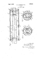
- Fig.' 1 represents a longitudinal, eentral, sectional elevation of a mufier embody ng the invention.
- Figs. 2 and 3 are transverse sectional eleva- "tions thereof on line 2'2, and 3-3, Fig 1.
- This invention may be usedm connectmn with muflers of diflerent types.
- the mulfl'er shown in the drawings for the purpose of i1 lustration ofmyinvention includes an iuner.
- an "intermediate 51611 or tube B of substantially elliptical or other non-circular cross section, having its smallest diameter greater than the dlameter of the inner tube A and arranged substam I as tially concentric with regard to the inner 4,5 erably made of sheet metal and are rovided with shoulders by means of which t e' shells are held in place, the head D havin a shoulde-r '02 for the elliptical shell B an an outer flange or shoulder at" for the outer tube 0,
- head D also has an inwardly extending flange w d which ngages the outer periphery of inner shell A and which is suitably secured to this shell, to form a substantially air tight joint therewith, for example, by means of an inwardly extending bead d ofthe shell A, which cooperates with a bead d on the flange (1
- These beads therefore not only serve to securely hold the inner shell A in place, but in addition, positively insurea tight joint.
- The'inner shell which is connected directly with the exhaust pipe of the engine, is provided with a series of perforations or holes a which are so arranged that the gases passing through these perforations enter into the chamber between the tubes A and Bat the portions thereof of smallest cross section, or
- the gases impingeupon the portions of the elliptical tube B at the minor axis, and pass from the portion oat-the chamber of smaller dimension to those of. greater dimension causing expansion of the gases.
- the elliptical shell B is provided at the portions thereof of greater dimension with a plurality of perforations or holes 6 through which the gases ass into theouter chamber formed by the tu es or shells l3 and G and are further expanded in this chamber by passing from the portions of smaller cross-sectional area to those of greater area.
- the gases are discharged from the outer chamber into the rear endof the inner shell or tube A, which for this purpose is. separated or divided from the front portion'of-the inner tube or shell by means of a partition plate F which may be suitably securedin the 111116? tube, preferably by means ofran' in-" i which enters a l ternally extended bead smaller annular beadjr" on the partition l and is secured by means of spot-welding or. other securin means.
- This partition forms at the rear on of theinner shell A'a dischar e compartment' or space Gr from which t e gases flow out of the'mufller through a discharge pipe or nozzle H.
- this discharge nozzle is secured to an inwardl extending annular flan e it formed on t e head E, the dischargetu e or nozzle H being preferably provided for this f purpose with an expanded bead flangeh which abuts against one side of the flange 72., and the inner ends of the tube or nozzle are turned outwardly against the opposite side oithe flange has indicated at Any other means for securing the discharge nozzle to the mufller may be employed.
- the portions of the'non-circular tube C which extend into closest proximity to the discharge chamber G are provided with holes or perforations adapted to communicate with similar holes or erforations in the discharge chamber G, and in order to form a connection between the outer chamber and the dischargechamber, the portions of the shell B around the perforations therein are pressed inwardly into contact with the shell A, and a suitable connection is made between the shell B and 'dersdande the shell A around the holes therein.
- This connection in the construction shown ismade by bending the metal ofthe shell A around the edges of the perforations in the shell B in such a manner as to form a seam therewith as indicated at I.
- connection between the outer chamber and the discharge chamber G is made in an inexpensive and efiicient manner without necessitating the provision of any additional part other than.
- the shells themselves and the arrangement of the connecting passage is such that the gases flow from the portions of the outer chamber of greatest cross sectional area so that these gases are fully expanded in the outer chamber before they are discharged into the discharge cham-.
- connections from the outer chamber to the discharge chamber are -arranged at opposite sides of the discharge chamber, which causes the two currents of .gas which pass from the outer chamber into the discharge chamber to impinge and thus further deaden any sound or noise.
- the connection between the elongated sides of the elliptical shell B and the inner shell A also serves to hold the portion of the elliptical shell nearthe dischar chamber C from assuming a substantia y circular cross sectional shape when the mufller is subjected to severe internal explosions.
- the heads D and E are provided adjacent to the shoulthereof with which the shell with inwardly extending proections h tially parallel with the shoulders d and a" and engaging the shell.
- the ends of the shell B are preferably turned over, one end of the shell being turned over outwardly to form 'a cult is and the other end being turned inwardly to form a cufl k.
- the portions of the non-circular shell B intermediate of the ends thereof are preferably reinforced against the distorting action of explosions in the mufiler by'means of a bridge or truss member L which surrounds the shell and engages the elongated sides thereof so as to prevent these sides from bending or bulging outwardly.
- this truss member is made of a single stamping of relatively heavy sheet metal and the portions Z of the truss member whichv are adjacent to'the portions of least dimension of the shell B are made of greatest depth and this depth graduall decreases toward those portions of the she I B of greatest dimension.
- the truss member as will be seen in Fig. 2; provides spaces at opposite sides thereof between the outer shell 0 and the shell B through which the gases in the outer chamber may move lengthwise of the shell B towardthe discharge end thereof.
- this s ell may, if desired, be made of thinner ,metal than has heretofore been used without any sacrifice of strength and a mufller may be provided with expansion chambers which are much smaller in cross section at the portions where the gases enter the chambers than at those portions in which the gases leave the chambers which results in very eflicient silencing.
- a mufiler the combination of a plurality of shells of different sizes arranged one 'within another forming a plurality of chambers in which the gases of combustion expand, said shells being provided with openings through which the gases flow from one chamber to another, two adjacent shells being rovided with registering holes and bein nt to cause the portions having said ho es to be brought into contact to as to flow through said holes without mixmg with the gas in the chamber between said two, shells, and means for securing said shells together around said holes.
- portions of the elongated sides of said elliptical shell extendin into proximity to and being connected wit said inner shell and being provided with holes which register with corresponding holes in said inner shell, whereby gases are discharged into said discharge chamber fromopposite sides thereof to form two currents which impinge against.
- a inufiler the combination of a pluralit of shells of different sizes arranged one within another forming a plurality of chambers in which the gases of combustion expand, means ,for permitting gases to flow' from the inner shell toward and a connection between shells to permit ases to flow from 'an' outer shell toward an inner shell without mixing with the gases which are flowing in the opposite direction,
- connection being formed by bending portions of adjacent shells into contact with each other, and perforating and securing together the contacting portions of said shells.
Landscapes
- Engineering & Computer Science (AREA)
- Chemical & Material Sciences (AREA)
- Combustion & Propulsion (AREA)
- Mechanical Engineering (AREA)
- General Engineering & Computer Science (AREA)
- Exhaust Silencers (AREA)
Description
Sept. 4, 1928.
1 R. J. M KENZlE ET AL MUFFLER Filed Dec. 21, 1925 W v W Arm/ways.
Q v v 0%?0066000 w OGQMMUOGOOO R Patented Sept. '4, 1928.
UNITED STATES Pram. caries.
' BOY J. MACKENZIE AND LUCIEN L. HMS, QB BUFFALO, NEW YORK, ASSIGNOBS 1'0 BUFFALO PBESSED STEEL COMPANY, OF IB-U FFALO, NEW YORK.
Application filed December 21, 1925. Serial No. 76,711. r
This invention relates to improvements in inufiiers or silencers of thc'kmd adapted to be used in connection with internal combustion engines.
- 6 fine objects of this invention are to provide a muiiler having a plurality of annular com- 7 partments with means for connecting two annular compartments to permit the gases to flow from one of the compartments to the 0 other across an intermediate compartment;
also to rovide improved means for bracing tubes (i nore-circular cross section in such a manner that such tubes will maintain their correct shape when subjected to severe 1nternal strains; also to improve the construction of mufiers in other respects hereinafter In the accompanying drawings:
Fig.' 1 represents a longitudinal, eentral, sectional elevation of a mufier embody ng the invention.
' Figs. 2 and 3 are transverse sectional eleva- "tions thereof on line 2'2, and 3-3, Fig 1. This invention may be usedm connectmn with muflers of diflerent types. The mulfl'er shown in the drawings for the purpose of i1 lustration ofmyinvention includes an iuner. cylindrical tube or shell.A of substantmlly circular cross section'into which theexhaust so ases pass from ah engine, an "intermediate 51611 or tube B of substantially elliptical or other non-circular cross section, having its smallest diameter greater than the dlameter of the inner tube A and arranged substam I as tially concentric with regard to the inner 4,5 erably made of sheet metal and are rovided= with shoulders by means of which t e' shells are held in place, the head D havin a shoulde-r '02 for the elliptical shell B an an outer flange or shoulder at" for the outer tube 0,
5c and the head E haying shoulders e and 6 en-- gaged res ectively by the shells A and B; and an outer iiange or shoulder e around WhlCh the outer shell G of the mufiler extends. The
head D also has an inwardly extending flange w d which ngages the outer periphery of inner shell A and which is suitably secured to this shell, to form a substantially air tight joint therewith, for example, by means of an inwardly extending bead d ofthe shell A, which cooperates with a bead d on the flange (1 These beads therefore not only serve to securely hold the inner shell A in place, but in addition, positively insurea tight joint.
The'inner shell, which is connected directly with the exhaust pipe of the engine, is provided with a series of perforations or holes a which are so arranged that the gases passing through these perforations enter into the chamber between the tubes A and Bat the portions thereof of smallest cross section, or
in other words, the gases impingeupon the portions of the elliptical tube B at the minor axis, and pass from the portion oat-the chamber of smaller dimension to those of. greater dimension causing expansion of the gases.
The elliptical shell B is provided at the portions thereof of greater dimension with a plurality of perforations or holes 6 through which the gases ass into theouter chamber formed by the tu es or shells l3 and G and are further expanded in this chamber by passing from the portions of smaller cross-sectional area to those of greater area.
The gases are discharged from the outer chamber into the rear endof the inner shell or tube A, which for this purpose is. separated or divided from the front portion'of-the inner tube or shell by means of a partition plate F which may be suitably securedin the 111116? tube, preferably by means ofran' in-" i which enters a l ternally extended bead smaller annular beadjr" on the partition l and is secured by means of spot-welding or. other securin means. This partition forms at the rear on of theinner shell A'a dischar e compartment' or space Gr from which t e gases flow out of the'mufller through a discharge pipe or nozzle H. In the construction shown, this discharge nozzle is secured to an inwardl extending annular flan e it formed on t e head E, the dischargetu e or nozzle H being preferably provided for this f purpose with an expanded bead flangeh which abuts against one side of the flange 72., and the inner ends of the tube or nozzle are turned outwardly against the opposite side oithe flange has indicated at Any other means for securing the discharge nozzle to the mufller may be employed.
lows: The portions of the'non-circular tube C which extend into closest proximity to the discharge chamber G are provided with holes or perforations adapted to communicate with similar holes or erforations in the discharge chamber G, and in order to form a connection between the outer chamber and the dischargechamber, the portions of the shell B around the perforations therein are pressed inwardly into contact with the shell A, and a suitable connection is made between the shell B and 'dersdande the shell A around the holes therein. This connection in the construction shown ismade by bending the metal ofthe shell A around the edges of the perforations in the shell B in such a manner as to form a seam therewith as indicated at I. By means of this construction the connection between the outer chamber and the discharge chamber G is made in an inexpensive and efiicient manner without necessitating the provision of any additional part other than. the shells themselves and the arrangement of the connecting passage is such that the gases flow from the portions of the outer chamber of greatest cross sectional area so that these gases are fully expanded in the outer chamber before they are discharged into the discharge cham-.
ber. Furthermore, the connections from the outer chamber to the discharge chamber are -arranged at opposite sides of the discharge chamber, which causes the two currents of .gas which pass from the outer chamber into the discharge chamber to impinge and thus further deaden any sound or noise. The connection between the elongated sides of the elliptical shell B and the inner shell A also serves to hold the portion of the elliptical shell nearthe dischar chamber C from assuming a substantia y circular cross sectional shape when the mufller is subjected to severe internal explosions.
It'is well known that if a tube of non-circular cross section is subjected to internal explosive pressure, the tendency of this pressure is to change the sha of the tube to a circular cross section. I nsequently the elliptical tube or shell B may, if the mufller is subected to an explosion of sufficient violence,
be changed from its form as shown in the drawings to a form more resembling a shell of circular crosssection, and in. order to avoid distortion of the shell B due to unusually severe explosions in the mufller, the heads D and E are provided adjacent to the shoulthereof with which the shell with inwardly extending proections h tially parallel with the shoulders d and a" and engaging the shell. B. Also the ends of the shell B are preferably turned over, one end of the shell being turned over outwardly to form 'a cult is and the other end being turned inwardly to form a cufl k. These projections K together with the connection I between the shell B and the shell A effectually serve to hold the ends of the shell B against assuming a more or less circular crow section due to internal pressure.
4 The portions of the non-circular shell B intermediate of the ends thereof are preferably reinforced against the distorting action of explosions in the mufiler by'means of a bridge or truss member L which surrounds the shell and engages the elongated sides thereof so as to prevent these sides from bending or bulging outwardly. In the particularconstruction shown this truss member is made of a single stamping of relatively heavy sheet metal and the portions Z of the truss member whichv are adjacent to'the portions of least dimension of the shell B are made of greatest depth and this depth graduall decreases toward those portions of the she I B of greatest dimension. The truss member, as will be seen in Fig. 2; provides spaces at opposite sides thereof between the outer shell 0 and the shell B through which the gases in the outer chamber may move lengthwise of the shell B towardthe discharge end thereof.
By reinforcin the non-circularshell B as described, this s ell, may, if desired, be made of thinner ,metal than has heretofore been used without any sacrifice of strength and a mufller may be provided with expansion chambers which are much smaller in cross section at the portions where the gases enter the chambers than at those portions in which the gases leave the chambers which results in very eflicient silencing.
We claim as our invention:
. 1. In a mufiler, the combination of a plurality of shells of different sizes arranged one 'within another forming a plurality of chambers in which the gases of combustion expand, said shells being provided with openings through which the gases flow from one chamber to another, two adjacent shells being rovided with registering holes and bein nt to cause the portions having said ho es to be brought into contact to as to flow through said holes without mixmg with the gas in the chamber between said two, shells, and means for securing said shells together around said holes.
2; In a mufller, the combination of an inner shell provided with a partition dividin said shellinto an inlet portion and a disc at e chamber, an intermediate and an outer she said intermediate shell being formed so that portions thereof are'in contact with said inner shell adjacent to said discharge chamber, said contacting portions of said inner.
permit 'lll Ill
III
7 having a partition dividing and intermediate shells bein provided-with registering holes, and means or securing said contacting portions of said shells together.
3. In a mufilenthe combination of an inner shell provided wi h a partition dividing said shell into an inlet portion and a'discharge chamber, an intermediate and an outer shell, said intermediate shell being formed so that portions thereof are in contact with said inner shell adjacent to said discharge chamber said contactin ortions of said inner and intermediate s ells being provided with registering holes, the metal surrounding the hole in one of the edges of the hole in the other shell to secure said shells together.
4. Ina mufller, the combinationof inner and outer shells of substantially circular cross section and an intermediate shell of substantially elliptical cross section, the inner shell said inner shell into an inlet portion and a discharge chamber,
portions of the elongated sides of said elliptical shell extendin into proximity to and being connected wit said inner shell and being provided with holes which register with corresponding holes in said inner shell, whereby gases are discharged into said discharge chamber fromopposite sides thereof to form two currents which impinge against.
each other in said chamber.
5. In a inufiler, the combination of a pluralit of shells of different sizes arranged one within another forming a plurality of chambers in which the gases of combustion expand, means ,for permitting gases to flow' from the inner shell toward and a connection between shells to permit ases to flow from 'an' outer shell toward an inner shell without mixing with the gases which are flowing in the opposite direction,
said shells being bent around the outer shell,
said connection being formed by bending portions of adjacent shells into contact with each other, and perforating and securing together the contacting portions of said shells.
6. In a mufller, the combination of shells of circulanand non-circular cross section arranged one within another, and a connection between a circular shell and a portion of a shell of non-circular cross section, said connection being provided for permitting gases to pass from the chamber outside of the outer of said shells to a chamber inside of the inner of said shells and for bracing said shell of non-circular cross section.
7. In a muflier, the combination of inner and outer shells of substantially circular cross section and an intermediate shell of substantially elliptical cross section arranged between the shells of circular cross section,
openings in said inner circular shell adjacent to the portions of said elliptic shell of smallest diameter through which gases may flow from one shell to another: openings in said elliptic shell in the portions thereof of reatest diameter through which gases may ow, where by the ases expand lnside and outside of said elliptic shell by flowing from spaces. of reduced cross sectional area to spaces of increased cross sectional area, a portion 0 said elliptic shellbeing bent toward said inner shell of circular cross section and secured thereto and apertured to establish a communication between the chamber enclosed by said outer shell of circular cross section and the chamber enclosed by said inner shell, whereby gases are discharged from the chamber enclosed by said outer shell at the portions thereof of greatest cross sectional area.
ROY J. MACKENZIE. LUCIEN L. I-IAAS.
Priority Applications (1)
| Application Number | Priority Date | Filing Date | Title |
|---|---|---|---|
| US76711A US1683084A (en) | 1925-12-21 | 1925-12-21 | Muffler |
Applications Claiming Priority (1)
| Application Number | Priority Date | Filing Date | Title |
|---|---|---|---|
| US76711A US1683084A (en) | 1925-12-21 | 1925-12-21 | Muffler |
Publications (1)
| Publication Number | Publication Date |
|---|---|
| US1683084A true US1683084A (en) | 1928-09-04 |
Family
ID=22133736
Family Applications (1)
| Application Number | Title | Priority Date | Filing Date |
|---|---|---|---|
| US76711A Expired - Lifetime US1683084A (en) | 1925-12-21 | 1925-12-21 | Muffler |
Country Status (1)
| Country | Link |
|---|---|
| US (1) | US1683084A (en) |
Cited By (2)
| Publication number | Priority date | Publication date | Assignee | Title |
|---|---|---|---|---|
| US2445045A (en) * | 1944-06-26 | 1948-07-13 | Strachan Christopher | Sound-trapping muffler construction |
| US11698008B2 (en) | 2020-02-14 | 2023-07-11 | Tenneco Automotive Operating Company Inc. | Exhaust device |
-
1925
- 1925-12-21 US US76711A patent/US1683084A/en not_active Expired - Lifetime
Cited By (2)
| Publication number | Priority date | Publication date | Assignee | Title |
|---|---|---|---|---|
| US2445045A (en) * | 1944-06-26 | 1948-07-13 | Strachan Christopher | Sound-trapping muffler construction |
| US11698008B2 (en) | 2020-02-14 | 2023-07-11 | Tenneco Automotive Operating Company Inc. | Exhaust device |
Similar Documents
| Publication | Publication Date | Title |
|---|---|---|
| US1081348A (en) | Exhaust-silencer. | |
| US2065343A (en) | Exhaust muffler | |
| US2958389A (en) | Silencer or muffler | |
| US2019746A (en) | Muffler | |
| US1184431A (en) | Noise-muffler. | |
| US2115128A (en) | Muffler | |
| US2416452A (en) | Muffler | |
| US2473103A (en) | Baffle type muffler | |
| US2235705A (en) | Muffler | |
| US2099887A (en) | Muffler | |
| US1866004A (en) | Muffler | |
| US1993397A (en) | Exhaust conduit and muffler for an automotive vehicle | |
| US2047442A (en) | Muffler | |
| US2099858A (en) | Muffler construction | |
| US1683084A (en) | Muffler | |
| US1924605A (en) | Muffler | |
| US2111537A (en) | Muffler | |
| US2016254A (en) | Muffler | |
| US2073218A (en) | Muffler | |
| US2182204A (en) | Silencing the exhaust of internal combustion engines | |
| US2131001A (en) | Muffler | |
| US1376957A (en) | Exhaust-muffler | |
| US2038309A (en) | Silencer | |
| US2188202A (en) | Muffler | |
| US2083840A (en) | Muffler |