US1681963A - Magnetophone - Google Patents
Magnetophone Download PDFInfo
- Publication number
- US1681963A US1681963A US348935A US34893520A US1681963A US 1681963 A US1681963 A US 1681963A US 348935 A US348935 A US 348935A US 34893520 A US34893520 A US 34893520A US 1681963 A US1681963 A US 1681963A
- Authority
- US
- United States
- Prior art keywords
- diaphragm
- magnetophone
- attached
- armature
- magnet
- Prior art date
- Legal status (The legal status is an assumption and is not a legal conclusion. Google has not performed a legal analysis and makes no representation as to the accuracy of the status listed.)
- Expired - Lifetime
Links
- 239000004020 conductor Substances 0.000 description 2
- 238000010276 construction Methods 0.000 description 2
- 230000000694 effects Effects 0.000 description 2
- 230000033001 locomotion Effects 0.000 description 2
- 239000002184 metal Substances 0.000 description 2
- 241000287181 Sturnus vulgaris Species 0.000 description 1
- 239000008187 granular material Substances 0.000 description 1
- 230000001939 inductive effect Effects 0.000 description 1
- VNWKTOKETHGBQD-UHFFFAOYSA-N methane Chemical compound C VNWKTOKETHGBQD-UHFFFAOYSA-N 0.000 description 1
- 230000007935 neutral effect Effects 0.000 description 1
- 238000012856 packing Methods 0.000 description 1
- 230000000284 resting effect Effects 0.000 description 1
- 230000011664 signaling Effects 0.000 description 1
Images


Classifications
-
- G—PHYSICS
- G01—MEASURING; TESTING
- G01S—RADIO DIRECTION-FINDING; RADIO NAVIGATION; DETERMINING DISTANCE OR VELOCITY BY USE OF RADIO WAVES; LOCATING OR PRESENCE-DETECTING BY USE OF THE REFLECTION OR RERADIATION OF RADIO WAVES; ANALOGOUS ARRANGEMENTS USING OTHER WAVES
- G01S1/00—Beacons or beacon systems transmitting signals having a characteristic or characteristics capable of being detected by non-directional receivers and defining directions, positions, or position lines fixed relatively to the beacon transmitters; Receivers co-operating therewith
- G01S1/72—Beacons or beacon systems transmitting signals having a characteristic or characteristics capable of being detected by non-directional receivers and defining directions, positions, or position lines fixed relatively to the beacon transmitters; Receivers co-operating therewith using ultrasonic, sonic or infrasonic waves
Definitions
- My invention relates to means for receiving sound waves and transmitting them to a suitable indicator, and more especially to .an instrumentfor the receiving of submarine signals, which may be useful to determine the direction from which signals are approaching.
- lt comprises anaperiodic diaphragm, that is, one which has no inherent periodicity, but willrespond equally well to vibrations of any periodicity, to which diaphragm is attached an armature to move positively therewith in a magnetic field, as will be 11nderstood by the description below.
- Fig. 2 is a front elevation.
- Fig. 3 is a top view or plan, the casing being in section.
- Fig. 4 is a section on line 4 4 of Fig. 3.
- Fig. 5 is a vertical section
- Fig. 6 is-a. diagrammatic view showing the use of these parts binaurally.
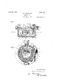
- A is a cup-shaped casing having a flange a to which is attached by screws a ring B. This ring is recessed and to it is attached by screws c and a clamping ring a an aperiodic diaphragm C made preferably of fairly thick soft rubber.
- a gasket al is used to keep the interior of the casing water-tight.
- the casing A has a neck A1 forming with the nut A2 and glandAa and packing a2 a stuffing box through which passes outA the cable lcomprising the leads 2 and 3.
- a permanent horseshoe magnet D To the ring B is also attached by screws d, (Z1, cl2 and suitable set nuts a permanent horseshoe magnet D.
- the poles of this magnet are made separate therefrom for purposes of easy construction.
- Each comprises al flat plate Z3 which is suitably attachedl to a terminal of the magnet. for example, by a screw d1, d2, the two plates being attached to the outer surfaces of the magnet and each having fingers Z4 projecting from the opposing sides of these plates and extending within the area. surrounded by the magnet so as nearly to meet (see especially Figs. 8 and 5). There are in all four fingers, two projecting from each plate.
- E are L-shaped supports of non-magnetic. metal by which the ends of the plates Z3 are supported, (i5 being screws projecting from the ends of the plates and resting 'in suitable grooves in the supports. The screws enable and keep them apart.
- the supports are shaped so as to allow room for the screws F so that the spring f will lie midway between the coils
- an armature ontlapper G To the springs f is attached an armature ontlapper G, the two ends of the armature belng in close proximity to the tips of the fingers' (Z4 so that it is polarized, the tension of the springs f keeping the armature normally midway between the fingers or poles of the permanent magnet.
- the wires 2 and 3 lead to a receiver 7 and in practice two of t-hese instruments are used, each connected to a receiver, the receivers being connected to a headband 8 (see Fig. 6). It is evident that movements of the armature G from its neutral position will create currents in each circuit 1, 3, 6, 4, 2, 7, and hence cause an indication in the receiver.
- the armature G is moved b v a connection such as the wire H between the diaphragm C and the armature.
- an inverted socket piece J is screwed into or otherwise attached to the diaphragm.
- the socket piece has a hole through it through which passes the bolt to which one end of the wire H is attached.
- a nut jl clamps the bolt to the socket. piece.
- vIn determining the direct-ion of a submarine bell or oscillator signal'binaurally by the use of a compensator, it is necessary that two transmitters be employed. one for each ear.
- the two transmitters must be such that they transmit the sound waves in the same phase in which each re ceives them.
- the phase at which the sound is transmitted is not so important as in this case it is the time of arrival of the first of a train of waves which enables the binaural effect to be obtained.
- the iapper type of magnetophone has the advantage that the pull of the magnet does not put any strain on the diaphragm.
- the flapper is attracted equally by the opposing pulls ol the magnet so that it does nottend to turn. It is thus practical to maintain the proper air gap between the flapper and the magnet poleL face.
- the pull of the magnets would strain the rubber diaphragm by drawing in an armature attached to the diaphragm and thus make it impossible to maintain the proper air gap.
- magnetophones may be sub- .stituted for that shown.
- the intensity of thetone receivedlcan be .amplified any desired amount by well known circuit for inducing a current in said electrical circuit.
- a h drophone comprising a casing, a rubber diaphragm mounted in said cas'ng and exposed to receive the approaching sound waves, and electromagnetic means operatedl by the motion of said diaphragm, said electromagnetic means including a current carrying conductor located with relation to said electromagnetic means whereby a current will be directly induced in said conductor.
Landscapes
- Engineering & Computer Science (AREA)
- Computer Networks & Wireless Communication (AREA)
- Physics & Mathematics (AREA)
- General Physics & Mathematics (AREA)
- Radar, Positioning & Navigation (AREA)
- Remote Sensing (AREA)
- Transducers For Ultrasonic Waves (AREA)
Description
.-1920 5 Sheets-Sheet 1 RL L. WILLIAMS MAGNETOPHONE Filed Jan. 2
Aug. 28, wm www@ R. L. WILLEAMS MAGNETOPHONE Filed Jan. 2 1920 5 Sheets-Sheet 2 ugz 289 lgZ.
R. L. WILLBAMS MAGNETOPHONE Fil Jan, 2, 1920 5 Sheets-Sheet 5 ffm 40. 74M
www
7' raaf/fyi Patented ug. 28, 192%.
autres stares etaient FEENT ROBERT L. VTILLIAMS, OF NEWTON, MASSACHUSETTS, ASSG-NOR TO SUBMARINE SIGNAL CCIVIPANY, 0F PORTLAND, MAINE, A CORPORATION 0F MANE.
ivraennrornonn;
Application filed January 2, 1920. Serial No. 848,935.
My invention relates to means for receiving sound waves and transmitting them to a suitable indicator, and more especially to .an instrumentfor the receiving of submarine signals, which may be useful to determine the direction from which signals are approaching.
lt comprises anaperiodic diaphragm, that is, one which has no inherent periodicity, but willrespond equally well to vibrations of any periodicity, to which diaphragm is attached an armature to move positively therewith in a magnetic field, as will be 11nderstood by the description below.
My invention in its preferred form is shown in the drawings, in which" l Figure 1 is a section on line 1-1 of Fig. 5.
Fig. 2 is a front elevation.
Fig. 3 is a top view or plan, the casing being in section.
Fig. 4 is a section on line 4 4 of Fig. 3.
Fig. 5 is a vertical section, and
Fig. 6 is-a. diagrammatic view showing the use of these parts binaurally.
A is a cup-shaped casing having a flange a to which is attached by screws a ring B. This ring is recessed and to it is attached by screws c and a clamping ring a an aperiodic diaphragm C made preferably of fairly thick soft rubber. A gasket al is used to keep the interior of the casing water-tight.
,The casing A has a neck A1 forming with the nut A2 and glandAa and packing a2 a stuffing box through which passes outA the cable lcomprising the leads 2 and 3.
To the ring B is also attached by screws d, (Z1, cl2 and suitable set nuts a permanent horseshoe magnet D. The poles of this magnet are made separate therefrom for purposes of easy construction. Each comprises al flat plate Z3 which is suitably attachedl to a terminal of the magnet. for example, by a screw d1, d2, the two plates being attached to the outer surfaces of the magnet and each having fingers Z4 projecting from the opposing sides of these plates and extending within the area. surrounded by the magnet so as nearly to meet (see especially Figs. 8 and 5). There are in all four fingers, two projecting from each plate.
E are L-shaped supports of non-magnetic. metal by which the ends of the plates Z3 are supported, (i5 being screws projecting from the ends of the plates and resting 'in suitable grooves in the supports. The screws enable and keep them apart.
4 and 5.
the supportsand plates to be clamped together. There are two of these supports, one attached to each plate, and the screws attached to one plate rest in the grooves on .ouit with wires 2 and 3. Pins al projecting from the plates d3 lie between the two coils Thesupports E serve also to carry a leaf spring f attached thereto by screws F. For
this purpose the supports are shaped so as to allow room for the screws F so that the spring f will lie midway between the coils To the springs f is attached an armature ontlapper G, the two ends of the armature belng in close proximity to the tips of the fingers' (Z4 so that it is polarized, the tension of the springs f keeping the armature normally midway between the fingers or poles of the permanent magnet.
The wires 2 and 3 lead to a receiver 7 and in practice two of t-hese instruments are used, each connected to a receiver, the receivers being connected to a headband 8 (see Fig. 6). It is evident that movements of the armature G from its neutral position will create currents in each circuit 1, 3, 6, 4, 2, 7, and hence cause an indication in the receiver.
The armature G is moved b v a connection such as the wire H between the diaphragm C and the armature. As shown, an inverted socket piece J is screwed into or otherwise attached to the diaphragm. The socket piece has a hole through it through which passes the bolt to which one end of the wire H is attached. A nut jl clamps the bolt to the socket. piece. Thus each vibration of the diaphragm, however small, will be communicated to the armature, moving it and exciting a current in the circuit which operates the receiver in the ear piece.
vIn determining the direct-ion of a submarine bell or oscillator signal'binaurally by the use of a compensator, it is necessary that two transmitters be employed. one for each ear. The two transmitters, however. must be such that they transmit the sound waves in the same phase in which each re ceives them.
In determining the direction of propeller los noises which are not musical, the phase at which the sound is transmitted is not so important as in this case it is the time of arrival of the first of a train of waves which enables the binaural effect to be obtained.
Butv with a musical note I have found that the phase isiimportant as all the sound waves are alike andit is difficult to distinguish the time of arrival of the first of the train of waves.
On this account mfcrophones will not always work binaurally listening to a musical note. This is because the microphone buttons do not always produce current in phase with the sound waves. For instance, two microphone buttons may be under the compressional effect of the same sound wave and one gives an increase of current while the other gives a decrease at the same instant. vMoreover it is very difficult to secure two microphones which are exactly 'of the same standard because whereas they may each con- ,tain the same weight of carbon granules, the position'of these granules will never be exactly the same position in the two microphones and hence at a given moment the resistance of the two microphones will not be alike. It is very desirable, if not necessary, that when two receivers are to be used in a binaural system they should be of such character that they will transmit the sounds received with equal efficiency to the ear pieces or other indicators.
Magnetophones, however, because of their construction dovnot have these faults, for it 1 will be seen that when a sound wave strikes the rubber diaphragms they both defiect the fiappers of the magnetophones in the same direction and produce currents fiowing in phase with each other. l
By the use of rubber for the diaphragm, I eliminate the'trouble caused by the residual pitch of a metal diaphragm.
When listening to the same musical note, I find that if the transmitters have diaphragins of different resdual pitch, the notes heard= diaphragms tuned exactly to the pitch of the signal, a diaphragm adapted for a high pitched bell signal would not be suitable for a low pitched oscillator signal. Also, it is difficult to produce diaphragms commercially all of exactly the same pitch and maintain them so in service. A rubber diaphragm does not have these objectionable features and reproduces the note of bell or other signaling device in perfect phase.
The iapper type of magnetophone has the advantage that the pull of the magnet does not put any strain on the diaphragm. The flapper is attracted equally by the opposing pulls ol the magnet so that it does nottend to turn. It is thus practical to maintain the proper air gap between the flapper and the magnet poleL face. iVith the ordinary type of telephone receivers, the pull of the magnets would strain the rubber diaphragm by drawing in an armature attached to the diaphragm and thus make it impossible to maintain the proper air gap.
Other forms of magnetophones may be sub- .stituted for that shown.
The intensity of thetone receivedlcan be .amplified any desired amount by well known circuit for inducing a current in said electrical circuit.
2. A h drophone comprising a casing, a rubber diaphragm mounted in said cas'ng and exposed to receive the approaching sound waves, and electromagnetic means operatedl by the motion of said diaphragm, said electromagnetic means including a current carrying conductor located with relation to said electromagnetic means whereby a current will be directly induced in said conductor.
3. In combination a magnetophone and a diaphragml for receiving sound waves, said diaphragm being aperiodic, said magnetophone and said diaphragm being located in relation to each other and positively connected whereby the vibrations of the diaphragm willbe communicated vto the armature of the magnetophone and set up therein lvibrations corresponding to the vibrations of said diaphragm.
4. In combination a plurality of magnetophones, diaphragms .for receiving sound waves, said diaphragms being aperiodic. a telephone head set, and means for transmitting binaurally the electric impulses ot said soun'd waves to the respective telephones of; said head set whereby a binaural image is obtained, each diaphragm being operatively connected to its magnetophone whereby it will communicate its vibrations thereto ROBERT L. WILLIAMS,
Priority Applications (1)
| Application Number | Priority Date | Filing Date | Title |
|---|---|---|---|
| US348935A US1681963A (en) | 1920-01-02 | 1920-01-02 | Magnetophone |
Applications Claiming Priority (1)
| Application Number | Priority Date | Filing Date | Title |
|---|---|---|---|
| US348935A US1681963A (en) | 1920-01-02 | 1920-01-02 | Magnetophone |
Publications (1)
| Publication Number | Publication Date |
|---|---|
| US1681963A true US1681963A (en) | 1928-08-28 |
Family
ID=23370205
Family Applications (1)
| Application Number | Title | Priority Date | Filing Date |
|---|---|---|---|
| US348935A Expired - Lifetime US1681963A (en) | 1920-01-02 | 1920-01-02 | Magnetophone |
Country Status (1)
| Country | Link |
|---|---|
| US (1) | US1681963A (en) |
Cited By (1)
| Publication number | Priority date | Publication date | Assignee | Title |
|---|---|---|---|---|
| US2452570A (en) * | 1933-05-05 | 1948-11-02 | Submarine Signal Co | Compressional wave transmitting and receiving device |
-
1920
- 1920-01-02 US US348935A patent/US1681963A/en not_active Expired - Lifetime
Cited By (1)
| Publication number | Priority date | Publication date | Assignee | Title |
|---|---|---|---|---|
| US2452570A (en) * | 1933-05-05 | 1948-11-02 | Submarine Signal Co | Compressional wave transmitting and receiving device |
Similar Documents
| Publication | Publication Date | Title |
|---|---|---|
| US1573739A (en) | Telephonic device | |
| US1568589A (en) | Loud speaker | |
| US1681963A (en) | Magnetophone | |
| US1863840A (en) | Loud speaker apparatus and methods | |
| US2069254A (en) | Sound apparatus | |
| US2432424A (en) | Electromagnetic sound translating device | |
| US1105924A (en) | Telephone. | |
| US1984383A (en) | Underwater transmitter and receiver | |
| US1525182A (en) | Sound transmitter and receiver | |
| US1753812A (en) | Loud-speaking telephone receiver | |
| US1051113A (en) | Telephone. | |
| US1679194A (en) | Radio receiving apparatus | |
| US2031678A (en) | Dynamic microphone | |
| US245919A (en) | de forest | |
| US1689788A (en) | Sound-reproducing instrument | |
| US683953A (en) | Telephone-transformer. | |
| US1526181A (en) | Sound-producing instrument | |
| US1635390A (en) | Electric sound reproducer | |
| US1666262A (en) | Sound transmitter | |
| US766821A (en) | Telephone-transmitter. | |
| US1847935A (en) | Sound control apparatus | |
| US227736A (en) | Electric telephone | |
| GB221586A (en) | Improvements in sound receiving devices | |
| GB267742A (en) | Improvements in and relating to apparatus for transmitting or reproducing sound | |
| GB1206917A (en) | Electroacoustic transducer |