US1676430A - Flush-valve float for flush tanks - Google Patents
Flush-valve float for flush tanks Download PDFInfo
- Publication number
- US1676430A US1676430A US59368A US5936825A US1676430A US 1676430 A US1676430 A US 1676430A US 59368 A US59368 A US 59368A US 5936825 A US5936825 A US 5936825A US 1676430 A US1676430 A US 1676430A
- Authority
- US
- United States
- Prior art keywords
- flush
- valve float
- float
- flush valve
- tanks
- Prior art date
- Legal status (The legal status is an assumption and is not a legal conclusion. Google has not performed a legal analysis and makes no representation as to the accuracy of the status listed.)
- Expired - Lifetime
Links
- 229920001875 Ebonite Polymers 0.000 description 7
- XLYOFNOQVPJJNP-UHFFFAOYSA-N water Substances O XLYOFNOQVPJJNP-UHFFFAOYSA-N 0.000 description 4
- 230000004048 modification Effects 0.000 description 2
- 238000012986 modification Methods 0.000 description 2
- 210000002445 nipple Anatomy 0.000 description 1
- 230000000284 resting effect Effects 0.000 description 1
Images

Classifications
-
- E—FIXED CONSTRUCTIONS
- E03—WATER SUPPLY; SEWERAGE
- E03D—WATER-CLOSETS OR URINALS WITH FLUSHING DEVICES; FLUSHING VALVES THEREFOR
- E03D1/00—Water flushing devices with cisterns ; Setting up a range of flushing devices or water-closets; Combinations of several flushing devices
- E03D1/30—Valves for high or low level cisterns; Their arrangement ; Flushing mechanisms in the cistern, optionally with provisions for a pre-or a post- flushing and for cutting off the flushing mechanism in case of leakage
- E03D1/34—Flushing valves for outlets; Arrangement of outlet valves
Definitions
- My invention relates to improvements in flush valve floats for flush tanks.
- the object of my invention is to provide a hard rubber flush valve float for flush tanks 5 or other purposes, in which the same is made of hard rubber, whereby the operating rod may be attached and provided with a soft horizontal portion adapted to cooperate with the seat so that a smaller seating surface is provided, and thus insure a perfect seating of the valve to prevent leakage of water therearound.
- Another object of my invention is to provide a flush valve float of this character in which means is provided for readily and securely attaching a soft rubber seating surface thereto.
- a further object of my invention is to provide a simple, cheap and eflective flush ball of this character having certain details of structure and combination of parts here inafter more fully set forth.
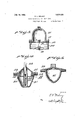
- Figure l is a vertical. sectional view of the discharge pipe and the flush tank showing my improved flush valve float seated thereon.
- Figure 2 is an enlarged sectional view of my improved flush valve float.
- Figure 3 is an enlarged vertical sectional view of a modified form of flush valve float.
- Figure 4 is a vertical sectional view of another modified form of flush valve float.
- Figure 5 is a vertical sectional view of a zltill further modified form of flush valve oat.
- 1 represents the flush tank and 2 the discharge pipe therefrom, which is provided with the usual by-pass 3, to which is connected the pipe 4, leading up into the tank and forms an overflow in the event that the'inlet valve does not properly close.
- the discharge pipe 2 is provided with an annular valve seat 5, of a curved form adapted to cooperate with my improved flush valve float ball which I will now proceed to describe.
- the flush ball 6, as shown in Figure 2 of the drawings is preferably of the form shown, having the slightly conical shaped portion 7, so as to form a guide, whereby the flush float ball is guided down into the discharge pipe 2, due to the suction therein caused by the discharge of water therethrough.
- the flush float ball as shown is made of hard rubber extends through the flush pipe 20.
- DELANY REALTY COR- has its upper end provided with the upwardly extending nipple '8 having a screw threaded opening 9 having screwed therein guide 11, supported by I the operating rod 10 which'extends upwardly sid'erable distance outwardly and to the lower face of which isvulcanized an annular gasket 14 of soft rubber, and whereby the same is rigidly held by the flush ball.
- the inner edge 15 of the gasket 14 could also be vulcanized to the body of the flush ball, although this is not necesssary.
- the flush valve float is provided with an annular groove 25 having its outer periphery 26 threaded above the groove and upon which is screwed the hard rubber ring 27 having a flange 28 supporting the soft rubber gasket 29, and saidisoft rubber gasket 29 having a downwardly extending flange 30 resting upon the groove 25.
- the flush valve'float 31 is of the general'formr shown in Figure 2 of the drawings and is provided with a horizontal soft. rubber flange 32 which may be formed'integral with the flush valve float or made of a separate part, vulcanized or otherwise secured thereto.
- a flush valve float comprising a hollow body portion of hard rubber having ahorizontal annular flange, and a seating surface vulcanized to the lowerface of said flange.
- a flush valve float comprising a hollow hard rubber body portion having its upper end provided with a threaded recess to receive the operating rod and its lower end shaped to guide the same between the valve seat, a horizontal integral flange carried by the body portion, and a soft rubber seating surface vulcanized to the lower face of said flange.
Landscapes
- Health & Medical Sciences (AREA)
- Life Sciences & Earth Sciences (AREA)
- Engineering & Computer Science (AREA)
- Hydrology & Water Resources (AREA)
- Public Health (AREA)
- Water Supply & Treatment (AREA)
- Sanitary Device For Flush Toilet (AREA)
Description
"Jury 10,1928.
E. L. DELANY FLUSH VALVE FLOAT FOR FLUSH TANKS I I Filed Sept. 29, 1925 2 Sheets-Sheet 1 July 10, 1928. I
E. L. DELANY FLUSH VALVE FLOAT ,FOR FLUSH TANKS Filed Sept. 29, 1925 2 Sheets-Sheet 2 Patented July 10, 1928.
UNITED STATESP'ATENT-OFF EDWARD L. DELANY, on nnooxnvn, vnw Yonmnssrenon 'ro PORATION, or BROOKLYN, NEW YoRK.
licn
Application filed September 29, 1925. ,Serial No. 59,368. I
My invention relates to improvements in flush valve floats for flush tanks.
The object of my invention is to provide a hard rubber flush valve float for flush tanks 5 or other purposes, in which the same is made of hard rubber, whereby the operating rod may be attached and provided with a soft horizontal portion adapted to cooperate with the seat so that a smaller seating surface is provided, and thus insure a perfect seating of the valve to prevent leakage of water therearound.
Another object of my invention is to provide a flush valve float of this character in which means is provided for readily and securely attaching a soft rubber seating surface thereto.
A further object of my invention is to provide a simple, cheap and eflective flush ball of this character having certain details of structure and combination of parts here inafter more fully set forth.
In the accompanying drawings Figure l is a vertical. sectional view of the discharge pipe and the flush tank showing my improved flush valve float seated thereon.
Figure 2 is an enlarged sectional view of my improved flush valve float.
Figure 3 is an enlarged vertical sectional view of a modified form of flush valve float.
Figure 4 is a vertical sectional view of another modified form of flush valve float.
Figure 5 is a vertical sectional view of a zltill further modified form of flush valve oat.
Referring now to the drawings, 1 represents the flush tank and 2 the discharge pipe therefrom, which is provided with the usual by-pass 3, to which is connected the pipe 4, leading up into the tank and forms an overflow in the event that the'inlet valve does not properly close. The discharge pipe 2 is provided with an annular valve seat 5, of a curved form adapted to cooperate with my improved flush valve float ball which I will now proceed to describe. The flush ball 6, as shown in Figure 2 of the drawings is preferably of the form shown, having the slightly conical shaped portion 7, so as to form a guide, whereby the flush float ball is guided down into the discharge pipe 2, due to the suction therein caused by the discharge of water therethrough. The flush float ball as shown, is made of hard rubber extends through the flush pipe 20.
DELANY REALTY COR- and has its upper end provided with the upwardly extending nipple '8 having a screw threaded opening 9 having screwed therein guide 11, supported by I the operating rod 10 which'extends upwardly sid'erable distance outwardly and to the lower face of which isvulcanized an annular gasket 14 of soft rubber, and whereby the same is rigidly held by the flush ball. The inner edge 15 of the gasket 14 could also be vulcanized to the body of the flush ball, although this is not necesssary.
By this structure it will be seen that I have produced a hard rubber flush valve float for flush tanks in which-a horizontal annular soft rubber seating surface is pro-- vided', adapted to cooperate with the seat of the discharge pipe 2, whereby the seat of the flush valve float is adapted to seat itself and entirely cut off the flow of water from the discharge pipe. By this arrangement it will be seen that a very small seating surface is provided which lessens the liability of any dirton the seat from preventing the flush valve float from properly seating itself and cutting off the flow of water through the rubber gasket 18. In this form the lifting rod 19 is attached to the lower flat face and In the modification shown in Figure 4, the flush valve float 21 is provided with a central opening 22 therethrough, and the lifting rod 23 has a chain connection 24 with the float. In this form the flush valve float is provided with an annular groove 25 having its outer periphery 26 threaded above the groove and upon which is screwed the hard rubber ring 27 having a flange 28 supporting the soft rubber gasket 29, and saidisoft rubber gasket 29 having a downwardly extending flange 30 resting upon the groove 25. By this structure it will be seen that I have provided means whereby the soft rubber gasket 29 may be replaced at any time.
In the modification shown in Figure 5 the flush valve'float 31 is of the general'formr shown in Figure 2 of the drawings and is provided with a horizontal soft. rubber flange 32 which may be formed'integral with the flush valve float or made of a separate part, vulcanized or otherwise secured thereto.
WVhile I have shown this applied to a flush tank it will be understood that the same could'be used in many other places.
'Havingthus'fully described my invention i what I claim is:
1. A flush valve float comprising a hollow body portion of hard rubber having ahorizontal annular flange, and a seating surface vulcanized to the lowerface of said flange.
2. A flush valve float comprising a hollow hard rubber body portion having its upper end provided with a threaded recess to receive the operating rod and its lower end shaped to guide the same between the valve seat, a horizontal integral flange carried by the body portion, and a soft rubber seating surface vulcanized to the lower face of said flange.
In testimony whereof, I have signed this specification. o
EDWARD L. DELANY.
Priority Applications (1)
| Application Number | Priority Date | Filing Date | Title |
|---|---|---|---|
| US59368A US1676430A (en) | 1925-09-29 | 1925-09-29 | Flush-valve float for flush tanks |
Applications Claiming Priority (1)
| Application Number | Priority Date | Filing Date | Title |
|---|---|---|---|
| US59368A US1676430A (en) | 1925-09-29 | 1925-09-29 | Flush-valve float for flush tanks |
Publications (1)
| Publication Number | Publication Date |
|---|---|
| US1676430A true US1676430A (en) | 1928-07-10 |
Family
ID=22022509
Family Applications (1)
| Application Number | Title | Priority Date | Filing Date |
|---|---|---|---|
| US59368A Expired - Lifetime US1676430A (en) | 1925-09-29 | 1925-09-29 | Flush-valve float for flush tanks |
Country Status (1)
| Country | Link |
|---|---|
| US (1) | US1676430A (en) |
Cited By (2)
| Publication number | Priority date | Publication date | Assignee | Title |
|---|---|---|---|---|
| US2460114A (en) * | 1945-03-29 | 1949-01-25 | Warren B Zern | Tank flush ball and guide support |
| US2705542A (en) * | 1950-08-07 | 1955-04-05 | Yavitch Morris | Shower drain |
-
1925
- 1925-09-29 US US59368A patent/US1676430A/en not_active Expired - Lifetime
Cited By (2)
| Publication number | Priority date | Publication date | Assignee | Title |
|---|---|---|---|---|
| US2460114A (en) * | 1945-03-29 | 1949-01-25 | Warren B Zern | Tank flush ball and guide support |
| US2705542A (en) * | 1950-08-07 | 1955-04-05 | Yavitch Morris | Shower drain |
Similar Documents
| Publication | Publication Date | Title |
|---|---|---|
| US2325956A (en) | Device for preventing backflow in liquid-carrying lines | |
| US2395906A (en) | Antisiphonic plumbing unit | |
| US3107747A (en) | Closet tank fittings with silencing means | |
| US2175973A (en) | Flush tank valve | |
| US2372848A (en) | Toilet tank outlet fitting and elbow | |
| US1676430A (en) | Flush-valve float for flush tanks | |
| US1606274A (en) | Tank-filling valve | |
| US2049909A (en) | Drain trap valve | |
| US2139862A (en) | Guide for valves for flush tanks | |
| US3211172A (en) | Closet tank fittings | |
| US1712605A (en) | Flush-valve float for flush tanks | |
| US2252078A (en) | Venting device for water closet valve mechanisms | |
| US2046792A (en) | Nonsiphoning float valve | |
| US1528098A (en) | Flush-valve-bulb guide | |
| CN110117978B (en) | Water inlet valve for toilet cistern | |
| US2155902A (en) | Tank ball valve | |
| US1925748A (en) | Flush tank valve | |
| US2135231A (en) | Attachment for flush-tank valves | |
| US2096844A (en) | Combination valve and vent for plumbing fixtures | |
| US1077457A (en) | Valve for flush-tanks. | |
| US1624234A (en) | Flush-tank ball seat | |
| US827716A (en) | Flushing-tank. | |
| US2158452A (en) | Tank valve | |
| US3120855A (en) | Anti-siphon ball cock assembly | |
| US2179309A (en) | Close connected water closet combination |