US1664080A - Ornamental iron stair-rail structure - Google Patents
Ornamental iron stair-rail structure Download PDFInfo
- Publication number
- US1664080A US1664080A US107087A US10708726A US1664080A US 1664080 A US1664080 A US 1664080A US 107087 A US107087 A US 107087A US 10708726 A US10708726 A US 10708726A US 1664080 A US1664080 A US 1664080A
- Authority
- US
- United States
- Prior art keywords
- bars
- notches
- angular
- mentioned
- stair
- Prior art date
- Legal status (The legal status is an assumption and is not a legal conclusion. Google has not performed a legal analysis and makes no representation as to the accuracy of the status listed.)
- Expired - Lifetime
Links
- XEEYBQQBJWHFJM-UHFFFAOYSA-N Iron Chemical compound [Fe] XEEYBQQBJWHFJM-UHFFFAOYSA-N 0.000 title description 8
- 229910052742 iron Inorganic materials 0.000 title description 3
- 238000010276 construction Methods 0.000 description 4
- 230000001154 acute effect Effects 0.000 description 2
- 101150071434 BAR1 gene Proteins 0.000 description 1
- 239000000463 material Substances 0.000 description 1
- 230000000284 resting effect Effects 0.000 description 1
- 239000007787 solid Substances 0.000 description 1
- 238000003466 welding Methods 0.000 description 1
Images
Classifications
-
- E—FIXED CONSTRUCTIONS
- E04—BUILDING
- E04F—FINISHING WORK ON BUILDINGS, e.g. STAIRS, FLOORS
- E04F11/00—Stairways, ramps, or like structures; Balustrades; Handrails
- E04F11/18—Balustrades; Handrails
- E04F11/181—Balustrades
- E04F11/1817—Connections therefor
- E04F11/1834—Connections therefor with adjustable angle, e.g. pivotal connections
Definitions
- ROBERT L. uarson, or LOS memes, cALIronmA ROBERT L. uarson, or LOS memes, cALIronmA.
- My invention relatesto an ornamental iron stair rail structure, more particularly to the means of securing the separate members of the side railing of stairs together, and the objects of my invention are: first, to provlde a'stair-rail structure of this class in which the separate members are rigidly secured together withoutwelding, riveting or the like; second, to provide a stair rail structure of this class in which the vertical bar members are provided with recess portions made by a and which will not readily deteriorate or get out of order.
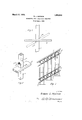
- Figure 1 is a side elevational 'view of the vertical and angular bars showing by solid lines the position. of the angular bar at approximately a right angle tothe perpendicular bar before being secured rigidly together, and showing by 'dotted lines the angular position of the bar when the members are rigidly secured in position and ready for use.
- Figure 2 is a perspective view of the vertical and angular bars vwith the angular bars shown slightly below the position in which they are securely positioned
- Fig' ure 3 is a fragmentary side elevational view of a stair rail constructed of a plurality of the perpendicular and angular bars in their assembled position.
- the vertical bars 1. are preferably made of square material about one-half inch square.
- the angular bars 2 are preferably about one-quarter 4'?) by one (1'1) or one and one-quarter (1%") lnches and they are provided with square holes 2 which holes are made to conform to a cross-section of the bar 1 In this case it is shownsquare and is slightly larger than the bar so that the bars 2 will readily slide over the bar- 1; and the upper innercorner of the walls surrounding the hole 2' is adapted to fit into the notch 1 and the lower .inner corner is adapted to fit into the notch 1 in the bar 1 when the member 2.
- annular members 4 may be interposed between theseparate members 1 and 2 and resting against said members as shown in Figure 3 of the drawings.
- second mentioned bars being inclined at an acute angle relatively to said first mentioned bars whereby said bars are interlocked rela- 3.
- a plurality of bars provided with pairs of angular notches positioned in opposite sides of said bars, the one slightly above the other, and a plurality of other barsnconnecting each of the former mentionedb ars the wall.
- a plurality of] square, perpendicular members provided with a plurality of pairs of spaced notches in opposite sides thereof andwebs in said notches, and a plurality of spaced bars provided With holes adapted to fit. loosely oversaid'perpendicular bars and 'fit in said notches andto crush said webs when turned to an angular position on said bars, and
Landscapes
- Engineering & Computer Science (AREA)
- Architecture (AREA)
- Civil Engineering (AREA)
- Structural Engineering (AREA)
- Steps, Ramps, And Handrails (AREA)
Description
March 27, 1928;
R. L. MAPSON ORNAMENTAL IRON STAIR RAIL STRUCTURE grmwuhw ROBERT L MAPSO/V Filed May 6. 1926 Fatented Mar. 27, 19 28.
" i I I 1,664,080"
UNITED STATES PATENT OFFICE.
ROBERT L. uarson, or LOS memes, cALIronmA.
QRN'AMENTAL IRON STAIR--BA IL STRUCTURE.
Application'filed May 6,1926. Serial No. 107,0 8).
- My invention relatesto an ornamental iron stair rail structure, more particularly to the means of securing the separate members of the side railing of stairs together, and the objects of my invention are: first, to provlde a'stair-rail structure of this class in which the separate members are rigidly secured together withoutwelding, riveting or the like; second, to provide a stair rail structure of this class in which the vertical bar members are provided with recess portions made by a and which will not readily deteriorate or get out of order.
With these and other objects in view as my invention con will appear hereinafter, sists of certain novel features of construction, combination and arrangementof parts and portions as will be hereinafter described in detail and particularly set forthin the appended claims, reference being had to the accompanying drawings and to the characters'of reference thereon which form a part of this application in which:
Figure 1 is a side elevational 'view of the vertical and angular bars showing by solid lines the position. of the angular bar at approximately a right angle tothe perpendicular bar before being secured rigidly together, and showing by 'dotted lines the angular position of the bar when the members are rigidly secured in position and ready for use. Figure 2 is a perspective view of the vertical and angular bars vwith the angular bars shown slightly below the position in which they are securely positioned, and Fig' ure 3 is a fragmentary side elevational view of a stair rail constructed of a plurality of the perpendicular and angular bars in their assembled position.
Similar characters of reference refer to similar parts and portions throughout the several views of the drawings.
Thevertical bars -1, and angular bars 2,
constitute the principal'parts and portions I of my ornamental iron structure. The vertical bars 1. are preferably made of square material about one-half inch square.
desired. Theyare each provided in opposite sides with notches 1 and 1 which are preferably made by a punch press. It will be noted that on the one side there is a thin oo However, they may be polygon shaped 1f,-
web providing for a-rigid, tight fit of the members 1 and 2relatively to each other where there is slight variation between the various steps of the stairs.
g It will be noted that the upper member 2 as shown'in Figure 3 of the drawingfits on the upper end of theuprights 1. Therefore the upper notch 1 is not complete, the upper portion being cut off Then over the upper member 2 is, provided a cover member 3 for covering the upper end. The lower end of the upright ordinarily restsupon the end of the steps of the stairs as shown best'in. Figure 3 of the drawing. When assembling this structure a plurality of the uprights 1 are placed in the holes 2of a plurality of the angular bars 2 positioned adjacent the notches 1 and 1 in spaced relation. Then the structure is forced to the angular position by raising the ends of the bars 2 rela tively to the bars 1 and the bars 2interlocking with the barsl asshown in Figure 3 of the drawing, and by dotted lines in Figure 1 of the drawings, after which they are secured at their ends, providing a rigid interlocking ornamental iron structure without welding, riveting or the like. i
In order to furthersupport the structure annular members 4 may be interposed between theseparate members 1 and 2 and resting against said members as shown in Figure 3 of the drawings.
Though I have shown and described aparticular construction, combination and arrangement of parts and portions, I do not wish to be liini-ted'to this particular construction, combination and arrangement but desire to include in the scope of my invention the construction, combination and arrangement substantially as set forth in the appended claims.
Having thus described my invention, what I claim as new and desire to secure by Letters Patent is: '1 In a structure of the class described, a plurality of polygon cross section bars pro;- vided with pairs of angular notches in "opposite sides of said bars and a plurality of 7 other bar s connecting each of the former and V tively to each other.
v gle thereto.
provided with holes therethrough of substantially the same cross-section as the crosssection of said first mentioned bars between the opposed notches thereof and adapted to fit over said latterbars and fit in the notches insaid first mentioned bars, the transverse axis of the last mentioned bars being at a right angle to the first mentioned bars and the longitudinal axis being at an acute an- 2. In a stair side rail, a provided with pairs of angular notches positioned in opposite sides of said bars, the
one slightly above the other, and a plurality of other bars connecting'each of the former and provided with holes there- 'through conforming to the cross section of said first mentionedbars the wall surrounding said holes in said second mentioned bars being adapted to fit in the notches in the first "mentioned bars, the longitudinal axis of said.
second mentioned bars being inclined at an acute angle relatively to said first mentioned bars whereby said bars are interlocked rela- 3. In a stair side rail, a plurality of bars provided with pairs of angular notches positioned in opposite sides of said bars, the one slightly above the other, and a plurality of other barsnconnecting each of the former mentionedb ars the wall. surrounding said holes in said second mentioned bars being adapted to fit in the notches inthe first mentioned bars, said second mentioned bars being fitted to an angle relatively to said first mentioned bars whereby said bars are I plurality of bars" interlocked relatively toeach other, and a former and provided with holes there-- through conforming to the cross section of said first mentioned bars the wall surround mg said holes in said second mentioned bars being adapted to fit in the notches in the first mentioned bars, said second mentioned 'ba'rs being fitted to an angle relatively to said first mentioned bars whereby said bars are interlocked relatively to each other, a
web positioned at the end of one of said' notches adapted to be engaged by the corner of the wall'of the second mentioned bars, a
and means interposed between saidjfirst mentioned bars and the second mentioned bars'for holding said bars in rigid spaced relation to eachother,
5. In. a structure of the class described, a
plurality of square upright bars in spaced relationwith each other, each provided with pairs of'oppo'sitely' disposed angular notches in said upright bars, and a plurality of angular bars positionedwith theirlongitudinal axes at a'cute'angles with the former and 1 provided with holes therethrough conforrning to the cross-section of said ang'ularbars at said notches and adapted'to fitj over same and when moved to longitudinal angular position to fit inthei 'not ch es in said first men-f tioned bars.'
6. In a stair rail of the class described, a
plurality of square, perpendicular members, provided with a plurality of pairs of spaced notches in opposite sides thereof-and webs in:
said notches, and a plurality of spaced bars provided with holes adapted to. fit. loosely over said perpendicular bars andfit in said notches and to crush said webs when turned to an angular position on said, .bars.
7.In a stair rail of the class described, a plurality of] square, perpendicular members, provided witha plurality of pairs of spaced notches in opposite sides thereof andwebs in said notches, and a plurality of spaced bars provided With holes adapted to fit. loosely oversaid'perpendicular bars and 'fit in said notches andto crush said webs when turned to an angular position on said bars, and
means interposed between said perpendicular and angular bars for holding said bars in separate spaced relation and rigidly securing them together. r
In testimony whereof, I-have hereunto set my handat Los Angeles, California, this 7 f 29th day of April, 1926.
ROBERT L. MAPSYON.
Priority Applications (1)
| Application Number | Priority Date | Filing Date | Title |
|---|---|---|---|
| US107087A US1664080A (en) | 1926-05-06 | 1926-05-06 | Ornamental iron stair-rail structure |
Applications Claiming Priority (1)
| Application Number | Priority Date | Filing Date | Title |
|---|---|---|---|
| US107087A US1664080A (en) | 1926-05-06 | 1926-05-06 | Ornamental iron stair-rail structure |
Publications (1)
| Publication Number | Publication Date |
|---|---|
| US1664080A true US1664080A (en) | 1928-03-27 |
Family
ID=22314757
Family Applications (1)
| Application Number | Title | Priority Date | Filing Date |
|---|---|---|---|
| US107087A Expired - Lifetime US1664080A (en) | 1926-05-06 | 1926-05-06 | Ornamental iron stair-rail structure |
Country Status (1)
| Country | Link |
|---|---|
| US (1) | US1664080A (en) |
Cited By (14)
| Publication number | Priority date | Publication date | Assignee | Title |
|---|---|---|---|---|
| US2558142A (en) * | 1947-01-21 | 1951-06-26 | William A Lapp | Iron railing |
| US2823014A (en) * | 1955-11-10 | 1958-02-11 | Harley E Bergren | Ornamental metal railing, fence, etc. |
| US3315943A (en) * | 1964-04-28 | 1967-04-25 | Sylvan Pools Inc | Modular metal picket fence construction |
| US5820111A (en) * | 1996-11-05 | 1998-10-13 | Ross; Nancy A. | Modular stairway and balcony railing system |
| WO1999051836A1 (en) * | 1998-04-07 | 1999-10-14 | Ross Nancy A | Modular stairway and balcony railing system |
| US6254064B1 (en) * | 1999-05-18 | 2001-07-03 | Edward L. Gibbs | Ornamental ring for fence |
| US6648304B1 (en) * | 2002-03-01 | 2003-11-18 | Xcel Distribution, Inc. | Modular fence |
| WO2005026474A1 (en) | 2003-09-09 | 2005-03-24 | Xcel Distribution, Inc. | Modular fence |
| US20050218389A1 (en) * | 2004-04-02 | 2005-10-06 | Nicola Leone | Ornamental fence insert |
| US20070170410A1 (en) * | 2006-01-25 | 2007-07-26 | Gtech Precision Industries (Usa), Ltd. | System, method and Apparatus for Assembling a Picket Fence |
| AU2005239724B2 (en) * | 2003-09-09 | 2009-01-15 | Alan Qing-Lin Zhu | Modular fence |
| US20100148140A1 (en) * | 2008-12-17 | 2010-06-17 | Extruders Unlimited, Inc. | Universal Retaining Lock for Chain Link Fence Slats |
| US9574353B1 (en) * | 2015-12-10 | 2017-02-21 | Intex Millworks Solutions, Llc | Balusters, railing systems, and methods of assembling and installing the same |
| DE102016101645A1 (en) * | 2016-01-29 | 2017-08-03 | Christian Panzer | Redevelopment railing field |
-
1926
- 1926-05-06 US US107087A patent/US1664080A/en not_active Expired - Lifetime
Cited By (20)
| Publication number | Priority date | Publication date | Assignee | Title |
|---|---|---|---|---|
| US2558142A (en) * | 1947-01-21 | 1951-06-26 | William A Lapp | Iron railing |
| US2823014A (en) * | 1955-11-10 | 1958-02-11 | Harley E Bergren | Ornamental metal railing, fence, etc. |
| US3315943A (en) * | 1964-04-28 | 1967-04-25 | Sylvan Pools Inc | Modular metal picket fence construction |
| US5820111A (en) * | 1996-11-05 | 1998-10-13 | Ross; Nancy A. | Modular stairway and balcony railing system |
| US6059269A (en) * | 1996-11-05 | 2000-05-09 | Ross; Nancy A. | Modular stairway and balcony railing system |
| WO1999051836A1 (en) * | 1998-04-07 | 1999-10-14 | Ross Nancy A | Modular stairway and balcony railing system |
| US6254064B1 (en) * | 1999-05-18 | 2001-07-03 | Edward L. Gibbs | Ornamental ring for fence |
| US7347412B1 (en) | 2002-03-01 | 2008-03-25 | Alan Qing-Lin Zhu | Modular fence |
| US6648304B1 (en) * | 2002-03-01 | 2003-11-18 | Xcel Distribution, Inc. | Modular fence |
| WO2003074820A3 (en) * | 2002-03-01 | 2004-07-08 | Xcel Distrib Inc | Modular fence |
| WO2005026474A1 (en) | 2003-09-09 | 2005-03-24 | Xcel Distribution, Inc. | Modular fence |
| AU2005239724B2 (en) * | 2003-09-09 | 2009-01-15 | Alan Qing-Lin Zhu | Modular fence |
| US20050218389A1 (en) * | 2004-04-02 | 2005-10-06 | Nicola Leone | Ornamental fence insert |
| US7246792B2 (en) * | 2004-04-02 | 2007-07-24 | Iron Eagle Industries Inc. | Ornamental fence insert |
| US20070170410A1 (en) * | 2006-01-25 | 2007-07-26 | Gtech Precision Industries (Usa), Ltd. | System, method and Apparatus for Assembling a Picket Fence |
| US20100148140A1 (en) * | 2008-12-17 | 2010-06-17 | Extruders Unlimited, Inc. | Universal Retaining Lock for Chain Link Fence Slats |
| US7878487B2 (en) * | 2008-12-17 | 2011-02-01 | Extruders Unlimited, Inc. | Universal retaining lock for chain link fence slats |
| US9574353B1 (en) * | 2015-12-10 | 2017-02-21 | Intex Millworks Solutions, Llc | Balusters, railing systems, and methods of assembling and installing the same |
| DE102016101645A1 (en) * | 2016-01-29 | 2017-08-03 | Christian Panzer | Redevelopment railing field |
| DE102016101645B4 (en) | 2016-01-29 | 2019-04-18 | Christian Panzer | Assembly method for a remediation railing field |
Similar Documents
| Publication | Publication Date | Title |
|---|---|---|
| US1664080A (en) | Ornamental iron stair-rail structure | |
| US1510326A (en) | Knockdown playhouse structure | |
| EP0101700A1 (en) | Construction game. | |
| US1286462A (en) | Toy building-blocks. | |
| US2927396A (en) | Toy miniature bridge and overpass | |
| US2558142A (en) | Iron railing | |
| US3420504A (en) | Railings,ladders,trusses and similar type articles | |
| US249448A (en) | barnes | |
| US3964222A (en) | Wooden spiral staircase | |
| US1851710A (en) | Reenforced concrete article | |
| US1295310A (en) | Mold for concrete columns. | |
| US1796175A (en) | Metal-stair construction | |
| DE1609574A1 (en) | Hollow slab | |
| US2906506A (en) | Fence structure | |
| JP6427120B2 (en) | Bonding structure of wooden frame | |
| US1813072A (en) | Interlocking stretcher joint in furniture | |
| US1976858A (en) | Tile greenhouse bench | |
| US1879996A (en) | Sectional portable step | |
| US2154937A (en) | Step construction | |
| US1684894A (en) | Post anchor | |
| US1747036A (en) | Structural form for concrete work | |
| US1752018A (en) | Balustrade post | |
| US1337171A (en) | Block toy building | |
| US839545A (en) | Fence. | |
| US854479A (en) | Ornamental fence. |