US1663996A - Shader for cameras and in the art of regulating locally the shading of a photograph - Google Patents
Shader for cameras and in the art of regulating locally the shading of a photograph Download PDFInfo
- Publication number
- US1663996A US1663996A US275020A US27502019A US1663996A US 1663996 A US1663996 A US 1663996A US 275020 A US275020 A US 275020A US 27502019 A US27502019 A US 27502019A US 1663996 A US1663996 A US 1663996A
- Authority
- US
- United States
- Prior art keywords
- screen
- obstruction
- shader
- lens
- area
- Prior art date
- Legal status (The legal status is an assumption and is not a legal conclusion. Google has not performed a legal analysis and makes no representation as to the accuracy of the status listed.)
- Expired - Lifetime
Links
- 230000001105 regulatory effect Effects 0.000 title description 9
- 239000007787 solid Substances 0.000 description 6
- 238000000034 method Methods 0.000 description 5
- 239000003086 colorant Substances 0.000 description 4
- 239000012780 transparent material Substances 0.000 description 4
- 239000002966 varnish Substances 0.000 description 4
- 230000000694 effects Effects 0.000 description 3
- 239000000463 material Substances 0.000 description 3
- 238000004040 coloring Methods 0.000 description 2
- 230000003467 diminishing effect Effects 0.000 description 2
- 229920002160 Celluloid Polymers 0.000 description 1
- 241000252067 Megalops atlanticus Species 0.000 description 1
- 241000231663 Puffinus auricularis Species 0.000 description 1
- 239000011248 coating agent Substances 0.000 description 1
- 238000000576 coating method Methods 0.000 description 1
- 239000002131 composite material Substances 0.000 description 1
- 238000010276 construction Methods 0.000 description 1
- 238000009792 diffusion process Methods 0.000 description 1
- 239000000203 mixture Substances 0.000 description 1
- 230000001235 sensitizing effect Effects 0.000 description 1
Images

Classifications
-
- G—PHYSICS
- G03—PHOTOGRAPHY; CINEMATOGRAPHY; ANALOGOUS TECHNIQUES USING WAVES OTHER THAN OPTICAL WAVES; ELECTROGRAPHY; HOLOGRAPHY
- G03B—APPARATUS OR ARRANGEMENTS FOR TAKING PHOTOGRAPHS OR FOR PROJECTING OR VIEWING THEM; APPARATUS OR ARRANGEMENTS EMPLOYING ANALOGOUS TECHNIQUES USING WAVES OTHER THAN OPTICAL WAVES; ACCESSORIES THEREFOR
- G03B17/00—Details of cameras or camera bodies; Accessories therefor
- G03B17/02—Bodies
- G03B17/12—Bodies with means for supporting objectives, supplementary lenses, filters, masks, or turrets
Definitions
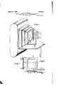
- Fig.1 is an isometric perspective viewof a camera with the sliader contained in 'it;
- Fig. 2 is a section of the shader on line 22 of Fig. 4.
- Fig. 3 is a section of the shader on lines 33 of Fig. 4.
- Fig; 4 is an elevation of the shader
- Fig. .5 is an elevation of an obstruction screen after exposure and the appearance of the photographically formed obstructions.
- an obstruction screen with a covering protecting it from h ght when outside the shader.
- Fig. 8 an elevation of the upper part of the shader withthe obstruction screen inserted in it.
- Fig- 9 IS a view of arr-obstruction screen that has been manipulated after exposure;
- Fig. 10-i-s a view of acamera having two shaders.
- Fig-'6 is a sideelevation of'an obstruction screen-with a light proof backing.
- Fig- 7 1s av1ew of Fig; 11is a view lot a mechanically produced obstruction screen: that can be used to modify the photograph-- ically produced obstruction screen.
- 12 is aview of obstructions photographically produced onan obstructionscreen which have been modified by the use of the mechanically produced obstructions shown in Fig.1 11-.
- Fig. 14- is a side; elevationof the upper part of a shader with the obstruction screen inserted therein.
- the'base' of a solid will be the area on the plate, the other the undiaphragmed area of the lens. If the solid having its basethe area on the late is cut by a plane passed perpendicularly to the axis of the lens, the figure formed on this plane by the intersection of it with the surfaces of this area, will be a space through which no light passes from the lens to the plate that does not reach this area on the plate.
- the shaders obstructions must cover part of the area of the figure thus formed, or must obstruct the passage of some of the light rays through it.
- the shader, 3, contains the obstruction screen, 5.
- the obstruction screen is made sensitive, photographically, and, when it has been exposed and developed, it presents a locally shaded appearance, its most shaded areas being where the light that has passed through the lens, 1, of the camera, has been received most intensely.
- the density of these obstructions is effected by the fact that light reflected from areas that are distinct from each other in the sub ject and in the image, frequently, on account of the converging of the rays passing through the lens, will reach the same area of the obstruction screen.
- An obstructions area can be considered as a composite of the figures formed by the intersection of the plane containing the surface of the screen with the aforementioned geometrical solids having their bases at the lens and at the various areas on the plate, 161, and its density will vary accordingly.
- the shadtings will. be suiliciently definite to enable the operator to tell what areas of the image plate, 161, will receive the light passing through the various areas on the obstriiictionscreen.
- the obstructions on the obstruction screen that are-directly photographically produced are often suiiicient without other manipulation of the obstruction screen.
- a blue print mixture coated on a celluloid film may form the screen.
- the screen, 5, may have a backing impervious to light 6, very convenieutly of black paper
- the shader, 3, may have supports, 22, 22, 23, 23, to hold the screen, 5, and the closer, a.
- the screens, 5, may be protected by a light proof covering, 7, that is pushed back as it is inserted in the shader, 3.
- Fig. 9 is a manipulated screen.
- the screen material may be cut away in an'area, 12, of the darkly shaded area, 13, and the holes, 15, 15, 15, 15, made in the screen materialin the very darkly shadedp'art, 14. Cutting holes in the screen material through the photographically produced obstructions will sharpen and brighten the picture'at the areas affected by these portions of the screen, and emphasize these portions of the picture.
- Figs. 11 and 12 show an auxiliary screen, 85, and the developed photographically produced screen obtained by using them in the double shader camera shown in Fig. 10.
- the obstruction, 30, (carried by the arm, 31) will shade an area as 12 (see Fig. 12) from receiving light from the lens lessening the density of the photographically produced obstruction on it.
- the sharp ness or diffusion of this decrease in density will depend on the relative distance of the obstruction, 30, from the lens and the obstruction screen.
- the area of lessened density, 30, may be, and it ordinarily within a dense area, 31.
- Using an auxiliary screen can replace cutting the obstruction screen often. Obviously many obstruction shapes can be placed in the obstruction screens.
- Coloring the screen locally with a transparent varnish will enable the screen to produce upon the image plate locally an effect analogous to that produced by the ordinary color screen. It will not, of course, produce any coloring of the image plate or the picture, but will accentuate or lessen merely the densening ef fect of a particular color of a particular area of the object on a corri-isponding area of the image plate.
- the sensitized obstruction screen is placed in the shader and placed in the camera as shown in Fig. 1 in the bellows, 2, at the distance re quired between the lens and the image plate.
- the shutter is then opened, and the sensitized surface of the obstruction screen acted upon by the light.
- the area of the screen being usually only one third of the area of the plate, the intensity of the light falling on any area of it will be usually thrice that which would fall on a like area of the plate.
- the time of exposure of the screen will therefore be l1'll1Cl1.Sl1OItI' than on the plate for the same sensitized material.
- the screen is then removed from the camera and developed. It is then manipulated if desired and holes cut in the portions of greatest density or additional obstructions placed upon the screen, parts of the screen colored with various transparent colors such as will conduct to the effectiveness of the screen. The diminution of the detail without materially diminishing the lighting can be secured by a coating of varnish that is slightly roughened.
- the manipulation of the screen can also be carried out within the camera.
- the screen can be itself screened by an obstruction placed between it and the lens while the former is exposed. This obstruction will lighten the density of the obstruction screen at the portions it affects. This has been described above. This obstruction screen can be spaced from the screen as far as is advantageous, the nearer the lens it is the more diffused its effect upon the screen.
- Additional manually applied obstructions as 69 can be placed on the screen, 5, see Figs. 5 and 9, which can be positioned in view of the indications on the developed screen.
- a shader for cameras having an obstruction screen composed of transparent material with obstructions photographically formed thereon.
- a shader for cameras having an obstruction screen composed of transparent material with obstructions photographically formed thereon and auxiliary obstructions formed by hand.
- a shader for cameras having an obstruction screen composed of transparent material, having thereon obstructions photographically formed and with diminutions of density in the more dense portions of these obstructions.
- a shader for cameras having an obstruction screen composed of a transparent material having thereon obstructions photographically formed and colored obstructions set with reference to the photographically formed obstructions.
- the art of regulating locally the shading of a photograph which consists in forming photographically an obstruction screen by exposing a sensitized screen between the lens and the image plate of a camera and ren'ioving and developing the same, replacing the screen in position and. taking the photographic negative through the obstruction screen.
- the art 01 regulating locally the shad ing of a photograph which consists in cansing the light passing through the lens from the object to the sensitized medium, to pass also through an obstruction screen with photographically produced obstructions.
Landscapes
- Physics & Mathematics (AREA)
- General Physics & Mathematics (AREA)
- Cameras In General (AREA)
Description
M. W. COLLET March '27, 1928.
' SHADER FOR CAMERAS AND IN THE ART OF REGULATING LOCALLY THE SHADING OF A PHOTOGRAPH Flled Feb 4 1919 2 Sheets-Sheet 1 March 27, 1928, 1,663,996
M. W. COLLET SHADER FOR CAMERAS AND IN THE ART OF REGULATING LOCALLY THE SHADING OF A PHOTQGRAPH Filed Feb. 4, 1919 4.2 Sheets-Sheet 2 Patented Mar. 27, 192
UNITED STATES manx'w. comm, or'rmnmnma, mmnvmm SHADER FOR cAmERAs-Ann'm err-mam or anamA-rmsLocAnLY arm snannm or A rrm'roomnm- Application filed February 4, 1919. Serialdio. 275 080 In shaders for cameras and in the art of regulating locally the shading of a photograph, of whichthe following is a specification, the device and. the practice of the 5 art depend upon the principle that reduction of the quantity of light falling on areas of a sensitive plate or sensitive film canbe effected by the placing ofobstructions between the plate. or the film and the lens that willcnt off a portion of the light that passes through the lens and would, if these obstructions were .not so'placed, impinge upon points in areas to beshadedr The general principles governing the positionconformation and arrangement. and some of the purposes of so doing are set forthin my Patent No. 1,254,579, dated Jan. 22nd, 1918.
My present device and process enables these ObSlllllOlllOIlS to be positioned more" readily and certainly; the obstructions are produced photographically, or a photographic indication of their appropriate positions, shapes and the depth of shading is produced so that appropriate obstructions may be laid to effect the desired shading of Fig.1 is an isometric perspective viewof a camera with the sliader contained in 'it;
the bellows being broken away to show the shader clearly. Fig. 2 is a section of the shader on line 22 of Fig. 4. Fig. 3 is a section of the shader on lines 33 of Fig. 4.
Fig; 4 is an elevation of the shader; Fig. .5 is an elevation of an obstruction screen after exposure and the appearance of the photographically formed obstructions.
an obstruction screen with a covering; protecting it from h ght when outside the shader.
Fig. 8 an elevation of the upper part of the shader withthe obstruction screen inserted in it. Fig- 9 IS a view of arr-obstruction screen that has been manipulated after exposure; Fig. 10-i-s a view of acamera having two shaders.
ing of such obstructions, their construction,
Fig-'6 is a sideelevation of'an obstruction screen-with a light proof backing. Fig- 7 1s av1ew of Fig; 11is a view lot a mechanically produced obstruction screen: that can be used to modify the photograph-- ically produced obstruction screen. 12 is aview of obstructions photographically produced onan obstructionscreen which have been modified by the use of the mechanically produced obstructions shown in Fig.1 11-. F igc. .13; shows an obstruction screen wherethe light diminishing obstructions are colored varnishes Fig. 14- is a side; elevationof the upper part of a shader with the obstruction screen inserted therein.
I 1,663,996.. PATENT OFF An obstructions-elfect is-more localized -andintensified the nearer it is positioned to thesensitive plate or film, andis difl'used in proportion as it is moved nearer the lens. Placed directly in front of. the plate or film it will, if dense enough, stencilthe image. Placed directly at the'lens, it will diminish the lighting generally over the plate with out materially, or-even sensibly disturbing the ratio of the lighting. of one area of the image to another area thereof from the ratio existing before the obstruction screen was inserted. The screen or screens are positioned, I believe,lmost usefully when placed tron 1 50% to 80% of the distance from the lens, 1. to theplate, 151 or film, 161.
All light reachingaany particular area of theisensitive plate (forshortnessin this-dis cussion where or film= is to be understood) will lie ina geometrical'solid havingas one'of the boundingsurfaces the areaofthe lens throu h which pasmge of light is permitted by t ediaphragnn generally; called the undiaphragmed openingof the lens, another'the' figure of the'particular area of the plate,
plate is expressly mentioned,
and practically, but not exactly, a surface -undiaphragmed-iopening of the lens, and
the other a line bounding-the area on' the plate under consideration; the two lines not crossing between thelens and the plate. It a plane is passed perpendicular to the axis of the lens, between the lens and plate, its intersection with the surfaces of this solid will be cut in: afigurethat' will contain all rays'of light passingthroughthe lens. and:treacl1ing: this area on the plate. If the two right lines in the above mentionedplane whose axis of revolution coincides with-the axis of the lens cross,;then
two geometrical' solids will-be produeed having. .coincident apices, the'base' of a solid will be the area on the plate, the other the undiaphragmed area of the lens. If the solid having its basethe area on the late is cut by a plane passed perpendicularly to the axis of the lens, the figure formed on this plane by the intersection of it with the surfaces of this area, will be a space through which no light passes from the lens to the plate that does not reach this area on the plate.
The shaders obstructions must cover part of the area of the figure thus formed, or must obstruct the passage of some of the light rays through it.
I have devised means whereby this can be acconrplished by direct photographic action, and the necessary obstructions can be prodr ed without need of inspecting the interior of the camera. The shader, 3, contains the obstruction screen, 5. The obstruction screen is made sensitive, photographically, and, when it has been exposed and developed, it presents a locally shaded appearance, its most shaded areas being where the light that has passed through the lens, 1, of the camera, has been received most intensely. The density of these obstructions is effected by the fact that light reflected from areas that are distinct from each other in the sub ject and in the image, frequently, on account of the converging of the rays passing through the lens, will reach the same area of the obstruction screen. An obstructions area can be considered as a composite of the figures formed by the intersection of the plane containing the surface of the screen with the aforementioned geometrical solids having their bases at the lens and at the various areas on the plate, 161, and its density will vary accordingly. The shadtings will. be suiliciently definite to enable the operator to tell what areas of the image plate, 161, will receive the light passing through the various areas on the obstriiictionscreen. The obstructions on the obstruction screen that are-directly photographically produced are often suiiicient without other manipulation of the obstruction screen.
No particular way of sensitizing the obstruction screen, 5, is necessary. A blue print mixture coated on a celluloid film may form the screen. The screen, 5, may have a backing impervious to light 6, very convenieutly of black paper The shader, 3, may have supports, 22, 22, 23, 23, to hold the screen, 5, and the closer, a. The screens, 5, may be protected by a light proof covering, 7, that is pushed back as it is inserted in the shader, 3.
its an example of a developed obstruction screen: 5 shows a higl'ily shaded portion, 1, detached shaded area, 9, and a very densely shaded portion, 69, and a much less densely obstructed area or entirely unob structed area, 18. Fig. 9 is a manipulated screen. The screen material may be cut away in an'area, 12, of the darkly shaded area, 13, and the holes, 15, 15, 15, 15, made in the screen materialin the very darkly shadedp'art, 14. Cutting holes in the screen material through the photographically produced obstructions will sharpen and brighten the picture'at the areas affected by these portions of the screen, and emphasize these portions of the picture. Figs. 11 and 12 show an auxiliary screen, 85, and the developed photographically produced screen obtained by using them in the double shader camera shown in Fig. 10. The screen, 85,
is placed in the front, 231, and the sensitized 7 but undeveloped screen, 96, is placed in the holder, 3. The obstruction, 30, (carried by the arm, 31) will shade an area as 12 (see Fig. 12) from receiving light from the lens lessening the density of the photographically produced obstruction on it. The sharp ness or diffusion of this decrease in density will depend on the relative distance of the obstruction, 30, from the lens and the obstruction screen. The area of lessened density, 30, may be, and it ordinarily within a dense area, 31. Using an auxiliary screen can replace cutting the obstruction screen often. Obviously many obstruction shapes can be placed in the obstruction screens.
Using the screen originally inserted in the shader, 3, as a guide for forming an obstruction screen with transparent colors on various areas, will often produce nirticularly artistic results, the varying densities of areas indicating the areas to which the colors should be applied. The colors iniilicated in Fig. 13, are blue on thearea, 48, yellow on the area, 49, and red on the area, 50, the area, 47, being left untinted. A. transparent varnish tinted to the desired color is used in practice, and the screen produced photographically can either be tinted on it or a transparent screen used as the obstruction screen, the screen produced 'photographically being used only as a pattern. Coloring the screen locally with a transparent varnish will enable the screen to produce upon the image plate locally an effect analogous to that produced by the ordinary color screen. It will not, of course, produce any coloring of the image plate or the picture, but will accentuate or lessen merely the densening ef fect of a particular color of a particular area of the object on a corri-isponding area of the image plate.
The process of carrying out my invented art as I consider besthas been indicated in part in describing the device itself, and I will now describe only the portions of the process not fully set forth above. The sensitized obstruction screen is placed in the shader and placed in the camera as shown in Fig. 1 in the bellows, 2, at the distance re quired between the lens and the image plate. The shutter is then opened, and the sensitized surface of the obstruction screen acted upon by the light. The area of the screen being usually only one third of the area of the plate, the intensity of the light falling on any area of it will be usually thrice that which would fall on a like area of the plate. The time of exposure of the screen will therefore be l1'll1Cl1.Sl1OItI' than on the plate for the same sensitized material. The screen is then removed from the camera and developed. It is then manipulated if desired and holes cut in the portions of greatest density or additional obstructions placed upon the screen, parts of the screen colored with various transparent colors such as will conduce to the effectiveness of the screen. The diminution of the detail without materially diminishing the lighting can be secured by a coating of varnish that is slightly roughened. The manipulation of the screen can also be carried out within the camera. The screen can be itself screened by an obstruction placed between it and the lens while the former is exposed. This obstruction will lighten the density of the obstruction screen at the portions it affects. This has been described above. This obstruction screen can be spaced from the screen as far as is advantageous, the nearer the lens it is the more diffused its effect upon the screen.
\Vhile this is being done, the image plate is protected from the light passing through the lens and acting upon the screen. During the exposure of the screen, this light is stopped from reaching the image plate by the body of the shader, by the backing of the screen, or the screen itself. The shutter can he closed before the screen is removed.
The screen after it has been developed, and, if desired, manipulated, is replaced in the shader, and the exposure given to form the image on the sensitive plate. This exposure will have to be somewhat longer than if no screen were used. If the screen exposed is used as a pattern only, then the one built up from it inserted in its place in the shader, the process being otherwise the same.
Additional manually applied obstructions as 69 can be placed on the screen, 5, see Figs. 5 and 9, which can be positioned in view of the indications on the developed screen.
I claim 1. A shader for cameras, having an obstruction screen composed of transparent material with obstructions photographically formed thereon.
2. A shader for cameras, having an obstruction screen composed of transparent material with obstructions photographically formed thereon and auxiliary obstructions formed by hand.
3. A shader for cameras, having an obstruction screen composed of transparent material, having thereon obstructions photographically formed and with diminutions of density in the more dense portions of these obstructions.
4. A shader for cameras, having an obstruction screen composed of a transparent material having thereon obstructions photographically formed and colored obstructions set with reference to the photographically formed obstructions.
5. The art of regulating locally the shading of a photograph, which consists in forming photographically an obstruction screen by exposing a sensitized screen between the lens and the image plate of a camera and ren'ioving and developing the same, replacing the screen in position and. taking the photographic negative through the obstruction screen.
6. The art of regulating locally the shading of a photograph, which consists in forming an obstruction screen by exposing a sensitized screen in the camera between the lens and the image plate and removing and developing the same, treating the developed screen to change manually its shading efiect, replacing the screen in position and taking the photographic negative through the screen.
7. The process of regulating locally the shading of a photograph, which consists in producing a photographic negative screen of the object, and then photographing the object upon a sensitive medium while intercepting some of the rays of light from said ohject by means of said negative screen.
8. The art 01 regulating locally the shad ing of a photograph, which consists in cansing the light passing through the lens from the object to the sensitized medium, to pass also through an obstruction screen with photographically produced obstructions.
9. The art of regulating locally the shading of a photograph which consists in cansing the light passing through the lens from the object to the sensitized medium, to pass also through an obstruction screen with, photographically produced obstructions, said obstruction screen being placed between the lens and the sensitized medium and spaced from each of them.
In Witness whereof I have hereunto set my signature.
MARK W. COLLET.
Priority Applications (1)
| Application Number | Priority Date | Filing Date | Title |
|---|---|---|---|
| US275020A US1663996A (en) | 1919-02-04 | 1919-02-04 | Shader for cameras and in the art of regulating locally the shading of a photograph |
Applications Claiming Priority (1)
| Application Number | Priority Date | Filing Date | Title |
|---|---|---|---|
| US275020A US1663996A (en) | 1919-02-04 | 1919-02-04 | Shader for cameras and in the art of regulating locally the shading of a photograph |
Publications (1)
| Publication Number | Publication Date |
|---|---|
| US1663996A true US1663996A (en) | 1928-03-27 |
Family
ID=23050575
Family Applications (1)
| Application Number | Title | Priority Date | Filing Date |
|---|---|---|---|
| US275020A Expired - Lifetime US1663996A (en) | 1919-02-04 | 1919-02-04 | Shader for cameras and in the art of regulating locally the shading of a photograph |
Country Status (1)
| Country | Link |
|---|---|
| US (1) | US1663996A (en) |
Cited By (3)
| Publication number | Priority date | Publication date | Assignee | Title |
|---|---|---|---|---|
| US3212891A (en) * | 1963-01-21 | 1965-10-19 | Western Electric Co | Method of correcting a half-tone print for reproduction |
| US3263079A (en) * | 1962-11-26 | 1966-07-26 | Block Engineering | Method for forming an image of an invisible radiation pattern and apparatus for copying the image |
| US3704687A (en) * | 1970-12-21 | 1972-12-05 | Ryotaro Nohmura | Fish farming nest |
-
1919
- 1919-02-04 US US275020A patent/US1663996A/en not_active Expired - Lifetime
Cited By (3)
| Publication number | Priority date | Publication date | Assignee | Title |
|---|---|---|---|---|
| US3263079A (en) * | 1962-11-26 | 1966-07-26 | Block Engineering | Method for forming an image of an invisible radiation pattern and apparatus for copying the image |
| US3212891A (en) * | 1963-01-21 | 1965-10-19 | Western Electric Co | Method of correcting a half-tone print for reproduction |
| US3704687A (en) * | 1970-12-21 | 1972-12-05 | Ryotaro Nohmura | Fish farming nest |
Similar Documents
| Publication | Publication Date | Title |
|---|---|---|
| US2455849A (en) | Photographic unsharp masking method | |
| US2352914A (en) | Photographic printing | |
| US1663996A (en) | Shader for cameras and in the art of regulating locally the shading of a photograph | |
| US3469914A (en) | Enlarger head for use with variable contrast paper | |
| US3096176A (en) | Photographic printing method | |
| US1795050A (en) | Apparatus for producing margined photographs | |
| US1883884A (en) | Photographic sensitometer | |
| US3449045A (en) | Additive lamphouse | |
| US1804727A (en) | Photography | |
| US3164056A (en) | Photographic copying machine | |
| US4351608A (en) | Filter head | |
| US1960373A (en) | Art of cinematography | |
| US2865744A (en) | Fluorescence in photographic emulsions and duplicating process using such fluorescence | |
| US2206054A (en) | Method of forming color screens | |
| Mees | The fundamentals of photography | |
| US2912325A (en) | Light-sensitive film prescreened by herschel exposure | |
| US2244304A (en) | Photographic process | |
| US774549A (en) | Photographic process for the reproduction of plastic objects. | |
| US1127763A (en) | Photographic appliance. | |
| US1351430A (en) | lttboshey | |
| US2219703A (en) | Photographic test strip | |
| US2987397A (en) | Method of prescreening of film | |
| GB1178822A (en) | Flash Installation on Process Cameras and Enlargers | |
| US2478444A (en) | Manufacture of photographic contact screens | |
| Lawrence | The Scientific Photographer |