US1663995A - Condenser - Google Patents
Condenser Download PDFInfo
- Publication number
- US1663995A US1663995A US706178A US70617824A US1663995A US 1663995 A US1663995 A US 1663995A US 706178 A US706178 A US 706178A US 70617824 A US70617824 A US 70617824A US 1663995 A US1663995 A US 1663995A
- Authority
- US
- United States
- Prior art keywords
- tank
- pipe
- coil
- hollow
- members
- Prior art date
- Legal status (The legal status is an assumption and is not a legal conclusion. Google has not performed a legal analysis and makes no representation as to the accuracy of the status listed.)
- Expired - Lifetime
Links
Images

Classifications
-
- F—MECHANICAL ENGINEERING; LIGHTING; HEATING; WEAPONS; BLASTING
- F25—REFRIGERATION OR COOLING; COMBINED HEATING AND REFRIGERATION SYSTEMS; HEAT PUMP SYSTEMS; MANUFACTURE OR STORAGE OF ICE; LIQUEFACTION SOLIDIFICATION OF GASES
- F25B—REFRIGERATION MACHINES, PLANTS OR SYSTEMS; COMBINED HEATING AND REFRIGERATION SYSTEMS; HEAT PUMP SYSTEMS
- F25B39/00—Evaporators; Condensers
- F25B39/04—Condensers
-
- F—MECHANICAL ENGINEERING; LIGHTING; HEATING; WEAPONS; BLASTING
- F25—REFRIGERATION OR COOLING; COMBINED HEATING AND REFRIGERATION SYSTEMS; HEAT PUMP SYSTEMS; MANUFACTURE OR STORAGE OF ICE; LIQUEFACTION SOLIDIFICATION OF GASES
- F25B—REFRIGERATION MACHINES, PLANTS OR SYSTEMS; COMBINED HEATING AND REFRIGERATION SYSTEMS; HEAT PUMP SYSTEMS
- F25B17/00—Sorption machines, plants or systems, operating intermittently, e.g. absorption or adsorption type
- F25B17/02—Sorption machines, plants or systems, operating intermittently, e.g. absorption or adsorption type the absorbent or adsorbent being a liquid, e.g. brine
Definitions
- This invention relates to ithe art of :refrigeration and lhas ifor zit-S iobje'ct 'theiprovision of a refrigerating apparatus'which entirely eliminates the use ofiice and hich 'emp'loys ammonium ihydroxide'fas its :active agent, means ibing iprotide'd ifor "producing the necessary liquefaction and :expansion.
- thermostatic closer tomatically by av thermostatic closer.- (and: similar thermostatic means beingiprovided in "the brine ttank whereby do make vthe entire- :inechanism automatic and continuous in aac
- a further-object is the iprovision of a (den ivice 03. this "nature -well :adapted for con-- struction on asmall scale -ior domestic user
- Another-object is the provision Ofnflll ap :paratus of this character including peculiar; zme'ans 'forssepaiiaitingvsteam ifrom the: ammo-. nia.
- the invention consists ..-in the :details of -.construction to the khereinafter more fiulLy described and claimed and tlllllS- trated in the accompanying drawings, in which: a
- a suitable check 'valve 16 is interposed in the zip'ipe 12 forthe purpose 'of prevcnting back ipressure:therethrough.
- I also provide' a separating device including a tank 24 Within Wll lCh aTG located hollow members25 connected by pipes 26' which .are staggered as shown so as to provide a vcircuitous passage.
- the numeral 10 designatesa brineetank; withinwhich is alocn'ted .an .GXPRIlSiOIlflOll 11-; ifrom the 'lowerend of which ileads' a pipe :12.
- the numeral 13 designates heating tank containing water and provided with an -out let :pipe :14 :having iajoint15 therein.
- the pipe 12 enters the tank 13 and extenolsathere-v diameter tubing c in-29 .jf ormedpof small I .Theffirst one of which acts as acondensen.
- .the serics of.holloyv -mcmbers 25 is connected witha' pipe 30 which leads, from the connection 15...
- drain tubes 81 connected with the piPe'ZBQ, 'bythe T-Fs and elbows 32 and .33Yrespectively. .A; .check valve 34 is interposeclbetweenthe pipe 30 and the fpipes 31 f for preventing back pressure and similar check valves are provided in all of the tubes 31.
- the separator is designed to separate the water from. the ammonia and does so very satisfactorily. However, in case there should by any chance be a small quantity of water getting past the separator, I have designed-the condenser so that this moisture may be condensed in the first few convolutions and drained back to the boiler.-
- an automatic pressure reducing valve 40 of any ordinary or preferred type which will automatically operate to permit only a certain pressure to pass therethrough.
- This valye is equipped with a thermostatic device 40 which will operate to closethe valve when the brine has reached a certain lowtemperature thereby preventing more liquid passing through.
- Two or more of the uppermost convolutions of the coil 29 are equipped with drain while theammonia'gaspasses on through tubes 41 which lead to admin pipe 42 which connects with one of the branches of the joint15. It is preferable that a check valve 43 be interposed in this pipe or'tube 42'to prevent back pressure.
- the ammonia gas passing on through the coil 29 is cooled by the water in the tank 27 and' collects in liquid form in the receiving coil 28. Any moisture passing over into the coil 29 with the ammonia will condense in the first few convolutions and drain through the tubes 41 into the pipe42 and back to the pipe 14 and tank 13. In this way it will be seen that only the pure ammonia accumulates within the receiving coil 28. This continues until the charge in the boiler 13 is exhausted and its temperature reaches 273 Fahrenheit at which point the thermostat 18 opens and breaks the circuit to the electric heater.
- a separator comprising a tank adapted to be filled with cooling liquid, a plurality of spaced parallel upright hollow members located within the tank in spaced relation to the walls thereof, an inlet pipe leading to the bottom of the first one of the plurality of hollow upright members, pipes connecting successive ones of said hollow upright members alternately at the upper and lower portions thereof, an outlet pipe leading from the top of the last'one of the plurality of hollow upright members, and a return pipe having check valved communication with all of the hollow upright members and connected with said inlet pipe.
Landscapes
- Engineering & Computer Science (AREA)
- Physics & Mathematics (AREA)
- Mechanical Engineering (AREA)
- Thermal Sciences (AREA)
- General Engineering & Computer Science (AREA)
- Sorption Type Refrigeration Machines (AREA)
Description
M h 27, 1928. I
arc I F. L. BRYANT CONDENSER Fi April 12. 1924 2 Sheets-Sheet 1 :{IEIHII ll wrruzss: ATTJORNEY March 27, 1928 WITNESS:
F. L. BRYANT commussa Filed April 12. 1924 2 Sheets-Sheet 2 INVENTOR ATTORNEY Patented Mar. 27, 1928.
messes roxmnsr "L. BRYANT, or
B'Inenmrrom NEW ORK.
connn'nsnn.
n iieanmi filed inna This invention relates to ithe art of :refrigeration and lhas ifor zit-S iobje'ct 'theiprovision of a refrigerating apparatus'which entirely eliminates the use ofiice and hich 'emp'loys ammonium ihydroxide'fas its :active agent, means ibing iprotide'd ifor "producing the necessary liquefaction and :expansion.
' The essential feature ilies 'in' the provision" of an :apparatus :of this charaetermtili-zing' :an alosorpti'on emethod for.rproilucing a con- ,ionc en =stant circulationrofttheiammoniaaelectrically operated sheating :means lbein-g controlled au- 1shoWingimy-system --and:appara=tus,-
tomatically by av thermostatic closer.- (and: similar thermostatic means beingiprovided in "the brine ttank whereby do make vthe entire- :inechanism automatic and continuous in aac A further-object is the iprovision of a (den ivice 03. this "nature -well :adapted for con-- struction on asmall scale -ior domestic user Another-object is the provision Ofnflll ap :paratus of this character including peculiar; zme'ans 'forssepaiiaitingvsteam ifrom the: ammo-. nia. this :unit zbeing interposed be the heating mcanszand:thecondenserp I 7 An additionalob'ect slS the provision 'mechanism :of ithis icharacter which will be simple and rinebtpensive-to manufactureseasy 'to install and ioperate, positive andcflicient tin service and a :general improvement tinithe "art. I t
- With the: above and other objects and {advantagcs in view the invention consists ..-in the :details of -.construction to the khereinafter more fiulLy described and claimed and tlllllS- trated in the accompanying drawings, in which: a
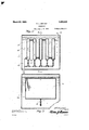
Figure 1 isarsomexvhat diagrammatic view,
Figure '2 :is .a detail "section'rthrou gh atlie' separator :and *1 =,;these circuit vclosers ofa' galong, near the bottom. The portion ofthe :pIpe tS.;llnd8ISld8 While'its end is plugged. A suitable check 'valve 16 "is interposed in the zip'ipe 12 forthe purpose 'of prevcnting back ipressure:therethrough. Y
' VVi hin the tank '13 is anelectri'chcater17 th current from any suitable source.
d olf-thisitankis thermostatic circuit ircloser 18 from which 'lead wires 19 and 20, lthe former 01: I which is connected with one "terminal ofthe heatingcoil 17. and the lattenofqvhich-is connected with oiie poleiof ;w-hatever..-source of; current is used. 1
-;In the 'tank 10 'is aythermostatic circuit closer 21 to which are-tconnected .Wires'22- sand -23, the .former. iof' which is connected "-Wltl1"t'h-8- other, terminal 'of the source of current iandjthe. -latter of whichaisconnected .wvith theother terminal ..of theiheating coil 17. Th e anrangement-nndia djustlnent :of :is. such that when the temperature of the waterlwithin the tank 113 ,dropswbelow laqcert'ain .degree, the circuit ,closerfi18 vwill.operate .to elose .the circuit through the: heater 1,7, and is" furthermore suchithat whenthcutemperaturc ofthebrine inthe tank 10 reaches a certain lovv tcmpera ,ture,
thecircuit tothe electri cheater Both thermostats thusiact in unisonfand each is a check Onzthfifltht. f i
I also provide' a separating device including a tank 24 Within Wll lCh aTG located hollow members25 connected by pipes 26' which .are staggered as shown so as to provide a vcircuitous passage.
Beyond the separator ,is .theflcondensier which includes a tank 27 \vi thin the lower ,portion of, which is a. coil .28.of tubingjho f relatively large diameter of ranyiordinary. ior preferred type suppliid v 12 *within .the tank 131is perforated-on the lthermostatBl, will opembreaking Figurefi is a-crossiseotion-onfthe.linei3 3 l3 llg {la-receiver. d e' ving fr m of Figurefi. v
Referring :more particularly/{to the draw-- ings the numeral 10 designatesa brineetank; withinwhich is alocn'ted .an .GXPRIlSiOIlflOll 11-; ifrom the 'lowerend of which ileads' a pipe :12. The numeral 13 designates heating tank containing water and provided with an -out let :pipe :14 :having iajoint15 therein. The pipe 12 enters the tank 13 and extenolsathere-v diameter tubing c in-29 .jf ormedpof small I .Theffirst one of which acts as acondensen.
.the serics of.holloyv -mcmbers 25 is connected witha' pipe 30 which leads, from the connection 15... At the bottoms of the hollow memloers 25121113 drain tubes 81 connected with the piPe'ZBQ, 'bythe T-Fs and elbows 32 and .33Yrespectively. .A; .check valve 34 is interposeclbetweenthe pipe 30 and the fpipes 31 f for preventing back pressure and similar check valves are provided in all of the tubes 31. The separator is designed to separate the water from. the ammonia and does so very satisfactorily. However, in case there should by any chance be a small quantity of water getting past the separator, I have designed-the condenser so that this moisture may be condensed in the first few convolutions and drained back to the boiler.-
leads into thebrine tank 10 and which con-' nects with the expansion coil 11 therein. At
the juncture of the pipe39 with the expansion coil is an automatic pressure reducing valve 40 of any ordinary or preferred type which will automatically operate to permit only a certain pressure to pass therethrough. This valye is equipped with a thermostatic device 40 which will operate to closethe valve when the brine has reached a certain lowtemperature thereby preventing more liquid passing through.
Two or more of the uppermost convolutions of the coil 29 are equipped with drain while theammonia'gaspasses on through tubes 41 which lead to admin pipe 42 which connects with one of the branches of the joint15. It is preferable that a check valve 43 be interposed in this pipe or'tube 42'to prevent back pressure. I
In the operation, assumingthat the parts are constructed and arranged as described,
and thatthe brine tank'is full and that the .tank 13 is filled with ammonium hydroxide 4 and the systempurgedfof air, the thermostats are both in closed position and the electric circuit to the heater '17 is complete. When the heater has heated the ammonium hydroxide in the tank 13, a mixture of am monia and steam will pass out through the pipe 14 and pipe 30 into the hollow mem-' bers 25 of the separating device. The tank 24 of the separating device is full of water and this water will cool and condense the steam passing through the members 25 the pipe36 and into the coil 29. The water condensed, in the members 25 passes down through the tubes 31 and check valves '35 and through the check valve 34 into the pipe 30 thence back into the tank 13. The ammonia gas passing on through the coil 29 is cooled by the water in the tank 27 and' collects in liquid form in the receiving coil 28. Any moisture passing over into the coil 29 with the ammonia will condense in the first few convolutions and drain through the tubes 41 into the pipe42 and back to the pipe 14 and tank 13. In this way it will be seen that only the pure ammonia accumulates within the receiving coil 28. This continues until the charge in the boiler 13 is exhausted and its temperature reaches 273 Fahrenheit at which point the thermostat 18 opens and breaks the circuit to the electric heater. 7 The boiler now begins to cool and to reabsorb ammonia, but owing to the various checking valves interposed throughout the system, ammonia can be drawn into this tank 13 only by way of the expansion coil 11, the liquid being drawn by suction from the receiving coil 28 through the pipe 39 and valve40, through the-coil 11,,pipe 12 check valve 16 and thence into the tank 13. The valve 40 operates tocontrol' the pressure. 'The expansion: of the ammonia" passing through the coil'll causes itto absorb the'heat from the'brine, thus producing the desired refrigerating efiect. 1 When the boiler has become cooledxand hasreab sorbed. all the ammonia, the thermostats 18' 'and'21'again close foi' energiz ing the electric heater, thus completing the cycle of -operation. V
The extension of the pipe 12 into thetank 13 and'the' perforations constitute an im-l portant feature 'as all the gas that returns from the expansion coils must pass directly throughjthe'v water, thus preventing, any air in the" system from cushioning down on the water and slowing up reabsorption.
i From the foregoing description and a study" of the drawingsf it will be apparent that'I havethus provideda very simple and novel method of and apparatu's for producing refrigeration without ice','th ere being nonecessity for the employme'nt' of anypumps or other positive circulating" device, the cir- While I have shown and described the preferred embodimentof my invention it" is of rightto'make such changes in the-form, construction and arrangement of parts ,as will not depart from the spirit oftheinvention orthe scope of the subj'oined-claims.
ity of hollow'm'embers located within the tank, an inlet pipe leading to the bottom of the first one'of the plurality of hollow members. pipes connecting the successive ones 'of said hollow (members; alternately at the top and bottom thereof, an outlet pipe leading from the top of the last one of the plurality of hollow members,a return pipe leading to said inlet pipe and connected with the bottoms of the'respective hollow members,
and check valves tions.
2. In an apparatus of the character deinterposed in said connecculation being effected purely by absorption.
course to be understood that I reserve 'the scribed, a separator comprising a tank adapted to be filled with cooling liquid, a plurality of spaced parallel upright hollow members located within the tank in spaced relation to the walls thereof, an inlet pipe leading to the bottom of the first one of the plurality of hollow upright members, pipes connecting successive ones of said hollow upright members alternately at the upper and lower portions thereof, an outlet pipe leading from the top of the last'one of the plurality of hollow upright members, and a return pipe having check valved communication with all of the hollow upright members and connected with said inlet pipe. y
a In testimony whereof I alfix my signature.
' FORREST L. BRYANT.
Priority Applications (1)
| Application Number | Priority Date | Filing Date | Title |
|---|---|---|---|
| US706178A US1663995A (en) | 1924-04-12 | 1924-04-12 | Condenser |
Applications Claiming Priority (1)
| Application Number | Priority Date | Filing Date | Title |
|---|---|---|---|
| US706178A US1663995A (en) | 1924-04-12 | 1924-04-12 | Condenser |
Publications (1)
| Publication Number | Publication Date |
|---|---|
| US1663995A true US1663995A (en) | 1928-03-27 |
Family
ID=24836519
Family Applications (1)
| Application Number | Title | Priority Date | Filing Date |
|---|---|---|---|
| US706178A Expired - Lifetime US1663995A (en) | 1924-04-12 | 1924-04-12 | Condenser |
Country Status (1)
| Country | Link |
|---|---|
| US (1) | US1663995A (en) |
-
1924
- 1924-04-12 US US706178A patent/US1663995A/en not_active Expired - Lifetime
Similar Documents
| Publication | Publication Date | Title |
|---|---|---|
| US2287441A (en) | Absorption refrigeration system | |
| US1663995A (en) | Condenser | |
| US2283213A (en) | Refrigerating system | |
| US2337439A (en) | Refrigeration | |
| US2374521A (en) | Refrigeration | |
| US2021994A (en) | Refrigerating apparatus | |
| US2557573A (en) | Air conditioning | |
| US2071026A (en) | Condenser for air conditioning systems | |
| US2307422A (en) | Cooling system for buildings | |
| US1385827A (en) | Condenser | |
| US2510730A (en) | Low-pressure absorption refrigerating system | |
| US482694A (en) | Thirds to william ii | |
| US1717173A (en) | Refrigerating apparatus | |
| US1134518A (en) | Condenser. | |
| US2313707A (en) | Absorption refrigerator | |
| US2465873A (en) | Refrigerating coil | |
| US2404511A (en) | Refrigerating method and apparatus | |
| US1451190A (en) | Gas condenser | |
| US2689466A (en) | Absorption refrigeration unit with a centrifugal separator | |
| US489897A (en) | fuller | |
| US1829716A (en) | Refrigerator | |
| US1524297A (en) | Apparatus for refrigeration | |
| US1200742A (en) | Refrigerating apparatus. | |
| US1993380A (en) | Absorption refrigerating apparatus | |
| US2079419A (en) | Refrigeration |