US1663993A - Friction shock-absorbing mechanism - Google Patents
Friction shock-absorbing mechanism Download PDFInfo
- Publication number
- US1663993A US1663993A US727109A US72710924A US1663993A US 1663993 A US1663993 A US 1663993A US 727109 A US727109 A US 727109A US 72710924 A US72710924 A US 72710924A US 1663993 A US1663993 A US 1663993A
- Authority
- US
- United States
- Prior art keywords
- friction
- plates
- wedge
- follower
- followers
- Prior art date
- Legal status (The legal status is an assumption and is not a legal conclusion. Google has not performed a legal analysis and makes no representation as to the accuracy of the status listed.)
- Expired - Lifetime
Links
- 230000007246 mechanism Effects 0.000 title description 32
- 230000000875 corresponding effect Effects 0.000 description 22
- 230000035939 shock Effects 0.000 description 16
- 230000009471 action Effects 0.000 description 4
- 230000006835 compression Effects 0.000 description 4
- 238000007906 compression Methods 0.000 description 4
- 238000010276 construction Methods 0.000 description 3
- 229920000136 polysorbate Polymers 0.000 description 2
- 230000007480 spreading Effects 0.000 description 2
- RTZKZFJDLAIYFH-UHFFFAOYSA-N Diethyl ether Chemical compound CCOCC RTZKZFJDLAIYFH-UHFFFAOYSA-N 0.000 description 1
- 230000003190 augmentative effect Effects 0.000 description 1
- 230000000694 effects Effects 0.000 description 1
- 230000004048 modification Effects 0.000 description 1
- 238000012986 modification Methods 0.000 description 1
- 230000009467 reduction Effects 0.000 description 1
- 238000006722 reduction reaction Methods 0.000 description 1
- 230000003578 releasing effect Effects 0.000 description 1
- 239000007787 solid Substances 0.000 description 1
Images

Classifications
-
- B—PERFORMING OPERATIONS; TRANSPORTING
- B61—RAILWAYS
- B61G—COUPLINGS; DRAUGHT AND BUFFING APPLIANCES
- B61G9/00—Draw-gear
- B61G9/04—Draw-gear combined with buffing appliances
- B61G9/10—Draw-gear combined with buffing appliances with separate mechanical friction shock-absorbers
Definitions
- This invention relates to iinpi ovenients'in friction shock absorbing mechanisms.
- One object of the invention is to provide a high capacity shock "absorbing mechanism, of the intercalated plate type, especially adapted'for railway draft riggings, havinginitial spring action during which relatively v parts of'the shock absorbing'lnechanism are supported by a'detachable saddle plate 15.
- Another object of the invention is to pro-' yide'a mechanism of 'the character indicated, including friction elements and spring-"resistance means," wherein the spring resistance is always available to absorb the shocks after each compression of the mechanism.
- a more specific object of the invention' is to provide ashock absorbing niechanisni of the double ended type, including tandem arranged spring resistance elements, directcooperating with. the main followers,and a'friction' system interposed between the tandem springs and cooperating therewith, thefrition system being directly actuatedby relative movement of the main followers.
- F gures Q'and 3 are transverse, vertical, sectional yiews of the.
- Figure 4 is a longitudinal, 1
- eachcasing is provided'with a pair of inwardly projecting hollow, spaced, I
- bosses: 2 1 ffor ,a purpose hereinafter described.
- the friction shell- B whichis also of hollow box-like form, is provided with' longitudinally disposed, spaced top and bottom' walls 22 22 and spaced, longitudinally disposed side walls '23''23; the shell being open at its opposite ends. Midwaybetween the endsofthe shell, each sidewall isinwardly offset indicated at 24-, the inner surface of the offset portionpresenting a relatively short; longitudinally disposed, friction surface 25. adapted to cooperatewith the outerni'o'st group of plate of thencorresponding pla 'E. The opposite ends of the friction sliel'l are ad'apted to telescopically receive; the
- red ucedfportions 19 of the front and rear follower casings respectiyely and the shell" is ofsuch alengththat the opposite ends thereof areequally spa-ced froin the shoulders" 20 of the fr ont and' rear'casin fzs Aether v spacing! being such that the shoulders will; abutthe oppositeends ,Qfthe ⁇ shell when the mechanism is fully compressed, thereby limiting the relative movement of the front and rear follower casings and transmitting the force directly through said follower casings and shell to one of the pairs of stop lugs.
- the front and rear wedge members C are of like construction, each comprising a main block-like portion 26 and top and bottom,.
- each of the wedge members is provided with a pairof inwardly converging wedge faces 2828 at the inner end thereof, the wedge faces 28 being disposed on opposite sides of the central axis of the mechanism, and each-adapted to cooperate with one of the friction wedge shoes D.
- the body portion of each wedgemeniber is also provided with afiat end face 29 adapted to form an abutment for the corresponding spring follower plate F.
- the top and bottom flange sections 27 of'each wedge member embrace the corresponding spring followerand have their extreme outer ends slightly spaced from the inner ends of the corresponding top and bottom walls of the adjacent follower casing A, as clearly shown in Figure 1.
- the space between each wedge member C and corresponding follower casing A permits of a predetermined amount of initial compression ofthe mechanism, after which the inner end of the follower casing A positively engages with the corresponding wedge C to actuate the latter.
- the friction wedge shoes D are number, arranged in pairs, cooperating with the corresponding wedge members C.
- the shoes D are all of like construction, each shoe comprising a vertically disposed, heavy plate-like section 30 and horizontally dis: posed top andbottom flanges Ell-31
- the top and bottom flanges 31 of each shoe D are cut away to present wedge faces 128 correspondingly inclined to, and adapted to cooperate with, one of the faces 28 of the corresponding wedge member C.
- the top and bottom flanges 31 of the shoes are adapted to embrace the corresponding group of friction plates E, a shoe D being disposed at each. end of each group of plates.
- the friction plates E comprise two groups disposed at opposite sides of the mechanism, each .group cooperating with the interior friction surface25 of the shell B.
- Each group is composed of six like plates.
- each plate E is provided with apair of top and bottom lugs 34-34 near one end thereof, the lugs being slightly inset from said end. Alternate plates of each group are similarly arranged,
- the springresistance elements comprise twin sets in tandem arrangementthat is,
- the springs arearrangedinfront and rear sets, in longitudinal alinement, similar to, the arrangement of the usual tandem spring gear, so that when the follower casings are moved toward each other the front and rear springs will be simultaneously compressed and each spring will becompressed to the extent of relative movement of the follower casings.
- Each twin' arrangedset of springs is disposed within one of the follower casings'and is interposed between the same and-the corresponding spring follower plate F.
- Each unit of the twin-spring members comprises an outer; relatively heavy coil having its outer end bearing on theend wall of the corresponding follower casing Aand its inner end bearing on the flat outer face of the corresponding spring follower F, and an inner, relatively light coil, having its outer end bearing on the corresponding-o hollow boss 21, of one of the casings A and the corresponding 7 inner surface of the spring follower F.
- the twin springs maintain 'eachespring follower F in abutment with the outer transverse face 29 of the corresponding wedge C and bearing on the outer ends of three alternate plates of each group of plates E.
- the front andrear spring followers, frontv and rear--wedges,- front "andrear pairs of shoes, t-wo groups of plates and the shell B will move: as a unitj also compressing the twinsprings G disposed within the rear follower casing Itwill be evident that a' wedging action is also set up between the main wedges C and the: correspondingjpairs' of friction wedge shoes D during theaction j ustd escri-bed, placing'the friction plates under pressure and "forcing the. same against the shell walls.
- the relative approachof' the front and rear follower casings A will continue until the innerendsof the respec tive follower casings come into 'abutment with the outer ends of the front. and rear wedge members C, respectively, whereupon the wedge'members C will'bemoved rela-. tively toward each other, unison with the follower casings,eife'cting relative movement.
- front and rear end of the 1 mechanism arefree'to expand immediately upon the reduc tion of pressure, and return the front and rear-follower casings to theirnormal posi tion independently'of any releasing action ofthe frictio'nj'wedge system.
- the inner ends of the same will be movedfaway from the cooperating ends of the wedge members C,thereby relieving the same of direct pressure from the follower casings, reducing, the wedging pressure to permit release of the parts of the mechanism. 7
- tandem arranged springs may function substantially independently of the wedge friction system, thatis, if the friction wedge system "should become jammed or stuekfor any reason, the front and rear twin springs are available after each'compression stroke to restore. the front and rear casings the tandem springs from opposite ends, thereby greatly increasing the spring capacity of the gear.
- interealated friction plates interposed b ethe respective follower-acting members; and I means for effecting relative movement of said plates upon relative movement of said systems.
- each group comprising two sets ofrelatively movable plates, one set having its movement opposed by one of said spring elements and the other set having its movement opposed by the other spring element; spreading 'ineans between said group of plates for forc-.
- said spreading means including a pair of wedge shoes and a cooperating wedge member at opposite ends of said plates, said wedge members being actuatedrespectlvely associated with each followers,
- a friction shockabsorbing mechanism the combination with frontand rear followers; of a friction shell interposed be tween said followers, said shell having lonthe front and rear follower actingniem l (lD gitudiiially disposed, opposed interior frictioii surfaces; a group of intercalated friction plate-s cooperating with each shell fries tion surface, each group comprising two, sets of relatively movable friction plates; means for forcing said groups of plates against the respective friction surfaces, said ineansineluding wedge members coacting with each shell and a pair of fr ction shoes coacting with each wedge member; one pair ofshoes coasting with one wedge member having en gagement with correspond ng ,QILClS' of one setof plates and the other pair of shoes haw ingengagement with the corres oncling ends of the other set of plates; and yielding movement resisting means interposed,betwcenc the remaining endsof each set of plates and l the follower at the corresponding-end of
- each group of friction plates interposed between each interior surface of the shell and the friction wedge shoes on the corresponding side of the mechanism, each group comprismg relatively movablesets of plates, one set being anchored to the front shoes and the other set to the rear shoes at the correspond nism, the combination with front and rear followers, of a friction shell interposed be tween said followers, said shell having its opposite ends normally spaced from the re spective followers, and being provided with longitudinally disposed interior friction surfaces; front and rear wedge members adapted to be actuated by the respective followers, said wedge-members being normally slightly spaced from said followers to permit preliminary action of the mechanism; front and rear pairs of wedge friction shoes cooperating with the respective followers; a group of friction plates interposed between each interior surface of the shell and the friction wedge shoes on the corresponding side of the mechanism, each group comprising relatively movable sets of plates, one set being anchored to the rear shoes and the other set to the front shoes at the corresponding side of the mechanism; and front and rear spring resistance elements opposing movement ofvthe respective sets of
- a friction shock absorbing mecha nism the combination with front and rear followers, of a friction shell interposed between said followers, said shell having lon gitudinally disposed, interior friction surfaces; front and rear sets of twin arranged springs interposed between said followers; two series of longitudinally movable plates, the plates of said two series being intercalated and each series of longitudinally mov- I able plates cooperating with the inner ends of one of the sets of twin springs; a friction shoe having engagement with each set of plates to effect movement of the same; and a wedge engaging each friction shoe and c0- operating with one of said followers.
- afriction shock absorbing mechanism the combination with front and rear followers, of a friction shell interposed between said followers, said shell having longitudinally. disposed, interior friction surfaces; front and rear springs interposed between said followers; a springfollower cooperating with the inner end of each of said springs; a plurality of relatively movable friction plates interposed between said spring followers, the front ends of alternate plates engaging one ofsaid spring followers and the rear ends of the remaining plates engaging theother spring follower; and means for moving said plates relatively to each other and placing the same under lateral pressure, said means including wedge members adapted to be actuated by the front and rear followers respectively and friction shoes cooperating with said wedge members, each of said shoes being operatively con nected to certainof the friction plates; 12.
- a friction shock absorbing mechanism the combination with front and rear followers, of tandem arranged spring elements interposed between said followers, saidelements having theirouter ends cooperating with the respective followers; and means for transmitting pressure from the front and rear followers to the inner ends of said spring elements respectively, said m-eans'including relatively movable friction plates, andmeans actuated by the respective followers for placing said plates under lateral pressure and moving the same relatively to each other longitudinally of the mechanism.
Landscapes
- Engineering & Computer Science (AREA)
- Mechanical Engineering (AREA)
- Vibration Dampers (AREA)
Description
March 27, 1928. J. F. O'CONNOR FRICTION sHocK ABSORBING MECHANISM Original Filed July 21. 1924 2 Sheets-Sheet 1 Mmh 27, 192&
J. F. O'CONNOR FRICTION snocx gasomame umcrmmsm 4 Original Filed Juiy 21. 2 Sheets-Shut 2 Z? Patented i Mar. 27, 1928.
OHN; w rms ws i e i E l- 915 mma's, SSI N ENT To M nna, n o, A CORPORATION or DELAWARE;
'EB'ICT'I s mcm B' m Bme MECII iS Q Application filed 'Ju1y 21, 1924;561:1131TNOC7275109. Renewed November 28,1927.
This invention relates to iinpi ovenients'in friction shock absorbing mechanisms. v
One object of the invention is to provide a high capacity shock "absorbing mechanism, of the intercalated plate type, especially adapted'for railway draft riggings, havinginitial spring action during which relatively v parts of'the shock absorbing'lnechanism are supported by a'detachable saddle plate 15.
light-Iresistance is oifered and hea'vyfhigh capacity during the remainder of the stroke, whereinthe followers are. returned to -n0r inal position directly by the expansion of the spring resistance elements,- independent 1y of the release of the yario'us friction ele mer ts. I f
Another object of the invention is to pro-' yide'a mechanism of 'the character indicated, including friction elements and spring-"resistance means," wherein the spring resistance is always available to absorb the shocks after each compression of the mechanism. 7
A more specific object of the invention'is to provide ashock absorbing niechanisni of the double ended type, including tandem arranged spring resistance elements, directcooperating with. the main followers,and a'friction' system interposed between the tandem springs and cooperating therewith, thefrition system being directly actuatedby relative movement of the main followers.
other objects and advantages of thein- Ventio'n will more clearly and fully appearfrom the d cscription and claims hereinafter following.
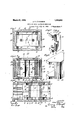
In the drawings, forming apart'of' this specificati'on; Figii1'e' 1 is a'longitudinal,
- horizontal,sectionalview of a railway draft;
rigging showingmy improvements in connection therewlth. F gures Q'and 3 are transverse, vertical, sectional yiews of the.
shock absorbing mechanism proper, corre sponding respectively to the l nesi2e2 and 3 3-ofFigure1'. Figure 4 is a longitudinal, 1
vertical. sectional View, partly broken away,
showing the central portion of the shock absorbing .inechanism and correspond ng,
substantially,- to the, line 4+4 off-Figure 1; Figure 5 detail, perspective'view of one of the wedge friction shoes used in conn ec tion with my ;improyed mechanism, 'And Figure 6' is 'a detailed; perspeetive view of one of the. wedge members employed in" my improved mechanism, i f
In. said drawin I0 10ind icate channel shaped. enter. or, draft sills; of arail way car unj toth inner T of whi h aresecured front stop l'ug's ll ll and rear stop lugs 12412; A portion of the drawbar' "Thefront andrear follower casings,
which. areof like design; are of rectangular box-like construction 'open at their inner ends. comprising spaced longitudinally disposed top and, bottom wall s'16 16 ,"Spaced, longitudinallydisposed side walls 17.17 and a transverse, "vertically. disposed end wall 18. The top; bottom and side walls are reduced iir'thickness at their inner ends,as
' shown at '19 thereby providing continuous abutment shoulders 20. The transverse end wall 18 0f eachcasing is provided'with a pair of inwardly projecting hollow, spaced, I
bosses: 2 1 ffor ,a purpose hereinafter described.
The friction shell- B", whichis also of hollow box-like form, is provided with' longitudinally disposed, spaced top and bottom' walls 22 22 and spaced, longitudinally disposed side walls '23''23; the shell being open at its opposite ends. Midwaybetween the endsofthe shell, each sidewall isinwardly offset indicated at 24-, the inner surface of the offset portionpresenting a relatively short; longitudinally disposed, friction surface 25. adapted to cooperatewith the outerni'o'st group of plate of thencorresponding pla 'E. The opposite ends of the friction sliel'l are ad'apted to telescopically receive; the
The front and rear wedge members C are of like construction, each comprising a main block-like portion 26 and top and bottom,.
horizontally disposed, plate-like flange sections 27'27. Each of the wedge members is provided with a pairof inwardly converging wedge faces 2828 at the inner end thereof, the wedge faces 28 being disposed on opposite sides of the central axis of the mechanism, and each-adapted to cooperate with one of the friction wedge shoes D. The body portion of each wedgemeniber is also provided with afiat end face 29 adapted to form an abutment for the corresponding spring follower plate F. The top and bottom flange sections 27 of'each wedge member embrace the corresponding spring followerand have their extreme outer ends slightly spaced from the inner ends of the corresponding top and bottom walls of the adjacent follower casing A, as clearly shown in Figure 1. The space between each wedge member C and corresponding follower casing A permits of a predetermined amount of initial compression ofthe mechanism, after which the inner end of the follower casing A positively engages with the corresponding wedge C to actuate the latter.
The friction wedge shoes D are number, arranged in pairs, cooperating with the corresponding wedge members C. The shoes D are all of like construction, each shoe comprising a vertically disposed, heavy plate-like section 30 and horizontally dis: posed top andbottom flanges Ell-31 The flanges 31, as clearlyshown in Figures 2 and project outwardly from the plate section 30 and are offset, as shown, presenting transverse-abutment faces 32 and shoulders 33 at right angles thereto. On the inner side, the top and bottom flanges 31 of each shoe D are cut away to present wedge faces 128 correspondingly inclined to, and adapted to cooperate with, one of the faces 28 of the corresponding wedge member C. The top and bottom flanges 31 of the shoes are adapted to embrace the corresponding group of friction plates E, a shoe D being disposed at each. end of each group of plates.
The friction plates E comprise two groups disposed at opposite sides of the mechanism, each .group cooperating with the interior friction surface25 of the shell B. Each group is composed of six like plates. As clearly shown in Figure'et, each plate E is provided with apair of top and bottom lugs 34-34 near one end thereof, the lugs being slightly inset from said end. Alternate plates of each group are similarly arranged,
four in The springresistance elements comprise twin sets in tandem arrangementthat is,
the springs arearrangedinfront and rear sets, in longitudinal alinement, similar to, the arrangement of the usual tandem spring gear, so that when the follower casings are moved toward each other the front and rear springs will be simultaneously compressed and each spring will becompressed to the extent of relative movement of the follower casings. Each twin' arrangedset of springs is disposed within one of the follower casings'and is interposed between the same and-the corresponding spring follower plate F. Each unit of the twin-spring members comprises an outer; relatively heavy coil having its outer end bearing on theend wall of the corresponding follower casing Aand its inner end bearing on the flat outer face of the corresponding spring follower F, and an inner, relatively light coil, having its outer end bearing on the corresponding-o hollow boss 21, of one of the casings A and the corresponding 7 inner surface of the spring follower F. In this connection, it will be notedvthat the twin springs maintain 'eachespring follower F in abutment with the outer transverse face 29 of the corresponding wedge C and bearing on the outer ends of three alternate plates of each group of plates E. V
Theretainer bolts H which are-disposed at opposite sides ofthe longitudinal centre line ofthe mechanism, have their opposite ends anchored respectively in the corresponding bosses ofthe front and rear casings A. The retainer boltsserve'to main tain the parts ofthe mechanism assembled and also hold them under 'initial compres sion, i
As wear occurs on the various friction and wedge faces, compensation therefor is had by the expansion of thetandem arranged springs, which as herein'before pointed out are under initial compressiomfhe 'wedge friction shoes beingadapted to be forcedjoutwardly of the mechanism, proper clearance being provided between the outer ends of the same, the corresponding ends of the plates carried thereby and the adjacent spring follower, to permit of this movement.
The operation, of the improvedv shock absorbing; mechanism is as. follows, assuming.
anm'wmu or bu'ifiiigmoveinent of thedrawbar; A's thedra'wbar -13 moves'inwardly, the
spring follower I1 rearwardly, carryingthe plates engaged thereby and the front wedge 1 G therewith, the said plates in turn carrying the-rear pair of shoes rearwardlyand forcingfthem against-therear wedge G, movement of'the latter-being yieldingly resisted by the rear spring-follower, which in turn is also forced rearwardilyby' theremaining friction plates, the latter being actuated by the front pair of shoes which. are forced rearwardly-bythe front wedge GQ Due to the friction resistance between the plates of the two groups and the shell B, the latter will becarried rearwardly. with the plates. The front andrear spring followers, frontv and rear--wedges,- front "andrear pairs of shoes, t-wo groups of plates and the shell B will move: as a unitj also compressing the twinsprings G disposed within the rear follower casing Itwill be evident that a' wedging action is also set up between the main wedges C and the: correspondingjpairs' of friction wedge shoes D during theaction j ustd escri-bed, placing'the friction plates under pressure and "forcing the. same against the shell walls. The relative approachof' the front and rear follower casings A will continue until the innerendsof the respec tive follower casings come into 'abutment with the outer ends of the front. and rear wedge members C, respectively, whereupon the wedge'members C will'bemoved rela-. tively toward each other, unison with the follower casings,eife'cting relative movement.
of the frontand rear pairsofjfrictionwedge shoes D. A's alternate plates;o f 'eaicli gronp are anchored to the front friction shoes, and
the n n p at bf' he spee i le ever-P i re I e i hb e to t e t ar Pei- Qi iic wedge shoesD, the plates of'the two groups will be movedrelatively' toeach other,gr.eat -1 ly augmenting the frictional resistance. At the same. timenthe front-and rear spring followers 1? will be forced apart by theiielar tively movab;le plates, further compressing, I
' G" 'dem arranged springs interposed between the front and rear setsjof'twin; spr ngs This action continues until :the outer end's of the shell B and t he shoulders 20;: of the front and rear follower casings'come into abut ment, whereupon the forces will be transmitted directly through the casings andthe shell to the rear stop lugs, as hereinbefore pointed out, thereby. preventing-the springs from. beingdriyen solid. During draft, the n s s bstant al y e ev rse 9 that inst describednthe front ifollower casing A g dstti nary hi ef he 'ea iollower 'casfinge is; vedila iy y,tli r te- In release, the twinarranged 'springsat the which in" turn force the front;
front and rear end of the 1 mechanism arefree'to expand immediately upon the reduc tion of pressure, and return the front and rear-follower casings to theirnormal posi tion independently'of any releasing action ofthe frictio'nj'wedge system. During the restorationof the front and rear follower casings, the inner ends of the same will be movedfaway from the cooperating ends of the wedge members C,thereby relieving the same of direct pressure from the follower casings, reducing, the wedging pressure to permit release of the parts of the mechanism. 7
Expansion of the front and rear sets of springs will carry the corresponding frontv and rear spring followers inwardly moving the corresponding plates therewith, which in turn carry the shoes anchored thereto outwardly, forcing the correspondingwedge C outwardly also, until movement of the lat.
ter is" arrested" by engagement with the in- 'ner face of the correspondingspring follower.
It will, evident that main spring followers is positivelyassured, but that". the tandem arranged springs may function substantially independently of the wedge friction system, thatis, if the friction wedge system "should become jammed or stuekfor any reason, the front and rear twin springs are available after each'compression stroke to restore. the front and rear casings the tandem springs from opposite ends, thereby greatly increasing the spring capacity of the gear.
x v by iny iniproved' arrangement, not only restoration of the Ihave herein shown andj described what I I. now 1 consider the preferred manner of carrying ont the invention, but, the same is merely illustrative and I] contemplate all changes and .modification's that come. Within the scope of the claimsap pended hereto.
l'ycla imf 1; In a friction shoclr' absorbing mechanisni, the combinatirm with front and'rear vfollower acting elements, relatively movable toward and: away from each other; of tansaidj elements and friction means interposed between sa d tandem arranged spr ngs, said means including two sets of relatively movable friction plates and pressuretransmitting members interposed betweeneach of said follower eleinentsand, one ofsaidsets of plates, sa d se'ts of plates cooperating re spec-tlvely with the tandem arranged spr ngs and rear spring resistance elements arranged nism, the combination with front and rear follower acting means, relatively movable toward and away from each other; of front in tandem, said front and rear spring elements being interposed between said follower-acting means, one of said spring elements being acting means; and pressure transmitting means interposed between each followeracting means and the inner end ofthespring resistance element associated with the other follower-acting means, each pressure transmitting means including a plurality of friction plates, said plates of eachpressuretransmitting means cooperating with the corresponding platesof the other pressure transmitting means.
3. In a friction shock absorbing mocha-V 1 nism, the eoinbinationw th front and rear follower acting members, relatively movable toward and away from each other; of front andrear spring elements interposed between said follower-acting members; a plurality of relatively movable, longitudinally disposed,
interealated friction plates interposed b ethe respective follower-acting members; and I means for effecting relative movement of said plates upon relative movement of said systems.
t. In a friction shock absorbingniechm 'I'liSlI], the combination with front and rear follower acting members, relatively movable toward and away from each other; of front and rear spring elements interposed between said follower-acting members; a friction shell interposed between said follower-act ing members, said shell having longitudinally disposed interior frictlon surfaces; a
plurality of relatively movable, longitudi;
nally disposed, interealated friction plates interposed between said front and rear spring elements and disposed within said shell, said plates being divided into groups disposed at opposite sides of the mechanism, each group comprising two sets ofrelatively movable plates, one set having its movement opposed by one of said spring elements and the other set having its movement opposed by the other spring element; spreading 'ineans between said group of plates for forc-.
ing the same against the friction surfaces of the shell, said spreading means including a pair of wedge shoes and a cooperating wedge member at opposite ends of said plates, said wedge members being actuatedrespectlvely associated with each followers,
bers; and cooperating means on said shoes:
and plates for effecting relative movementof said sets ofplates. v
5. In a friction shock absorbing. mechanism, the combination with frontv and rear followers, relatively movable toward and away from each other; of tandem arrangedsprings interposed between said followers;
and means interposed between said springs, and cooperating with the inner ends thereof,: actuated by relative movement of: said fol-v lowers for forcing said springs apart, said means including a plurality of relatively movable friction plates;
[61in a friction shock absorbing mechanisin, the combination with front andrear followers, relatively movable towardand awayfroin each other; of front and rear spring elements interposed between saidfollowers, one of said spring elements bearing.
on eachfollower; a wedge pressure transmitting member cooperating with each fol:
lower, a friction wedge shoe coacting with each wedge pressure transm tting member' a lateral pressure, resisting member coop-- crating with'said shoes and friction means carr ed by each of said shoes for transmitting the pressure from one of said followi ers to the inner endof the spring element bearing on the other follower, said friction means of each shoe cooperating with the friction means of the other shoe. i
7. In a friction shockabsorbing mechanism, the combination with frontand rear followers; of a friction shell interposed be tween said followers, said shell having lonthe front and rear follower actingniem l (lD gitudiiially disposed, opposed interior frictioii surfaces; a group of intercalated friction plate-s cooperating with each shell fries tion surface, each group comprising two, sets of relatively movable friction plates; means for forcing said groups of plates against the respective friction surfaces, said ineansineluding wedge members coacting with each shell and a pair of fr ction shoes coacting with each wedge member; one pair ofshoes coasting with one wedge member having en gagement with correspond ng ,QILClS' of one setof plates and the other pair of shoes haw ingengagement with the corres oncling ends of the other set of plates; and yielding movement resisting means interposed,betwcenc the remaining endsof each set of plates and l the follower at the corresponding-end of the mechanism.
SJIn a friction shock absorbing mechanism, the combination with front and rear followers; of a fr ction shell nterposed between said followers. said shell having longitudinally disposed interior surfaces; front and rear wedge members adapted to be ac-- tuated by the respective followers; frontand rear pairs of Wedge friction shoes c0-- operating with the respectivefollowers: a
group of friction plates interposed between each interior surface of the shell and the friction wedge shoes on the corresponding side of the mechanism, each group comprismg relatively movablesets of plates, one set being anchored to the front shoes and the other set to the rear shoes at the correspond nism, the combination with front and rear followers, of a friction shell interposed be tween said followers, said shell having its opposite ends normally spaced from the re spective followers, and being provided with longitudinally disposed interior friction surfaces; front and rear wedge members adapted to be actuated by the respective followers, said wedge-members being normally slightly spaced from said followers to permit preliminary action of the mechanism; front and rear pairs of wedge friction shoes cooperating with the respective followers; a group of friction plates interposed between each interior surface of the shell and the friction wedge shoes on the corresponding side of the mechanism, each group comprising relatively movable sets of plates, one set being anchored to the rear shoes and the other set to the front shoes at the corresponding side of the mechanism; and front and rear spring resistance elements opposing movement ofvthe respective sets of plates and coacting with the'front and rear followers respectively.
' 10. In a friction shock absorbing mecha nism, the combination with front and rear followers, of a friction shell interposed between said followers, said shell having lon gitudinally disposed, interior friction surfaces; front and rear sets of twin arranged springs interposed between said followers; two series of longitudinally movable plates, the plates of said two series being intercalated and each series of longitudinally mov- I able plates cooperating with the inner ends of one of the sets of twin springs; a friction shoe having engagement with each set of plates to effect movement of the same; and a wedge engaging each friction shoe and c0- operating with one of said followers.
11. In afriction shock absorbing mechanism, the combination with front and rear followers, of a friction shell interposed between said followers, said shell having longitudinally. disposed, interior friction surfaces; front and rear springs interposed between said followers; a springfollower cooperating with the inner end of each of said springs; a plurality of relatively movable friction plates interposed between said spring followers, the front ends of alternate plates engaging one ofsaid spring followers and the rear ends of the remaining plates engaging theother spring follower; and means for moving said plates relatively to each other and placing the same under lateral pressure, said means including wedge members adapted to be actuated by the front and rear followers respectively and friction shoes cooperating with said wedge members, each of said shoes being operatively con nected to certainof the friction plates; 12. In a friction shock absorbing mechanism, the combination with front and rear followers, of tandem arranged spring elements interposed between said followers, saidelements having theirouter ends cooperating with the respective followers; and means for transmitting pressure from the front and rear followers to the inner ends of said spring elements respectively, said m-eans'including relatively movable friction plates, andmeans actuated by the respective followers for placing said plates under lateral pressure and moving the same relatively to each other longitudinally of the mechanism.
In witness that I claim the foregoing I have hereunto subscribed my name this 9th day of July, 1924.
JOHN F. OCONNOR.
Priority Applications (1)
| Application Number | Priority Date | Filing Date | Title |
|---|---|---|---|
| US727109A US1663993A (en) | 1924-07-21 | 1924-07-21 | Friction shock-absorbing mechanism |
Applications Claiming Priority (1)
| Application Number | Priority Date | Filing Date | Title |
|---|---|---|---|
| US727109A US1663993A (en) | 1924-07-21 | 1924-07-21 | Friction shock-absorbing mechanism |
Publications (1)
| Publication Number | Publication Date |
|---|---|
| US1663993A true US1663993A (en) | 1928-03-27 |
Family
ID=24921371
Family Applications (1)
| Application Number | Title | Priority Date | Filing Date |
|---|---|---|---|
| US727109A Expired - Lifetime US1663993A (en) | 1924-07-21 | 1924-07-21 | Friction shock-absorbing mechanism |
Country Status (1)
| Country | Link |
|---|---|
| US (1) | US1663993A (en) |
-
1924
- 1924-07-21 US US727109A patent/US1663993A/en not_active Expired - Lifetime
Similar Documents
| Publication | Publication Date | Title |
|---|---|---|
| US2184936A (en) | Cushioning mechanism | |
| US1663993A (en) | Friction shock-absorbing mechanism | |
| US1364511A (en) | Friction shock-absorbing mechanism | |
| US2720320A (en) | Combined friction and rubber shock absorbing mechanisms | |
| US1765875A (en) | Friction gear | |
| US1905492A (en) | Shock absorbing mechanism | |
| US1689451A (en) | Friction shock-absorbing mechanism | |
| US1329795A (en) | Shock-absorber | |
| US1640214A (en) | Friction shock-absorbing mechanism | |
| US1232321A (en) | Friction-gear. | |
| US1667798A (en) | Friction shock-absorbing mechanism | |
| US1650439A (en) | Friction shock-absorbing mechanism | |
| US1682042A (en) | Friction shock-absorbing mechanism | |
| US1673372A (en) | Friction shock-absorbing mechanism | |
| US1865838A (en) | Draft gear | |
| US1689449A (en) | Friction shock-absorbing mechanism | |
| US2810484A (en) | High capacity draft gear with friction and a plurality of spring cushioning elements | |
| US1571679A (en) | Friction shock-absorbing mechanism | |
| US1959582A (en) | Friction shock absorbing mechanism | |
| US1363006A (en) | John i | |
| US1637070A (en) | Friction shock-absorbing mechanism | |
| US1355995A (en) | Friction draft-rigging | |
| US1758966A (en) | Friction shock-absorbing mechanism | |
| US1871420A (en) | Shock absorbing mechanism | |
| US1844238A (en) | Draft gear |