US1663806A - Boiler - Google Patents
Boiler Download PDFInfo
- Publication number
- US1663806A US1663806A US1663806DA US1663806A US 1663806 A US1663806 A US 1663806A US 1663806D A US1663806D A US 1663806DA US 1663806 A US1663806 A US 1663806A
- Authority
- US
- United States
- Prior art keywords
- water
- boiler
- firebox
- tables
- steam
- Prior art date
- Legal status (The legal status is an assumption and is not a legal conclusion. Google has not performed a legal analysis and makes no representation as to the accuracy of the status listed.)
- Expired - Lifetime
Links
- XLYOFNOQVPJJNP-UHFFFAOYSA-N water Substances O XLYOFNOQVPJJNP-UHFFFAOYSA-N 0.000 description 107
- 238000002485 combustion reaction Methods 0.000 description 57
- 230000003137 locomotive effect Effects 0.000 description 42
- 239000003921 oil Substances 0.000 description 24
- 239000000446 fuel Substances 0.000 description 20
- 239000011449 brick Substances 0.000 description 16
- 239000003245 coal Substances 0.000 description 14
- 239000000295 fuel oil Substances 0.000 description 12
- 238000005266 casting Methods 0.000 description 8
- 239000010425 asbestos Substances 0.000 description 7
- 230000015572 biosynthetic process Effects 0.000 description 7
- 229910052895 riebeckite Inorganic materials 0.000 description 7
- 238000010276 construction Methods 0.000 description 6
- 238000001704 evaporation Methods 0.000 description 6
- 238000010438 heat treatment Methods 0.000 description 6
- 239000002184 metal Substances 0.000 description 6
- 229910052751 metal Inorganic materials 0.000 description 6
- 238000003466 welding Methods 0.000 description 6
- 210000003739 neck Anatomy 0.000 description 5
- 238000012856 packing Methods 0.000 description 5
- 229910001208 Crucible steel Inorganic materials 0.000 description 4
- 230000006978 adaptation Effects 0.000 description 4
- 238000006243 chemical reaction Methods 0.000 description 3
- 238000004891 communication Methods 0.000 description 3
- 235000000396 iron Nutrition 0.000 description 3
- 241001304230 Progne cryptoleuca Species 0.000 description 2
- 238000009825 accumulation Methods 0.000 description 2
- 230000008602 contraction Effects 0.000 description 2
- QFXZANXYUCUTQH-UHFFFAOYSA-N ethynol Chemical group OC#C QFXZANXYUCUTQH-UHFFFAOYSA-N 0.000 description 2
- 238000005304 joining Methods 0.000 description 2
- 238000012423 maintenance Methods 0.000 description 2
- 239000007787 solid Substances 0.000 description 2
- 239000004449 solid propellant Substances 0.000 description 2
- 229910000746 Structural steel Inorganic materials 0.000 description 1
- 210000001015 abdomen Anatomy 0.000 description 1
- 230000003190 augmentative effect Effects 0.000 description 1
- 238000004140 cleaning Methods 0.000 description 1
- 238000005520 cutting process Methods 0.000 description 1
- 230000008021 deposition Effects 0.000 description 1
- 238000013461 design Methods 0.000 description 1
- 238000004821 distillation Methods 0.000 description 1
- 230000000694 effects Effects 0.000 description 1
- 238000003780 insertion Methods 0.000 description 1
- 230000037431 insertion Effects 0.000 description 1
- 238000012986 modification Methods 0.000 description 1
- 230000004048 modification Effects 0.000 description 1
- 230000003014 reinforcing effect Effects 0.000 description 1
- 238000005406 washing Methods 0.000 description 1
Images
Classifications
-
- F—MECHANICAL ENGINEERING; LIGHTING; HEATING; WEAPONS; BLASTING
- F22—STEAM GENERATION
- F22B—METHODS OF STEAM GENERATION; STEAM BOILERS
- F22B13/00—Steam boilers of fire-box type, i.e. boilers where both combustion chambers and subsequent flues or fire tubes are arranged within the boiler body
- F22B13/06—Locomobile, traction-engine, steam-roller, or locomotive boilers
Definitions
- the hereinafter described invention relates to improvements in boilers and more particularly to the boilers of the locomotive or firebox type in which the fuel is injected through a burner such as fuel oil or powdered coal; being distinguished from the burning of coal or solid fuel on a grate in which the heat of combustion as evolved from the products of distillation of the coal is imparted to or acts against steam generating surfaces of the firebox combustion chamber above the hot fuel bed in that I make available as steam generating and water circulating surfaces in the combustion chamber of an oil burning locomotive boiler the plain metallic, refractory covered nonsteam generating surfaces as now installed below the grate bar and coal bed in converting the firebox of a coal burning locomotive to burn fuel oil, by causing the heat of combustion to act against such surfaces.
- a further object of my invention is to expeditiously convert the firebox of a coal burning locomotive boiler with mud ring forming the end thereof into a combustion chamber for burning fuel oil or other injected fuel by removing a relatively small portion of the inside sheets of the firebox adjacent the mud ring and running longitudinally on either side of the firebox and substituting in place of the sheets removed, preferably by electric welding, water carrying surfaces which in factwhen the heat of combustion plays thereagainst form steam generating surfaces and in a manner so that the mud ring of the firebox remains intact or positioned as originally constructed and so that should it be desired for reasons of fuel economy to again re-convert the locomotive to burn coal that such conversion can be uickly made by simply cutting the water surfaces or tables out, preferably with an electric or oxyacetylene torch, and installing plates substantially of like dimensions as those removed by welding them into place after attachment to the mud ring in the same maner as originally installed, thereby mak ing it possible to inexpensively and expeditiously convert a coal burning fire
- Another object of my invention is to form the bottom of a firebox combustion chamber of an oil burning locomotive boiler with water evaporating tables so that the play of the flame of the boiler will contact the table, and to lead the water of the boiler into the tables continuously from a point preferably in the shell of the boiler beyond the confines of the water space surrounding the firebox proper and in such a manner, in fact, as to insure their constant supply with Eli rapidly circulating boiler feed water in cf footing the generation of steam over their surfaces.
- Another object of my invention is to create and put into effect an improved oil burning or injected fuel burning locomotive bo ler through the provision of water Qirculating steam generating tables forming the bottom of the fire-box combustion chamber thereof.
- A. further object of my invention is to form a steam generating bottom for an injected fuel burning locomotive boiler of elements secured to the side sheets of the firebox of the boiler adjacent the mud ring thereof and without disturoance of the mud ring and so that the elements will be connected to a source of water supply from the boiler.
- a further object of my invention is to provide the combustion chamber. of a locomotive oil burning or injected fuel burning boiler so that the elements forming its bottom will be steam generating tables and to so house such elements with metallic plates that refractor burner and flash end walls, as well as refractory bottom, can be installed. in the combustion chamber without materially detracting from the steam generating tables as initially welded into place in the firebox and so that air for combustion can be supplied into the combustion chamber.
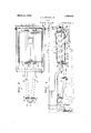
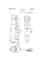
- Fig. l is a side elevation partly in section of the rear or the box end of a locomotive boiler wherein the improvements of my invention are carried out.
- This assembly view shows generally the complete metallic structure of my invention with the steam generating tables forming the bottom of the combustion chamber of an oil burning locomotive boiler as welded in place and joined at their front ends through pipe connections with the belly of the boiler.
- the metallic housing of the water evaporat ing elements in the formation of the oil burning combustion chamber is shown with the fuel oil burner in place, but without the refractory bricks in the combustion chamber.
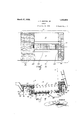
- Fig. 2 is a plan view of Fig. 1 showing the combustion chamber partly in section with pipe connections to the steam generating tables, both of which in this instance re ceive water from the shell of the boiler through separate pipes connected to a common header secured to the bottom of the boiler shell.
- the rear ends of the steam generating elements are shown with blowofi connections for the removal of encrustatingr matter and mud therefrom.
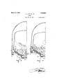
- Fig. 8 is an. end elevation partly in sectionof the firebox end of my improved injected fuel burning locomotive boiler the essence the firebox just above the mud ring thereof the tables opening into the water legs and being staybolted in like manner as the water legs.
- the exterior part shows the metallic housing around the steam generating tables in the formation of the oil burningcombustion chamber and also shows the blow-off pipe connection from the steam genera 1mg elements.
- Fig. 1- is an enlarged sectional view of a portion of the firebox of my improved construction, adjacent the mud ring thereof to further illustrate how the steam generating elements are flanged or shaped for attachment to the inside sheets of the firebox, fori'ning as they do upon welding to the side sheets substantially a continuation thereof.
- the plate forming the bottom housing of the oil burning combustion chamber between the two bulbous ends of the steam generating tables is shown with asbestos tight joint a gainst the bulb of the table while a bracket is shown under the bulbous end to assist generally in supporting the steam generating tables, as well as to support the metallic housing forming the oil burning combustion chamber in carrying the load of refractory bricks placed therein.
- FIG. 5 is a sectional view of a portion of the end of the steam tables showing their metal plate structure welded together at the rounded ends and with asbestos tight joints between it and the sheet metal housing secured by studs welded thereto as required in the formation of t e combustion chamber of my improved boiler.
- Fig. 7 is a sectional elevation of the fire box combustion chamber of my improved injected fuel locomotive boiler arranged to show the manner of placing the refractory bricks therein, the oil binner, openings for admittance of air for combustion, and more particularly to show the steam generating tables in place and disclose prominently their exposure, bylack of refractory covering, to the heat of combustion and radiant heat; these surfaces, in fact, now being formed of plain metal sheets or surfaces which are covered with refractory bricks in making the firebox combustion chamber of present oil burning locomotives.
- Fig. 8 is a plan view of Fig. 7 looking down into the combustion chamber to illustrate the placement of the refractory bricks therein and to accentuate the fact that the bottom of the combustion chamber in my new and novel construction now exposes water evaporated surfaces heretofore unavailable for steam generation by being covered with refractory to prevent their plain metallic surfaces from burning out.
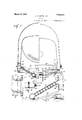
- Fig. 9 is a sectional end elevation of half of the full firebox combustion chamber with water and steam space surrounding same, this illustration of my improved construction being taken on line 99, Fig. 7, looking toward the oil burner and showing the burner refractory end wall.
- Fig. 10 is a sectional end elevation of half of the full firebox combustion chamber with Water and steam spaces as provided by my steam generating tables in conjunction with the water legs of the boiler, looking toward the rear end of the combustion chamber, being taken on line 10-10, Fig. 7, and showing the refractory flash wall of the oil burning combustion chamber.
- Figs. 11, 12 and 13 show in general assembly the full adaptation of my invention to the locomotive, being a side elevation, plan and rear end view, respectively and illustrating diagrammatically by arrows the flow of course of the water from the boiler through the inlet connections to the steam enerating tables and the circulation effected by the tables through the water legs into the boiler.
- My principal object, as heretofore stated, is to provide for the generation of steam be low the mud ring of the firebox or the normal location of a hot coal bed on a grate bar, in the formation of the combustion chamber of an oil burning or an injected fuel burning locomotive, causing the play of the flame and its radiant heat aided by the hot refractory surfaces of the combustion chamber, to act against rapidly circulating water with- .in surfaces forming the bottom of the combustion chamber.
- numerals 10 and 11 designate the steam generating tables as welded to the'inside firebox sheets 12 and 13, being denoted by the word weld, Figs. 1, 3, 4, 9 and 10 of the drawings, after removal of a longitudinal strip of the sheets 12 and 13 on either side of the firebox just above the mud ring 14 thereof; the strips of sheet removed being approximately 12 inches high by the total length of the steam table units and in case of removal for the insertion of the units as in the conversion of locomotives already constructed the strips of sheet are readily cut out by oxyacetylene or electric torch.
- the steam generating units 10 and 11 formed generally as shown, are welded in place to the side sheets 12 and 13, respectively, at their upper flanged and filleted ends 15 and 16, respectively, and secured to the mud ring 14 through their lower flanged and filleted ends 17 and 18, respectively, in like manner of fastening the side sheets 12 and 13 originally thereto, the bottom edges of the flanged and filleted ends 17 and 18 being beveled and caulked against the mud ring 1 1 for steam tightness in accordance with regular defined practice.
- the side sheets 12 and 13 are of course formed short of the mud ring 1% and the tables welded directly thereto and secured to the mud ring in like manner as above.
- the steam generating tables 10 and 11 are in the present showing made substantially counterparts, except one is made right and the other left, and are approximately rectangular in shape; being four sided and in the present showing rhomboidal on account of ill) am :aeeaaoe the sloping mud ring of the firebox,
- the water space provided between the formed sheets of which they are comprised is ap proximately? inches wide inside of sheets and staybolted, as are the water legs of the boiler, with solid and flexible staybolts in accordance with well-defined practice, meet ing Federal and State boiler requirements.
- the tables as shown, are made with bulbous bottoms or terminuses and their siects worked out as at 19 to connect circular flanges 20, 21, 22 and 23 thereto preferably by riveting and welding; being illustrated in larger scale by Fig. 6.
- the flanges are all 6 inch cast steel extra heavy templet, the flanges 20 and 21, being connected by companion flanges 24; and 25 to two 6 inch extra heavy pipes and 27, respectively, leading into the cast steel Y header 28 and the flanges and 30 on the header casting 28 being connected by companion flanges 31 and 32 to the pipes 26 and 27, respectively.
- the header 28 is cared to the bottom of the boiler shell by flange 33, preferably in advan e oi the firebox flue sheet of the boiler.
- the pipes 26 and 27 deliver boiler water continuously into the steam generating tables 10 and ll, the steam being rapidly formed and coursin through the tables and up the water legs or the boiler and back into the boiler, the continual circulation and flow of water and steam through the boiler maintainingthe metallic sheets thereof at a more generally uniform temperature throughout than has heretofore been possible in an oil burning locomotive firebox boiler and consequently causing a more equal expansion and contraction of the boiler plates, which materially increases their life and resistance to the high duty service obtaining.
- the flanges 22 and 23 which it will designate as the rear flanges of the steam generating tables 10 and 11 provide attachment for the cast steel headers or ends 3stand 35, respectively, through companion header flanges 36 and 37. respectively.
- the flanges 22, 23, 31 and 32 are all 6 inch cast steel extra heavy templet, the same as the flanges 20, 21, 24c and 25, thereby making all flange connections interchangeable.
- Leading from the headers 34: and 35 are the bottom blow-oil pipes 38 and 39, respectively;
- blow-oil coclrs a0 and 41 blow-oil coclrs a0 and 41, respectively.
- the end plates 45 and d6 are cut out and angle irons fitted thereto to "form around the top halves of the necks of the steam generating tables 10 and 11 just back of the'fianges 20 and 21, and 22 and 23, respectively, and likewise front and rear end castings l9 and 50, respectively, tightly secured to the ends of bottom plate 12, are made with cut out flanges to form around the bottom halves of the necks of the steam generating tables 10 and 11 just back of the flanges 20 and 21, and 22 and 23, respectively, so that the asbestos sheet packing 51 interposed.
- any equivalent combustion chamber housing to that shown and described may be made by plates, angle irons, castings or other structural shapes arranged with joint forming means therebetween and the steam generating tables and firebox surfaces.
- Numeral 57 denotes the front or burner refractory end wall and 58 the flash or rear refractory end wall.
- the front plate 52 is completely covered with fire bricks 59, the same carrying clear across to the side sheets and front sheet of the firebox, while the rear plate 55, is covered with fire bricks 60 fitted between the flash end wall 58, and the door sheet of the firebox and running clear across the firebox against the side sheets thereof, these refractory or fire brick coverings being best shown in plan view, Fig. 8.
- the bottom plate 42 is provided with an air opening 61 for the admittance of air for combustion and is refractory lined with fire brick 62, the same abutting the burner and flash end Walls 57 and 58, respectively, as well as the sides of the bulbous ends or bottoms of the steam evaporating tables 10 and 11, and forming around the air opening 61.
- the burner 63 is shown in place delivering fuel oil through the casting 64, secured to the burner end plate 45, the casting 64 provid ing for the admittance of air around the burner.
- Air is brought into the opening 61 through the hopper 65, secured to the bottom of plate 45.
- Brackets 66, secured to the mud ring 14, are used as occasion demands to assist in supporting the steam evaporat ing tables 10 and 11, as well as the combustion chamber housing and the refractory bricks placed therein.
- Washout plugs 67, 68 and 69 are provided in the pipe lines 26 and 27 and at the ends of the steam generating tables 10 and 11 at 70 and 71 in the end headers 3e 35, respectively, for the par pose of readily washing out and cleaning the pipes and steam tables of sedimentary accumulation from the boiler feed water.
- the structure of my improved locomotive boiler does not entail other than standard and well-defined practice in the assembly of its parts, such, in fact, as is daily encountered in locomotive practice, forming as it does a simple and efiicient construction throughout.
- the water from the boiler feeds continuously through the pipes 26 and 27 into the front ends of the steam generating tables 10 and 11, respectively, and courses upwardly through the tables into the water legs of the boiler just above the mud ring thereof.
- the bubbles of steam generated by the hot products of combustion emitted from the fuel oil burner 63 contacting the exposed surfaces of the tables cause a rapid circulatory movement of the water and steam up the water legs, around the crown sheet and back again into the boiler; being, in fact, a continuous steam and water movement through the steam generating elements providing the bottom of the combustion chamber.
- a locomotive fire tube boiler including a barrel and a firebox having water legs a water bottom for side firebox carried by the side sheets thereof and communicating with said water legs and a water passage from the barrel to said bottom providing for the flow oi water from the barrel through. said bottom into said legs.
- a locomotive fire tube boiler including a barrel and a firebox having water legs terminating in a mud ring; a downwardly and inwardly inclined water bottom depend ing below the mud ring and communicating with said water legs closely adjacent said mud ring, a passage for water from the bar rel communicating with the lower portion of said bottom providing circulation. through said bottom into said legs.
- a locomotive fire tube boiler including a barrel and a fire-box having water legs terminating in a mud ring, a water bottom for said firebox comprising a pair of downwardly and inwardly sloping water holding units spaced apart at their lower portions, the interior of each unit communicatingwith the interior of the corresponding water leg closely adjacent the mud ring, a passage for water from the barrel to the lower portion out each unit providing for flow of water from the barrel through said units into said legs.
- a locomotive fire tube boiler including a barrel and a firebox having water legs terminating in mud ring, downwardly and inwardly inclined hollow quadrangular shaped water tables forming a water bottom for the firebox, depending below the mud ring thereof and communicating with said water legs closely adjacent said mud ring, a passage ii'or water from the barrel communicating with the lower portion oat said bottom providing for flow of water from the barrel through said bottom into said legs.
- a locomotive fire tube boiler including a barrel and a firebox having water legs terminating in amud ring, downwardly and inwardly inclined hollow quadrangular shaped water tables terminatingin reservoirs and forming a water bottom for the firebox, depending below the mud: ring thereof and communicating with said water legs closely adjacent said mud ring and a water passage from the barrel to said reservoirs providing" for the flow of water from said barrel through said bottom into said water legs.
- a locomotive fire tube boiler includ ing a barrel and a firebox having water legs terminatingin a' mud ring, downwardly and inwardly inclined hollow quadrangular shaped water tables dependingbelow the.
- a locomotive fire tube boiler including a barrel and a firebox having water legs terminating in a mud ring, a water bottom comprising hollow quadrangular shaped tables formed with upper and lower walls the upper walls connected to the side sheets he firebox and the lower walls connected to the mud ring thereof providing free open communication between said tables and. said water legs, a water passage from the barrel to said tables providing for flow of water through said tables into said water legs.
- a locomotive fire tube boiler includ. ing' a barrel and a firebox having" water legs terminating in a mud ring, downwardly and inwardly inclined quadrangular hollow, shaped water tables connected to the side sheets of the firebox and joiner to the mud ring thereof, said tables depending below the mud of the firebox and providing open communication substantially their entire length with the side water legs of the firebox, pipe connections joining the bottom front ends of said tables with the barrel, blow oil connections leading ⁇ ; from the bottoms of said tables, a metal housing combining said tables and firebox into a substantially air tight chamber, means for admitting air for combustion into said. chamber, refractory briclr linings covering the surfaces oi" said housing and a burner for heating said tables.
- a locomotive fire tube boiler ineluding a barrel and a firebon having water legs terminating in a mud ring downwardly and inwardly inclined hollow, quadrangular shaped water tables connected. to the side sheets of the firebox and, joined to the mud ring thereof, said tables depending below the mud ring ct the firebox and providing open communication substantially their entire length with the side water legs of the firebox, flanged.
- openings at the bottom front ends of said tables a flanged header secured to the barrehfianged pipe connections joining the flanges of said openings and headen flanged openings the bottom baclr ends ott said t bles flanged headers sccured to said last named flanged.
- openings IOU providing blow off connections, a metal housing combining said tables and firebox into a substantially air tight chamber, means for admitting air for combustion into said chamber, refractory brick linings covering the surfaces of said housing and a burner for heating said tables.
- a steam generating and water circulating element for connection to the water legs of the firebox of a locomotive boiler adjacent the mud ring thereof, comprising a quadrangular shaped, hollow table with staybolted surfaces constructed of a single sheet of plate of like character as the sheets of the firebox and bent so as to form rounded ends and a rounded closed side, the opposite side of the table terminating in a flanged opening running substantially the full length of the table, said flange presenting edges adapted to be welded to the side sheets of the firebox and a face adapted to be secured to the mud ring thereof in steam tight engagement, the closed side and ends of said table at their juncture being formed into openings, reinforcing rings around said openings, said rings providing connections for the inlet of water from the boiler and the discharge of sedimentary matter from the boiler.
- a steam generating and water circulating element for connection to the water legs of the firebox of a locomotive boiler adjacent the mud ring thereof, comprising a quadrangular shaped, hollow table with staybolted surfaces closed on its ends and one side and terminating on its opposite side in a flanged opening running the full length of the table, said flange presenting edges adapted to be welded to the side sheets of the firebox and a face adapted to be secured to the mud ring thereof in steam tight engagement, the closed side and ends of said table at their juncture being flanged out into necks in the provision of an inlet for Water from the boiler and an outlet for sedimentary discharge from the boiler.
- a water circulating and steam generating unit for augmenting the water heating and carrying surfaces surrounding the firebox of a locomotive boiler comprising a hollow, quadrangular shaped table constructed of plates of like character as the sheets of the firebox and staybolted together to form the water carrying walls of the table, in a like manner as the staybolted water legs of the firebox, the ends of the table being closed and one side of the table being open its full length and width and flanged for attachment to the water legs of the boiler adjacent the bottom thereof, providing upon attachment a continuation of the water legs, the opposite side of the table being formed into a closed rounded end running its full length and flanged at its juncture with the closed ends of the tables into openings, one of said openings providing a water inlet from the boiler and the other opening discharge outlet for the removal of sedimentary matter from the boiler.
Landscapes
- Engineering & Computer Science (AREA)
- Chemical & Material Sciences (AREA)
- Combustion & Propulsion (AREA)
- Physics & Mathematics (AREA)
- Thermal Sciences (AREA)
- Mechanical Engineering (AREA)
- General Engineering & Computer Science (AREA)
- Spray-Type Burners (AREA)
Description
March 27, 1928.
J. C. MARTIN. JR
BOILER 5 Sheets-Sheet 1- INVENTOR Filed Nov. 19. 1926 March 27, 1928.
J. C. MARTIN. JR
BOILER Filed NOV. 19. 1926 5 Sheets-Sheet 2 INVENTOR March 27, 1928. 1,663,806
J. c. MARTIN, JR
BOILER Filed Nov. 19. 1926 5 Sheets-Sheet s EEB 6B ,0
March 27, 1928. 1,663,806
J. c. MARTIN, JR
BOILER Filed Nov. 19. 1926 5 Sheets-Sheet 4 March 27, 1928.
J. C. MARTIN. JR
BOILER Filed Nov. 19. 1926 5 Sheets-Sheet 5 z F O Q HHWMJQ 1L INVENTOR Patented Mar. 27, 1928.
UNITED STATES JESSE C. MARTIN, JR., 0}? SAN FRANCISCO, CALIFORNIA, ASSIGNOR TO JOHN MORRIS, OF
PATENT ()FFICE.
LOS ANGELES, CALIFORNIA.
BOILER.
Application filed November 19, 1926. Serial No. 149,865.
The hereinafter described invention relates to improvements in boilers and more particularly to the boilers of the locomotive or firebox type in which the fuel is injected through a burner such as fuel oil or powdered coal; being distinguished from the burning of coal or solid fuel on a grate in which the heat of combustion as evolved from the products of distillation of the coal is imparted to or acts against steam generating surfaces of the firebox combustion chamber above the hot fuel bed in that I make available as steam generating and water circulating surfaces in the combustion chamber of an oil burning locomotive boiler the plain metallic, refractory covered nonsteam generating surfaces as now installed below the grate bar and coal bed in converting the firebox of a coal burning locomotive to burn fuel oil, by causing the heat of combustion to act against such surfaces.
Among the objects of my invention is the conversion of the present type of coal burning locomotive firebox with dead or mud ring end forming the bottom thereof into an oil burning or injected fuel burning firebox combustion chamber in a simple, efficient and inexpensive manner, making effective steam generating surfaces of relatively large area hitherto not available by exposing them through my improved construction to the heat of combustion and radiant heat developed within the combustion chamber and causing the rapid generation of steam by the rapid circulation of the boiler water against such surfaces.
A further object of my invention is to expeditiously convert the firebox of a coal burning locomotive boiler with mud ring forming the end thereof into a combustion chamber for burning fuel oil or other injected fuel by removing a relatively small portion of the inside sheets of the firebox adjacent the mud ring and running longitudinally on either side of the firebox and substituting in place of the sheets removed, preferably by electric welding, water carrying surfaces which in factwhen the heat of combustion plays thereagainst form steam generating surfaces and in a manner so that the mud ring of the firebox remains intact or positioned as originally constructed and so that should it be desired for reasons of fuel economy to again re-convert the locomotive to burn coal that such conversion can be uickly made by simply cutting the water surfaces or tables out, preferably with an electric or oxyacetylene torch, and installing plates substantially of like dimensions as those removed by welding them into place after attachment to the mud ring in the same maner as originally installed, thereby mak ing it possible to inexpensively and expeditiously convert a coal burning firebox to my improved oil burning firebox and back again to its original condition as a coal burning firebox in a relatively few hours should the fuel resources and transportation cost of fuel dictate such change, this, in fact, being an important factor in railroad operation and before the advent of my improved firebox combustion chamber making it necessary for the railroads to design their fireboxes to burn coal with the point in mind ever present that the fuel oil supply available might be withdrawn or short lived and, consequently, the fireboxcs should be designed to burn coal. \Vith my improved boiler it is now possible for a railroad to convert locomotives to burn fuel oil with greatly increased efliciency by adapting the combustion chamber specifically in a manner to properly receive the heat of combustion of lnjected fuel and opening up a heating surface for the generation of steam not now possible, in fact, assuring to the railroads converting their locomotives to burn fuel oil that they can now secure a boiler flexible in its adaptation to either solid or injected fuel and with a fuel economy as if the boiler through its combustion chamber were primarily designed and intended to burn fuel oil as an entirety.
Another object of my invention is to form the bottom of a firebox combustion chamber of an oil burning locomotive boiler with water evaporating tables so that the play of the flame of the boiler will contact the table, and to lead the water of the boiler into the tables continuously from a point preferably in the shell of the boiler beyond the confines of the water space surrounding the firebox proper and in such a manner, in fact, as to insure their constant supply with Eli rapidly circulating boiler feed water in cf footing the generation of steam over their surfaces.
Another object of my invention is to create and put into effect an improved oil burning or injected fuel burning locomotive bo ler through the provision of water Qirculating steam generating tables forming the bottom of the fire-box combustion chamber thereof.
A. further object of my invention is to form a steam generating bottom for an injected fuel burning locomotive boiler of elements secured to the side sheets of the firebox of the boiler adjacent the mud ring thereof and without disturoance of the mud ring and so that the elements will be connected to a source of water supply from the boiler.
A further object of my invention is to provide the combustion chamber. of a locomotive oil burning or injected fuel burning boiler so that the elements forming its bottom will be steam generating tables and to so house such elements with metallic plates that refractor burner and flash end walls, as well as refractory bottom, can be installed. in the combustion chamber without materially detracting from the steam generating tables as initially welded into place in the firebox and so that air for combustion can be supplied into the combustion chamber.
Other important objects of my invention will make themselves manifest as I proceed in the illustration and description thereof.
In order to fully comprehend my invention reference should be made to the accompanying drawings in which, Fig. l is a side elevation partly in section of the rear or the box end of a locomotive boiler wherein the improvements of my invention are carried out. This assembly view shows generally the complete metallic structure of my invention with the steam generating tables forming the bottom of the combustion chamber of an oil burning locomotive boiler as welded in place and joined at their front ends through pipe connections with the belly of the boiler. The metallic housing of the water evaporat ing elements in the formation of the oil burning combustion chamber is shown with the fuel oil burner in place, but without the refractory bricks in the combustion chamber.
Fig. 2 is a plan view of Fig. 1 showing the combustion chamber partly in section with pipe connections to the steam generating tables, both of which in this instance re ceive water from the shell of the boiler through separate pipes connected to a common header secured to the bottom of the boiler shell. The rear ends of the steam generating elements are shown with blowofi connections for the removal of encrustatingr matter and mud therefrom. I
Fig. 8 is an. end elevation partly in sectionof the firebox end of my improved injected fuel burning locomotive boiler the essence the firebox just above the mud ring thereof the tables opening into the water legs and being staybolted in like manner as the water legs. The exterior part shows the metallic housing around the steam generating tables in the formation of the oil burningcombustion chamber and also shows the blow-off pipe connection from the steam genera 1mg elements.
Fig. 1- is an enlarged sectional view of a portion of the firebox of my improved construction, adjacent the mud ring thereof to further illustrate how the steam generating elements are flanged or shaped for attachment to the inside sheets of the firebox, fori'ning as they do upon welding to the side sheets substantially a continuation thereof.
and opening directly into the water space just above the mud ring without disturbance of the same by riveting to the mud ring in like manner as the side sheets are now secured thereto and caullred at the bottom edge. The plate forming the bottom housing of the oil burning combustion chamber between the two bulbous ends of the steam generating tables is shown with asbestos tight joint a gainst the bulb of the table while a bracket is shown under the bulbous end to assist generally in supporting the steam generating tables, as well as to support the metallic housing forming the oil burning combustion chamber in carrying the load of refractory bricks placed therein.
5 is a sectional view of a portion of the end of the steam tables showing their metal plate structure welded together at the rounded ends and with asbestos tight joints between it and the sheet metal housing secured by studs welded thereto as required in the formation of t e combustion chamber of my improved boiler.
(i is a sectional view of the openings into each of the steam generating tables, one opening being for the inlet of water from the boiler and the other opening being utilized as a steam pipe header end from which the blow-off coclr connection is made; the sheets of the tables being brought out into a heel: for securing a circular pipe flange thereto, as shown. The flanges are all preferably counterparts and of dimensions to readily bolt to companion pipe flanges of standards accepted for the steam pressures obtaining.
Fig. 7 is a sectional elevation of the fire box combustion chamber of my improved injected fuel locomotive boiler arranged to show the manner of placing the refractory bricks therein, the oil binner, openings for admittance of air for combustion, and more particularly to show the steam generating tables in place and disclose prominently their exposure, bylack of refractory covering, to the heat of combustion and radiant heat; these surfaces, in fact, now being formed of plain metal sheets or surfaces which are covered with refractory bricks in making the firebox combustion chamber of present oil burning locomotives.
Fig. 8 is a plan view of Fig. 7 looking down into the combustion chamber to illustrate the placement of the refractory bricks therein and to accentuate the fact that the bottom of the combustion chamber in my new and novel construction now exposes water evaporated surfaces heretofore unavailable for steam generation by being covered with refractory to prevent their plain metallic surfaces from burning out.
Fig. 9 is a sectional end elevation of half of the full firebox combustion chamber with water and steam space surrounding same, this illustration of my improved construction being taken on line 99, Fig. 7, looking toward the oil burner and showing the burner refractory end wall.
Fig. 10 is a sectional end elevation of half of the full firebox combustion chamber with Water and steam spaces as provided by my steam generating tables in conjunction with the water legs of the boiler, looking toward the rear end of the combustion chamber, being taken on line 10-10, Fig. 7, and showing the refractory flash wall of the oil burning combustion chamber.
Figs. 11, 12 and 13 show in general assembly the full adaptation of my invention to the locomotive, being a side elevation, plan and rear end view, respectively and illustrating diagrammatically by arrows the flow of course of the water from the boiler through the inlet connections to the steam enerating tables and the circulation effected by the tables through the water legs into the boiler.
I desire it to be understood that the illustrations presented by the drawings herewith show the forms of my invention best known to me at this time, and that modifications embodying other adaptations may be made without departing from its principles, such as forming the steam tables in more than two units per firebox, as shown, to suit certain sizes of locomotives and the elements of expansion and contraction encountered, as well as the location of the water inlets from the boiler to the evaporating or steam generating elements, or in fact, the formation of a single steam generating unit with water inlet and outlet from the shell of the boiler to provide circulation therethrough may be resorted to.
My principal object, as heretofore stated, is to provide for the generation of steam be low the mud ring of the firebox or the normal location of a hot coal bed on a grate bar, in the formation of the combustion chamber of an oil burning or an injected fuel burning locomotive, causing the play of the flame and its radiant heat aided by the hot refractory surfaces of the combustion chamber, to act against rapidly circulating water with- .in surfaces forming the bottom of the combustion chamber.
I am aware that water bottoms for the fireboxes of locomotive boilers have heretofore been provided but such bottoms did not provide water circulating steam generating surfaces or tables below the mud ring of the firebox with water inlets carrying boiler feed water to the tables from a part of the boiler, such bottoms being refractory covered in the use of fuel oil burning to prevent mud burning from accumulation through lack of circulation, as provided in my invention, and in the case of burning coal or solid fuel on the grate bar, the heat of combustion from the fuel bed obviously could not be applied against the bottom while maintaining the fire on the grate bar.
Now referring again to the drawings, numerals 10 and 11 designate the steam generating tables as welded to the'inside firebox sheets 12 and 13, being denoted by the word weld, Figs. 1, 3, 4, 9 and 10 of the drawings, after removal of a longitudinal strip of the sheets 12 and 13 on either side of the firebox just above the mud ring 14 thereof; the strips of sheet removed being approximately 12 inches high by the total length of the steam table units and in case of removal for the insertion of the units as in the conversion of locomotives already constructed the strips of sheet are readily cut out by oxyacetylene or electric torch. The strips having been removed from the mud ring 14:, the steam generating units 10 and 11, formed generally as shown, are welded in place to the side sheets 12 and 13, respectively, at their upper flanged and filleted ends 15 and 16, respectively, and secured to the mud ring 14 through their lower flanged and filleted ends 17 and 18, respectively, in like manner of fastening the side sheets 12 and 13 originally thereto, the bottom edges of the flanged and filleted ends 17 and 18 being beveled and caulked against the mud ring 1 1 for steam tightness in accordance with regular defined practice. In the case of installing the steam tables to new locomotives in the making, the side sheets 12 and 13 are of course formed short of the mud ring 1% and the tables welded directly thereto and secured to the mud ring in like manner as above.
The steam generating tables 10 and 11 are in the present showing made substantially counterparts, except one is made right and the other left, and are approximately rectangular in shape; being four sided and in the present showing rhomboidal on account of ill) am :aeeaaoe the sloping mud ring of the firebox, The water space provided between the formed sheets of which they are comprised is ap proximately? inches wide inside of sheets and staybolted, as are the water legs of the boiler, with solid and flexible staybolts in accordance with well-defined practice, meet ing Federal and State boiler requirements. The tables as shown, are made with bulbous bottoms or terminuses and their siects worked out as at 19 to connect circular flanges 20, 21, 22 and 23 thereto preferably by riveting and welding; being illustrated in larger scale by Fig. 6. In the present showing the flanges are all 6 inch cast steel extra heavy templet, the flanges 20 and 21, being connected by companion flanges 24; and 25 to two 6 inch extra heavy pipes and 27, respectively, leading into the cast steel Y header 28 and the flanges and 30 on the header casting 28 being connected by companion flanges 31 and 32 to the pipes 26 and 27, respectively. The header 28 is cared to the bottom of the boiler shell by flange 33, preferably in advan e oi the lirebox flue sheet of the boiler. The pipes 26 and 27 deliver boiler water continuously into the steam generating tables 10 and ll, the steam being rapidly formed and coursin through the tables and up the water legs or the boiler and back into the boiler, the continual circulation and flow of water and steam through the boiler maintainingthe metallic sheets thereof at a more generally uniform temperature throughout than has heretofore been possible in an oil burning locomotive firebox boiler and consequently causing a more equal expansion and contraction of the boiler plates, which materially increases their life and resistance to the high duty service obtaining.
While I show the water pipes 26 and 27 as individual. pipes into the common header casting 28, I may elect to bring the water from the boiler into the steam generating tables through a common or single pipe of capacity as required and branch the two inlet flanges 20 and 21 through companion flanges into a common header secured to the single circulating pipe leading to the boiler.
Again, ways and means of securing and connecting the water outlet or supply from the boiler to the inlets of the tables will be resorted to as local conditions o'l application and service demand and I therefore do not restrict myself to the showing herewith made. The flanges 22 and 23 which it will designate as the rear flanges of the steam generating tables 10 and 11 provide attachment for the cast steel headers or ends 3stand 35, respectively, through companion header flanges 36 and 37. respectively. p The flanges 22, 23, 31 and 32 are all 6 inch cast steel extra heavy templet, the same as the flanges 20, 21, 24c and 25, thereby making all flange connections interchangeable. Leading from the headers 34: and 35 are the bottom blow-oil pipes 38 and 39, respectively;
titted with the blow-oil coclrs a0 and 41, respectively.
Having now formed the steam generating elements into place in the firebox as the bottom of. the combustion chamber thereof, ll will proceed with the formation of the metallic housing completing the combustion chamber so that the fuel oil or injected fuel may be delivered into a tight chamber, particularly required in the burning of oil, and this ll do in the present instance by welding tastenings to the steam generating tables for securing plates or sheets thereto, the plate forming the extreme bottom of the combustion chamber for closing the gap or space between the tables 10 and 11, being secured by studs 43 welded to the bulbous sides of the tables and the asbestos sheet millboard or packing 4a interposed between the plate and the tables; being drawn up to form an air tight joint, as illustrated in enlarged section Fig. ln like manner the p ates 4th and 46 forming the front or burner end plate and the roar or flash end plate, respectively, are secured by studs 47 welded to the rounded ends of the tables and asbestos sheet packing -18 interposed thereloetween for making the joint, as illustrated in enlarged section Fig. 5. The end plates 45 and d6 are cut out and angle irons fitted thereto to "form around the top halves of the necks of the steam generating tables 10 and 11 just back of the'fianges 20 and 21, and 22 and 23, respectively, and likewise front and rear end castings l9 and 50, respectively, tightly secured to the ends of bottom plate 12, are made with cut out flanges to form around the bottom halves of the necks of the steam generating tables 10 and 11 just back of the flanges 20 and 21, and 22 and 23, respectively, so that the asbestos sheet packing 51 interposed. between the necks and the angle iron-s of the plates 45 and 46 and the flanges of the end castings 49 and 50 will, upon drawing the plates and end castings together with suitable bolts and nuts through their flanges, form an airtight joint around the necks. The final completion of the metal housing of the combustion chamber is made at the front or burner end by the plates 52 and 53 in tight joint juncture through suitable angle irons, the plate being secured to the front end plate 45 and the plate 53 being secured to the throat sheet of the firebox with an asbestos sheet packing joint at 54, while the completion of the housing at the rear or flash wall end is made by the plate 55 secured in tight joint angle iron juncture to the rear end plate 4-6 and to the inside door sheet of the firebox with an asbestos sheet packing joint at 56.
desire it to be understood that any equivalent combustion chamber housing to that shown and described may be made by plates, angle irons, castings or other structural shapes arranged with joint forming means therebetween and the steam generating tables and firebox surfaces.
Having completed the combustion chamber, I install fire brick therein for the purpose of protecting the metallic housing and to direct the flame from the oil burner, as well as the radiant heat from the glowing brick against the exposed surfaces of the water circulating and evaporating tables 10 and 11 in the generation of steam. Numeral 57 denotes the front or burner refractory end wall and 58 the flash or rear refractory end wall. The front plate 52 is completely covered with fire bricks 59, the same carrying clear across to the side sheets and front sheet of the firebox, while the rear plate 55, is covered with fire bricks 60 fitted between the flash end wall 58, and the door sheet of the firebox and running clear across the firebox against the side sheets thereof, these refractory or fire brick coverings being best shown in plan view, Fig. 8. The bottom plate 42 is provided with an air opening 61 for the admittance of air for combustion and is refractory lined with fire brick 62, the same abutting the burner and flash end Walls 57 and 58, respectively, as well as the sides of the bulbous ends or bottoms of the steam evaporating tables 10 and 11, and forming around the air opening 61. The burner 63 is shown in place delivering fuel oil through the casting 64, secured to the burner end plate 45, the casting 64 provid ing for the admittance of air around the burner. Air is brought into the opening 61 through the hopper 65, secured to the bottom of plate 45. Brackets 66, secured to the mud ring 14, are used as occasion demands to assist in supporting the steam evaporat ing tables 10 and 11, as well as the combustion chamber housing and the refractory bricks placed therein.
In the adaptation of the steam generating tables to the firebox in the formation of my combustion chamber I make the tables as long as possible to expose a maximum amount of steam generating surface, it only being necessary to stop the ends of the tables short of the front end of the firebox a distance within which to install the burner or fuel injector 63, and its pipe connections, and at the back end of the firebox a distance sufficient only to install the refractory flash end wall 58, after allowing sufiicient space for properly welding the rear ends of the tables 10 and 11 to the firebox side sheets 12 and 13, respectively. Washout plugs 67, 68 and 69 are provided in the pipe lines 26 and 27 and at the ends of the steam generating tables 10 and 11 at 70 and 71 in the end headers 3e 35, respectively, for the par pose of readily washing out and cleaning the pipes and steam tables of sedimentary accumulation from the boiler feed water.
The structure of my improved locomotive boiler does not entail other than standard and well-defined practice in the assembly of its parts, such, in fact, as is daily encountered in locomotive practice, forming as it does a simple and efiicient construction throughout.
In operation the water from the boiler feeds continuously through the pipes 26 and 27 into the front ends of the steam generating tables 10 and 11, respectively, and courses upwardly through the tables into the water legs of the boiler just above the mud ring thereof. The bubbles of steam generated by the hot products of combustion emitted from the fuel oil burner 63 contacting the exposed surfaces of the tables cause a rapid circulatory movement of the water and steam up the water legs, around the crown sheet and back again into the boiler; being, in fact, a continuous steam and water movement through the steam generating elements providing the bottom of the combustion chamber.
.In my improved injected fuel locomotive boiler the combustion chamber is now provided with a bottom which exposes metallic surfaces for the generation of steam which have heretofore been covered with refractory bricks, materially increasing the effective heating surface within the confines of the combustion chamber by a substantial number of square feet. By providing a connection for the passage of water and steam between the water legs of the boiler and the water tables 10 and 11 immediately above the mud ring, I cause a rapid circulatory movement of the water and steam through the tables into the water legs, thereby preventing the deposition of sedimentary matter against the mud ring which builds up and now necessitates the carrying of refractory walls in oil burning locomotive boilers along the firebox side sheets 12 and 13, above the mud ring 14, a distance of approximately 12 inches in all classes of locomotives in order to protect the sheets against mud burning.
These refractory protected surfaces I now uncover as effective heating surface for the generation of steam, eliminating the cost of fire brick therefor, as well as its cost of maintenance. By making the bottom of my combustion chamber in the form of water circulating steam generating surfaces I also eliminate the first cost of the refractory or fire brick covering and its cost of maintenance as now required to line or protect the plain metallic surfaces now forming the bottom of the combustion chambers of oil burning locomotive boilers in order to prevent these surfaces from burning out.-
Many other valuable and meritorious features through my novel boiler construction will make themselves known as its extension into service is increased.
1 claim:
1. In a locomotive fire tube boiler including a barrel and a firebox having water legs a water bottom for side firebox carried by the side sheets thereof and communicating with said water legs and a water passage from the barrel to said bottom providing for the flow oi water from the barrel through. said bottom into said legs.
2. 111 a locomotive fire tube boiler including a barrel and a firebox having water legs terminating in a mud ring; a downwardly and inwardly inclined water bottom depend ing below the mud ring and communicating with said water legs closely adjacent said mud ring, a passage for water from the bar rel communicating with the lower portion of said bottom providing circulation. through said bottom into said legs.
3. In a locomotive fire tube boiler including a barrel and a lire-box having water legs terminating in a mud ring, a water bottom for said firebox comprising a pair of downwardly and inwardly sloping water holding units spaced apart at their lower portions, the interior of each unit communicatingwith the interior of the corresponding water leg closely adjacent the mud ring, a passage for water from the barrel to the lower portion out each unit providing for flow of water from the barrel through said units into said legs.
a. In a locomotive fire tube boiler including a barrel and a firebox having water legs terminating in mud ring, downwardly and inwardly inclined hollow quadrangular shaped water tables forming a water bottom for the firebox, depending below the mud ring thereof and communicating with said water legs closely adjacent said mud ring, a passage ii'or water from the barrel communicating with the lower portion oat said bottom providing for flow of water from the barrel through said bottom into said legs.
5. In a locomotive fire tube boiler including a barrel and a firebox having water legs terminating in amud ring, downwardly and inwardly inclined hollow quadrangular shaped water tables terminatingin reservoirs and forming a water bottom for the firebox, depending below the mud: ring thereof and communicating with said water legs closely adjacent said mud ring and a water passage from the barrel to said reservoirs providing" for the flow of water from said barrel through said bottom into said water legs.
6. In a locomotive fire tube boiler includ ing a barrel and a firebox having water legs terminatingin a' mud ring, downwardly and inwardly inclined hollow quadrangular shaped water tables dependingbelow the.
to said bottom providing for the flow of water from said barrel through said bottom into said water legs.
in a locomotive fire tube boiler including a barrel and a firebox having water legs terminating in a mud ring, a water bottom comprising hollow quadrangular shaped tables formed with upper and lower walls the upper walls connected to the side sheets he firebox and the lower walls connected to the mud ring thereof providing free open communication between said tables and. said water legs, a water passage from the barrel to said tables providing for flow of water through said tables into said water legs.
9. In a locomotive lire tube boiler includ. ing' a barrel and a firebox having" water legs terminating in a mud ring, downwardly and inwardly inclined quadrangular hollow, shaped water tables connected to the side sheets of the firebox and joiner to the mud ring thereof, said tables depending below the mud of the firebox and providing open communication substantially their entire length with the side water legs of the firebox, pipe connections joining the bottom front ends of said tables with the barrel, blow oil connections leading}; from the bottoms of said tables, a metal housing combining said tables and firebox into a substantially air tight chamber, means for admitting air for combustion into said. chamber, refractory briclr linings covering the surfaces oi" said housing and a burner for heating said tables.
10. ln a locomotive lire tube boiler ineluding a barrel and a firebon having water legs terminating in a mud ring downwardly and inwardly inclined hollow, quadrangular shaped water tables connected. to the side sheets of the firebox and, joined to the mud ring thereof, said tables depending below the mud ring ct the firebox and providing open communication substantially their entire length with the side water legs of the firebox, flanged. openings at the bottom front ends of said tables, a flanged header secured to the barrehfianged pipe connections joining the flanges of said openings and headen flanged openings the bottom baclr ends ott said t bles flanged headers sccured to said last named flanged. openings IOU providing blow off connections, a metal housing combining said tables and firebox into a substantially air tight chamber, means for admitting air for combustion into said chamber, refractory brick linings covering the surfaces of said housing and a burner for heating said tables.
11. A steam generating and water circulating element for connection to the water legs of the firebox of a locomotive boiler adjacent the mud ring thereof, comprising a quadrangular shaped, hollow table with staybolted surfaces constructed of a single sheet of plate of like character as the sheets of the firebox and bent so as to form rounded ends and a rounded closed side, the opposite side of the table terminating in a flanged opening running substantially the full length of the table, said flange presenting edges adapted to be welded to the side sheets of the firebox and a face adapted to be secured to the mud ring thereof in steam tight engagement, the closed side and ends of said table at their juncture being formed into openings, reinforcing rings around said openings, said rings providing connections for the inlet of water from the boiler and the discharge of sedimentary matter from the boiler.
12. A steam generating and water circulating element for connection to the water legs of the firebox of a locomotive boiler adjacent the mud ring thereof, comprising a quadrangular shaped, hollow table with staybolted surfaces closed on its ends and one side and terminating on its opposite side in a flanged opening running the full length of the table, said flange presenting edges adapted to be welded to the side sheets of the firebox and a face adapted to be secured to the mud ring thereof in steam tight engagement, the closed side and ends of said table at their juncture being flanged out into necks in the provision of an inlet for Water from the boiler and an outlet for sedimentary discharge from the boiler.
13. A water circulating and steam generating unit for augmenting the water heating and carrying surfaces surrounding the firebox of a locomotive boiler, comprising a hollow, quadrangular shaped table constructed of plates of like character as the sheets of the firebox and staybolted together to form the water carrying walls of the table, in a like manner as the staybolted water legs of the firebox, the ends of the table being closed and one side of the table being open its full length and width and flanged for attachment to the water legs of the boiler adjacent the bottom thereof, providing upon attachment a continuation of the water legs, the opposite side of the table being formed into a closed rounded end running its full length and flanged at its juncture with the closed ends of the tables into openings, one of said openings providing a water inlet from the boiler and the other opening discharge outlet for the removal of sedimentary matter from the boiler.
In testimony whereof, I have hereunto set my hand at San Francisco, California, this 13th day of November, 1926.
JESSE o. MARTIN, JR.
Publications (1)
| Publication Number | Publication Date |
|---|---|
| US1663806A true US1663806A (en) | 1928-03-27 |
Family
ID=3414760
Family Applications (1)
| Application Number | Title | Priority Date | Filing Date |
|---|---|---|---|
| US1663806D Expired - Lifetime US1663806A (en) | Boiler |
Country Status (1)
| Country | Link |
|---|---|
| US (1) | US1663806A (en) |
-
0
- US US1663806D patent/US1663806A/en not_active Expired - Lifetime
Similar Documents
| Publication | Publication Date | Title |
|---|---|---|
| US1663806A (en) | Boiler | |
| US2250900A (en) | Steam boiler | |
| US1925026A (en) | Water tube locomotive boiler | |
| US1732769A (en) | Locomotive boiler | |
| US2426004A (en) | Steam boiler furnace | |
| US2221382A (en) | Steam generator | |
| US1468666A (en) | Vertical water-tube boiler | |
| US1680608A (en) | Flash boiler | |
| US2060599A (en) | Heating unit for combustion chambers | |
| US800906A (en) | Steam-boiler. | |
| US790792A (en) | Steam-generator. | |
| US400568A (en) | Steam-boiler | |
| US1089747A (en) | Sectional boiler. | |
| US2069956A (en) | Boiler | |
| US1631533A (en) | Water heater | |
| US2320114A (en) | Boiler construction | |
| US1355686A (en) | Steam-generator | |
| US386526A (en) | Steam-boiler | |
| US1497982A (en) | Warm-air heater | |
| US1365321A (en) | Underfeed-stoker boiler | |
| US1495596A (en) | Boiler | |
| US1263851A (en) | Boiler. | |
| US1716649A (en) | Water heater | |
| US873094A (en) | Boiler. | |
| US1335439A (en) | Feed-water heater for locomotive-boilers |