US1663756A - Tube-making appabattjs - Google Patents
Tube-making appabattjs Download PDFInfo
- Publication number
- US1663756A US1663756A US1663756DA US1663756A US 1663756 A US1663756 A US 1663756A US 1663756D A US1663756D A US 1663756DA US 1663756 A US1663756 A US 1663756A
- Authority
- US
- United States
- Prior art keywords
- drum
- tube
- turret
- stock
- winding
- Prior art date
- Legal status (The legal status is an assumption and is not a legal conclusion. Google has not performed a legal analysis and makes no representation as to the accuracy of the status listed.)
- Expired - Lifetime
Links
- 238000004804 winding Methods 0.000 description 20
- 239000011248 coating agent Substances 0.000 description 11
- 238000000576 coating method Methods 0.000 description 11
- 238000005304 joining Methods 0.000 description 3
- 239000000463 material Substances 0.000 description 3
- 238000003825 pressing Methods 0.000 description 2
- 241000239290 Araneae Species 0.000 description 1
- LFQSCWFLJHTTHZ-UHFFFAOYSA-N Ethanol Chemical compound CCO LFQSCWFLJHTTHZ-UHFFFAOYSA-N 0.000 description 1
- 235000021355 Stearic acid Nutrition 0.000 description 1
- 229910000831 Steel Inorganic materials 0.000 description 1
- 238000013459 approach Methods 0.000 description 1
- 230000000712 assembly Effects 0.000 description 1
- 238000000429 assembly Methods 0.000 description 1
- 238000005452 bending Methods 0.000 description 1
- 238000003490 calendering Methods 0.000 description 1
- 230000006835 compression Effects 0.000 description 1
- 238000007906 compression Methods 0.000 description 1
- 238000005520 cutting process Methods 0.000 description 1
- 230000000694 effects Effects 0.000 description 1
- 230000005484 gravity Effects 0.000 description 1
- 238000004519 manufacturing process Methods 0.000 description 1
- 238000012986 modification Methods 0.000 description 1
- 230000004048 modification Effects 0.000 description 1
- QIQXTHQIDYTFRH-UHFFFAOYSA-N octadecanoic acid Chemical compound CCCCCCCCCCCCCCCCCC(O)=O QIQXTHQIDYTFRH-UHFFFAOYSA-N 0.000 description 1
- OQCDKBAXFALNLD-UHFFFAOYSA-N octadecanoic acid Natural products CCCCCCCC(C)CCCCCCCCC(O)=O OQCDKBAXFALNLD-UHFFFAOYSA-N 0.000 description 1
- 230000000717 retained effect Effects 0.000 description 1
- 238000004826 seaming Methods 0.000 description 1
- 239000002904 solvent Substances 0.000 description 1
- 239000008117 stearic acid Substances 0.000 description 1
- 239000010959 steel Substances 0.000 description 1
- 238000004073 vulcanization Methods 0.000 description 1
- 239000004636 vulcanized rubber Substances 0.000 description 1
Images
Classifications
-
- B—PERFORMING OPERATIONS; TRANSPORTING
- B29—WORKING OF PLASTICS; WORKING OF SUBSTANCES IN A PLASTIC STATE IN GENERAL
- B29D—PRODUCING PARTICULAR ARTICLES FROM PLASTICS OR FROM SUBSTANCES IN A PLASTIC STATE
- B29D23/00—Producing tubular articles
- B29D23/24—Endless tubes, e.g. inner tubes for pneumatic tyres
-
- B—PERFORMING OPERATIONS; TRANSPORTING
- B29—WORKING OF PLASTICS; WORKING OF SUBSTANCES IN A PLASTIC STATE IN GENERAL
- B29K—INDEXING SCHEME ASSOCIATED WITH SUBCLASSES B29B, B29C OR B29D, RELATING TO MOULDING MATERIALS OR TO MATERIALS FOR MOULDS, REINFORCEMENTS, FILLERS OR PREFORMED PARTS, e.g. INSERTS
- B29K2021/00—Use of unspecified rubbers as moulding material
Definitions
- This invention relates to the art of manufacturing tubes such as inner tubes for tires.
- My general object is to provide improved apparatus for rapidly and economically producing endless, longitudinally seamed tubes. More specific objects are to provide tubeforming apparatus adapted to receive the stock continuously from the calender and to be operated with a comparatively small amount of hand labor; to provide tubeforming apparatus adapted to provide for convenient performance of successive operations upon the stock at different stations; and to provide for the concurrent manipulation at closely adjacent positions of a plurality of stock strips led from the same calender, so as to utilize a comparatively large part of the capacity of the calender.
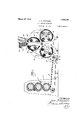
- Fig. 1 is an elevation, with parts in section, of one preferred embodiment of my invention.
- Fig. 2 is a plan view of the tube-forming portion of this embodiment.
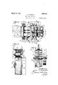
- Fig. 3 is an elevation of parts of the tubeforming apparatus at a pressing and coating station, from the right of Fig. 1 or Fig. 2, parts being sectioned and broken away.
- Fig. 4 is an elevation, from the right of Fig. 1 or Fig. 2, of parts of the tube-for1ning apparatus at a folding and seaming station, parts being sectioned and broken away.
- Fig. 5 is a fragmentary section of one of the tube-building drums and the work thereon, showing the manner in which the endless band of stock is folded over and seamed.
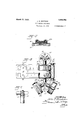
- Fig. 6 is a plan view of parts of another preferred embodiment of my invention.
- Fig. 7 is a fragmentary elevation of the, turret and its mounting shown in Fig. 6.
- the apparatus comprises a calender 10 provided with slit ting knives such as the knife 11 for deliver- 1 ing onto a belt conveyor 12 two continuous strips 13, 13, of sheeted rubber stock.
- a guide and presser roll 14 is journaled between the upper ends of a pair of arms 15, 15, which are pivoted at 16, at their lower ends, upon floor brackets 17, 17, and are urged towardstops 18, 18 on said brackets by pull springs 19, 19, through which they are connected to the respective brackets, the roll thus being so supported as to be peripherally driven, through the stock strips 13, by the conveyor, and to guide the two stock strips 13 as the latter are drawn upward from the delivery end of the conveyor.
- journal standards 20, 20 mounted just beyond the delivery end of the conveyor.
- a pair of journal standards 20, 20 in which is mounted a shaft 21 having journaled thereon at its middle a turret 22.
- a pair of stub shafts, 23, 23, are screwed into and project from opposite sides of the turret.
- Each stub-shaft is formed, from its base toward its outer end, (Fig. 4) with a neck 24, an enlarged journal portion 25, a reduced portion 26 formed at its middle with an open ended, male screw thread 27 of two turns, and with a further 'reduced centering and spring-post portion 28.
- a helical compression spring 29 is mounted upon the reduced portion 28 of the stub shaft, between the screw threaded portion 26 and a flanged bushing 30 slidably mounted upon and projecting beyond the outer end portion of the stub-shaft and retained and controlled as to its position thereon by engagement of its flange with an inwardly extending flange formed on the hub of a tube-building drum 31 which is journaled upon the bushing and upon the journal portion 25 of the stubshaft.
- the hub of the drum is formed with an internal screw thread 32 adapted to coac-t with the thread 27 of the stub-shaft to move 100 dad spring to move the drum axially in the other direction when the drum is .revcrscly rota ed.
- The-screw threads are adapted to p out of mesh with each other and thus periuir further rotation. of the drui'n without substantial aerial movement when it closely approaches the turret.
- annular retainiiuz; plate 83 mounted upon the neclr of the stub-shaft and secured to the hub of the drum by screw bolts, is adapteitl to abut the journal portion of the stub-shatt to st p the reverse axial mov unent of the drun'i wi h the screw threads still meshed.
- an arm 3 1 projecting toward'the guide and PlLHmQl' roll 1d; and formed on its inner face with a stop or socket 35 adapted to engage one after another of the projecting bushings off the drijun assemblies the turret revolves; stop thet-urret with one after another (ii each setot drums 31 hearing against stoclr strip 13 upon the guide and roll 1 1, with the latter forced av stops 18, the drum thus sust' ini of the pull springs 19 to st ct the preroil? the stock against the drum by the roll.
- friction drive including a drive roiler 86 hearing :trictionally against and adapted to slip upon the periphery oi the turret 22 is provided for urging the latter to rotate, ClOCl-YVlSU as viewed in Fig. 1 to bring successive pairs o't druns into coaction with the roll 14:.
- the latter driven by the couveyor 12, is adapted to drive the drum on. the lat-tows own axis While guiding and pressing the stock strip 13 thereonto, and thus, through the action of the screw threads 27., 32, to cause a slow axial movement (it the drum toward the turret, such as to give the winding of.
- tank 39 is mounted upon the stand-- ard: 0,220, and provided with drip coclrs 10 O, adiu'ited to supply coating material to the rolls 58. The latter are oi? such length and are so positioned as to leave ui'icoated a margin 13" ot the work while coating the rest oi? s outer surface.
- Each oi the drums 31 is preferably pro-- ,eoavee vided with.
- a vulcanized rubber band 11 on its stock-receiving surface the band being anchored to the drum along its middle portion and unattached along its margins, and
- the calender being operated to deliver the strips 13, the 'triction drive roller 36 and the coating rolls 68 being cimtinuously driven, and the turret being stopped with one pair of the drums held in. cooperative relation to the guide an d presser roll 1%: by engagement ot the pro jccting bushing .30 with the stop the drums of the pair being in their positions farthest from the turret, the leading end oi? each stock strip 13 is passed about the roll 1+1; while the latter is held away from the drums by hand, and is started upon the drum, at tluxposition shown by broken lines in Fig. 1.
- the two drums imn'lediatcly begin to be driven on their own axes by the guide and presser roll Hand the adjacent coating roll 38 respectively, the action being the same as to the two of drums on opposite sides of the turret, and while the Winding as described is being repeated upon the newly arrived mum at stoclereceiving positionthe windiiuie; oi? slocli' upon the first drum, now at the top
- the springs 19 are then allowed- I?
- a solution of such material in a volatile solvent such as a solution of stearic acid in alcohol, preferably being used.
- the first drum with its coated winding of stock thereon is stopped at the folding position, which is the position of the drum farthest to the right in Fig. 1, and there the margins of the winding are folded over to its middle zone and there joined in interlitt-ed relation, so that the seams of the respective plies are mismatched, as shown clearly in Fig. 5.
- valve-stem patch 43 is applied to one margin of the winding with an overhang therefrom, as shown in Figs. 1, 2 and 3, and the valve stem hole 4.4: (Fig. 3) is punched through the patch and the underlying winding, the patch then being in position to bridge the seam when the margins of the winding are brought together and joined as described.
- the valve stem may be put into the tube, 13, for subsequent mounting in the valve stem hole thereof, by laying itupon the winding so that it will be enclosed when the margins of the latter are folded over and joined.
- the tube is then removed from the drum for vulcanization before the tripping of the bushing 30 of the preceding drum from the stop 35 permits the next indexing of the turret.
- the guide and presser roll 14 of the embodiment above described is omitted and the tube building drums, 46, 46, are journaled with limited axial play upon the arms of spider turrets 47, 47, which are journaled upon vertical axes upon respective standards a8, 48, at opposite sides of the delivery end of the conveyor 12, the drums thus being adapted to be brought in successive sion into a slightly oblique stock-receiving position upon the conveyor 12 so as to be driven thereby and to pick up therefrom as helical windings tube-forming lengths of stock 49 carried by the conveyor from the calender.
- the said lengths are preferably caused to be spaced apart longitudinally upon the conveyor, as by cutting out sections of the continuous strips as indicated by the To cause the turret to rise and fall as it is rotated, so as to lower the adjacent drum onto the conveyor at the end of each indexing movement and lift it therefrom at the beginning of each indexing movement, and to hold it with the drum in proper oblique position to effect the helical winding of the tube blank thereon, the turret is slidably journaled upon the standard and is provided with a hub cam 51 adapted to coact with rollers 52, 52 journaled on the standard.
- a coating roller 38 which may be provided with supporting and fluid-supplying means such as are shown in the embodiment illustrated in Figs. 1 to 5, is provided.
- Apparatus for making inner tubes for tires comprising a substantially cylindrical form of a diameter such as to receive as a winding thereon a strip of tube-forming stock to be formed as an inner tube by the joining of its margins in a longitudinal seam, a support for the strip of stock, the said support having an upwardly facing surface of such extent as at the same time to support in pread condition thereon, against gravity, substantially the entire strip, and means for efiecting such relative movement of the support and the form as to cause the strip to be wound upon the form by relative running of the form upon the support.
- strip-supporting means comprises an endless belt conveyor for the strip.
- Apparatus as defined in claim 1 including a plurality of the forms and a turret constituting a mounting for the several forms.
- Apparatus for making inner tubes for tires comprising a turret, a set of substantially cylindrical winding forms mounted on said turret and each of a diameter such as to receive as a winding thereon a strip of tube-forming stock to be which the meansfor Winding the strips onto 10 formed asan inner tube by the joining of the forms comprises a member adapted to its margins: in a longitudinal. seem, means support the strip in longitudinally spread for winding such strips of stool: onto the condition and relatively to run upon the 5 forms at one part of the turrets orbit, and form to give off the strip thereto.
Landscapes
- Engineering & Computer Science (AREA)
- Mechanical Engineering (AREA)
- Tyre Moulding (AREA)
Description
March 27, 1928.
J. O. GOODWIN TUBE MAKING APPARATUS File'd Auz. 21, 1925 3 Sheets-Sheet! .JnL/ETYZbH J afin [7 5000 12/71? Mmh 27, 1928. 1,663,756
J. O. GOODWIN TUBE MAK I NG APPARATUS Filed Aug. 21. 1925 3 Sheets-Sheet 2 March 27, 1928. 1,663,756
J. o. GOODWIN I TUBE MAKING APPARATUS Filed Aug. 21, 1925 3 Sheets-Sheet 3 JUL/2777272? Jbhn Z7-500dwm Patented Mar. 27, 1928.
UNITED STATES PATENT OFFICE.
JOHN O. GOODWIN, OF AKRON, OHIO, ASSIGNOR TO THE B. F. GOODRICH COMPANY, 01' NEW YORK, N. Y., A CORPORATION OF NEW YORK.
TUBE-MAKING APPARATUS.
Application filed August 21, 1925.
This invention relates to the art of manufacturing tubes such as inner tubes for tires.
It heretofore has been proposed to make such tubes by feeding a strip of sheeted rubber stock froma calender onto a drum, the drum being so rotated and the stock so guided thereonto as to produce a lateral offset of successive plies, and bending over and joining in interfitted relation the stepped margins of the laminated endless band thus produced, to obtain an endless, longitudinally seamed tube.
My general object is to provide improved apparatus for rapidly and economically producing endless, longitudinally seamed tubes. More specific objects are to provide tubeforming apparatus adapted to receive the stock continuously from the calender and to be operated with a comparatively small amount of hand labor; to provide tubeforming apparatus adapted to provide for convenient performance of successive operations upon the stock at different stations; and to provide for the concurrent manipulation at closely adjacent positions of a plurality of stock strips led from the same calender, so as to utilize a comparatively large part of the capacity of the calender.
Of the accompanying drawings:
Fig. 1 is an elevation, with parts in section, of one preferred embodiment of my invention.
Fig. 2 is a plan view of the tube-forming portion of this embodiment.
Fig. 3 is an elevation of parts of the tubeforming apparatus at a pressing and coating station, from the right of Fig. 1 or Fig. 2, parts being sectioned and broken away.
Fig. 4 is an elevation, from the right of Fig. 1 or Fig. 2, of parts of the tube-for1ning apparatus at a folding and seaming station, parts being sectioned and broken away.
Fig. 5 is a fragmentary section of one of the tube-building drums and the work thereon, showing the manner in which the endless band of stock is folded over and seamed.
Fig. 6 is a plan view of parts of another preferred embodiment of my invention.
Serial No. 51,580.
Fig. 7 is a fragmentary elevation of the, turret and its mounting shown in Fig. 6.
Referring first to the embodiment shown in Figs. 1 to 5 of the drawings, the apparatus comprises a calender 10 provided with slit ting knives such as the knife 11 for deliver- 1 ing onto a belt conveyor 12 two continuous strips 13, 13, of sheeted rubber stock. At the delivery end of the conveyor a guide and presser roll 14 is journaled between the upper ends of a pair of arms 15, 15, which are pivoted at 16, at their lower ends, upon floor brackets 17, 17, and are urged towardstops 18, 18 on said brackets by pull springs 19, 19, through which they are connected to the respective brackets, the roll thus being so supported as to be peripherally driven, through the stock strips 13, by the conveyor, and to guide the two stock strips 13 as the latter are drawn upward from the delivery end of the conveyor.
Mounted just beyond the delivery end of the conveyor are a pair of journal standards 20, 20, in which is mounted a shaft 21 having journaled thereon at its middle a turret 22. At each of three positions equally spaced about the axis of the turret a pair of stub shafts, 23, 23, are screwed into and project from opposite sides of the turret. Each stub-shaft is formed, from its base toward its outer end, (Fig. 4) with a neck 24, an enlarged journal portion 25, a reduced portion 26 formed at its middle with an open ended, male screw thread 27 of two turns, and with a further 'reduced centering and spring-post portion 28. A helical compression spring 29 is mounted upon the reduced portion 28 of the stub shaft, between the screw threaded portion 26 and a flanged bushing 30 slidably mounted upon and projecting beyond the outer end portion of the stub-shaft and retained and controlled as to its position thereon by engagement of its flange with an inwardly extending flange formed on the hub of a tube-building drum 31 which is journaled upon the bushing and upon the journal portion 25 of the stubshaft. The hub of the drum is formed with an internal screw thread 32 adapted to coac-t with the thread 27 of the stub-shaft to move 100 dad spring to move the drum axially in the other direction when the drum is .revcrscly rota ed. The-screw threads are adapted to p out of mesh with each other and thus periuir further rotation. of the drui'n without substantial aerial movement when it closely approaches the turret. [in annular retainiiuz; plate 83, mounted upon the neclr of the stub-shaft and secured to the hub of the drum by screw bolts, is adapteitl to abut the journal portion of the stub-shatt to st p the reverse axial mov unent of the drun'i wi h the screw threads still meshed.
Formed upon the standard 20 is an arm 3 1 projecting toward'the guide and PlLHmQl' roll 1d; and formed on its inner face with a stop or socket 35 adapted to engage one after another of the projecting bushings off the drijun assemblies the turret revolves; stop thet-urret with one after another (ii each setot drums 31 hearing against stoclr strip 13 upon the guide and roll 1 1, with the latter forced av stops 18, the drum thus sust' ini of the pull springs 19 to st ct the preroil? the stock against the drum by the roll.
it, friction drive including a drive roiler 86 hearing :trictionally against and adapted to slip upon the periphery oi the turret 22 is provided for urging the latter to rotate, ClOCl-YVlSU as viewed in Fig. 1 to bring successive pairs o't druns into coaction with the roll 14:. The latter, driven by the couveyor 12, is adapted to drive the drum on. the lat-tows own axis While guiding and pressing the stock strip 13 thereonto, and thus, through the action of the screw threads 27., 32, to cause a slow axial movement (it the drum toward the turret, such as to give the winding of. stock upon the drum a helical form, and at the proper time to cause disengagement of the bushing 30 tron the stop and thus permit rotation of the turret by the :rt'riction. drive roller 35 to bring the next druin into stock receiving position.
l ournaled in spring backed journal blocks 8?, 3T. slidably mounted in the tops of the standards 20, 20, is a pair of driven coating rolls 8, 38, adapted to bear upon the worlr as succes Jo pairs of drums 22 with the windings or wrappings ot the strips 13 thereon are broug it to the top of the turrets orbit. 1i, tank 39 is mounted upon the stand-- ard: 0,220, and provided with drip coclrs 10 O, adiu'ited to supply coating material to the rolls 58. The latter are oi? such length and are so positioned as to leave ui'icoated a margin 13" ot the work while coating the rest oi? s outer surface.
Each oi the drums 31 is preferably pro-- ,eoavee vided with. a vulcanized rubber band 11 on its stock-receiving surface, the band being anchored to the drum along its middle portion and unattached along its margins, and
thus adapted to serve as a liner for the tacky.
rubber steel; in the winding oi? the latter on the drui'u and the folding over of the margins of the rubber Winding to tube form.
in the beginning of the operation of this embodiment of my invention, the calender being operated to deliver the strips 13, the 'triction drive roller 36 and the coating rolls 68 being cimtinuously driven, and the turret being stopped with one pair of the drums held in. cooperative relation to the guide an d presser roll 1%: by engagement ot the pro jccting bushing .30 with the stop the drums of the pair being in their positions farthest from the turret, the leading end oi? each stock strip 13 is passed about the roll 1+1; while the latter is held away from the drums by hand, and is started upon the drum, at tluxposition shown by broken lines in Fig. 1. to pull the roll 14 against the drums, which are thereupon driven by said roll, the latter being driven by the conveyor 12, and the strips 13 are thuswound upon the respective drums, the screw threads 27, 32, functioning to move the drums axially toward the turret as they are rotated, so that the. stock strip. is wound helically upon each drum, providing a lateral offset of successive plies, as is shown clearly in Fig. 3.
[it the end of approximately two revolutions of the drum the bushing 30 engaged with the stop has been moved tmvardthe turret, by the axial movement of the drum, r-auiiiciently to clear it from the stop 35., whereupon the friction drive roller 36 becomes etlective to rotate the turret to step the turret forward one-third oi? a revolution, the bushing 30 of the next drum stopping this movement by abutting the stop 35 and causing the drive roller 36 to slip.
This partial revolution of the turret causes each strip 13 to start to wind upon the set of drums as a group and thus to extend tangen tially from one drum to the next, as shown in Fig. 1,. and as the turret stops with the second drum in stock-receiving position and the first drum at the coating; position, an operator sevcrs the strip at 12, Fig. 1, and by hand applies the severed end portions to the respective (lI11]'.l'1S,; as indicated by the broken lines in Fig; 1.
The two drums imn'lediatcly begin to be driven on their own axes by the guide and presser roll Hand the adjacent coating roll 38 respectively, the action being the same as to the two of drums on opposite sides of the turret, and while the Winding as described is being repeated upon the newly arrived mum at stoclereceiving positionthe windiiuie; oi? slocli' upon the first drum, now at the top The springs 19 are then allowed- I? of the 'turrets orbit, is compacted by the coating roll 38 and provided on its outer face except along the margin 13 with a coating of adhesion-preventing material from the tank 39, a solution of such material in a volatile solvent, such as a solution of stearic acid in alcohol, preferably being used.
At the next indexing of the turret the first drum with its coated winding of stock thereon is stopped at the folding position, which is the position of the drum farthest to the right in Fig. 1, and there the margins of the winding are folded over to its middle zone and there joined in interlitt-ed relation, so that the seams of the respective plies are mismatched, as shown clearly in Fig. 5.
Preferably before each winding reaches the coating position a valve-stem patch 43 is applied to one margin of the winding with an overhang therefrom, as shown in Figs. 1, 2 and 3, and the valve stem hole 4.4: (Fig. 3) is punched through the patch and the underlying winding, the patch then being in position to bridge the seam when the margins of the winding are brought together and joined as described. The valve stem may be put into the tube, 13, for subsequent mounting in the valve stem hole thereof, by laying itupon the winding so that it will be enclosed when the margins of the latter are folded over and joined.
The seam. of the tube is rolled with a hand roller 45 (Fig. i), the drum being rotated by hand to facilitate this operation, and being finally so turned that the retaining plate 33 abuts the journal portion 25 of the stubshaft.
The tube is then removed from the drum for vulcanization before the tripping of the bushing 30 of the preceding drum from the stop 35 permits the next indexing of the turret.
Thus the operation is continued to produce successive tubes from the continuously delivered calendered strips 13.
In the embodiment of my invention shown in Fig. 6 the guide and presser roll 14 of the embodiment above described is omitted and the tube building drums, 46, 46, are journaled with limited axial play upon the arms of spider turrets 47, 47, which are journaled upon vertical axes upon respective standards a8, 48, at opposite sides of the delivery end of the conveyor 12, the drums thus being adapted to be brought in succes sion into a slightly oblique stock-receiving position upon the conveyor 12 so as to be driven thereby and to pick up therefrom as helical windings tube-forming lengths of stock 49 carried by the conveyor from the calender. The said lengths are preferably caused to be spaced apart longitudinally upon the conveyor, as by cutting out sections of the continuous strips as indicated by the To cause the turret to rise and fall as it is rotated, so as to lower the adjacent drum onto the conveyor at the end of each indexing movement and lift it therefrom at the beginning of each indexing movement, and to hold it with the drum in proper oblique position to effect the helical winding of the tube blank thereon, the turret is slidably journaled upon the standard and is provided with a hub cam 51 adapted to coact with rollers 52, 52 journaled on the standard.
A coating roller 38, which may be provided with supporting and fluid-supplying means such as are shown in the embodiment illustrated in Figs. 1 to 5, is provided.
The operation of this embodiment is the same as that above described with relation to the embodiment of Figs. 1 to 5, as to the manipulation of the windings of stock, and in all other respects will be obvious from the foregoing description of the structure.
Both embodiments provide the advantages set out in the above statement of objects.
Further modifications may be employed within the scope of my invention. and I do not wholly limit my claims to the embodiments here shown.
I claim:
1. Apparatus for making inner tubes for tires, the said apparatus comprising a substantially cylindrical form of a diameter such as to receive as a winding thereon a strip of tube-forming stock to be formed as an inner tube by the joining of its margins in a longitudinal seam, a support for the strip of stock, the said support having an upwardly facing surface of such extent as at the same time to support in pread condition thereon, against gravity, substantially the entire strip, and means for efiecting such relative movement of the support and the form as to cause the strip to be wound upon the form by relative running of the form upon the support.
2. Apparatus as defined in claim 1 in which the form is mounted in oblique relation to the stock-engaging surface of the support.
3. Apparatus as defined in claim 1 in which the strip-supporting means comprises an endless belt conveyor for the strip.
1. Apparatus as defined in claim 1 including a plurality of the forms and a turret constituting a mounting for the several forms.
5. Apparatus for making inner tubes for tires, the said apparatus comprising a turret, a set of substantially cylindrical winding forms mounted on said turret and each of a diameter such as to receive as a winding thereon a strip of tube-forming stock to be which the meansfor Winding the strips onto 10 formed asan inner tube by the joining of the forms comprises a member adapted to its margins: in a longitudinal. seem, means support the strip in longitudinally spread for winding such strips of stool: onto the condition and relatively to run upon the 5 forms at one part of the turrets orbit, and form to give off the strip thereto.
means for applying an adhesion-preventing In Witness whereof I have hereunto set 15 materialto the stripe at another part of the my hand this 18th day of August, 1925. turrets orbit. 4
6. Apparatus as defined in claim 5 in JOHN UG-OODVVIN.
Publications (1)
| Publication Number | Publication Date |
|---|---|
| US1663756A true US1663756A (en) | 1928-03-27 |
Family
ID=3414757
Family Applications (1)
| Application Number | Title | Priority Date | Filing Date |
|---|---|---|---|
| US1663756D Expired - Lifetime US1663756A (en) | Tube-making appabattjs |
Country Status (1)
| Country | Link |
|---|---|
| US (1) | US1663756A (en) |
-
0
- US US1663756D patent/US1663756A/en not_active Expired - Lifetime
Similar Documents
| Publication | Publication Date | Title |
|---|---|---|
| US3068133A (en) | Method of and apparatus for manufacturing a reinforced plastic product | |
| EP0246497A2 (en) | Method for manufacturing a first stage radial tire for vehicles | |
| DE2653022A1 (en) | METHOD OF MANUFACTURING A TIRE FOR AIR TIRES | |
| US2343747A (en) | Machine for making tubular structures | |
| US4783230A (en) | Manufacture of ply fabric for reinforced rubber articles | |
| DE4226199A1 (en) | Automatic mfr. of bead assembly for tyres - comprises carrying bead core on drum on carousel opposite units for winding, folding and bonding filler and reinforcing strips by inflating heated bags | |
| US3057566A (en) | Tire bead building machine | |
| US2268125A (en) | Coiler | |
| US2149851A (en) | Apparatus for handling coiled wire and rod | |
| US1663756A (en) | Tube-making appabattjs | |
| US20080087367A1 (en) | Method And Apparatus For Manufacturing Tyres For Vehicle Wheels | |
| US1665585A (en) | Method and apparatus for making laminated annular articles | |
| US1498532A (en) | Method and apparatus eos covering and rolling tire bead cores | |
| US2442946A (en) | Apparatus for producing sheet material | |
| US1317426A (en) | Method of hakckia- sheet-si ocs | |
| US2874916A (en) | Coil holder | |
| DE102017223328B4 (en) | Tire element extraction device and tire element extraction method | |
| US2377950A (en) | Manufacture of spiral wound members | |
| US3530901A (en) | Reinforced hollow plastic pipe | |
| US3188254A (en) | Method and apparatus for making endless belt bodies | |
| GB2179307A (en) | Method and apparatus for pneumatic tyre manufacture | |
| US2392194A (en) | Apparatus for forming tubing | |
| KR20060116007A (en) | Process and apparatus for producing semifinished products for the manufacture of tires for vehicle wheels | |
| US2693779A (en) | Machine for making round flexible metal tubes | |
| US3055278A (en) | Reinforced plastic pipe |