US1663754A - Tube and method of making same - Google Patents
Tube and method of making same Download PDFInfo
- Publication number
- US1663754A US1663754A US1663754DA US1663754A US 1663754 A US1663754 A US 1663754A US 1663754D A US1663754D A US 1663754DA US 1663754 A US1663754 A US 1663754A
- Authority
- US
- United States
- Prior art keywords
- tube
- drum
- margins
- rubber
- plies
- Prior art date
- Legal status (The legal status is an assumption and is not a legal conclusion. Google has not performed a legal analysis and makes no representation as to the accuracy of the status listed.)
- Expired - Lifetime
Links
- 238000004519 manufacturing process Methods 0.000 title description 5
- 229920001971 elastomer Polymers 0.000 description 9
- 238000004804 winding Methods 0.000 description 8
- 238000000034 method Methods 0.000 description 4
- 238000003490 calendering Methods 0.000 description 3
- 239000012530 fluid Substances 0.000 description 3
- 238000005304 joining Methods 0.000 description 3
- 239000000463 material Substances 0.000 description 3
- 239000002904 solvent Substances 0.000 description 2
- 241000870659 Crassula perfoliata var. minor Species 0.000 description 1
- LFQSCWFLJHTTHZ-UHFFFAOYSA-N Ethanol Chemical compound CCO LFQSCWFLJHTTHZ-UHFFFAOYSA-N 0.000 description 1
- 239000002253 acid Substances 0.000 description 1
- 239000000853 adhesive Substances 0.000 description 1
- 230000001070 adhesive effect Effects 0.000 description 1
- 230000003467 diminishing effect Effects 0.000 description 1
- 239000007788 liquid Substances 0.000 description 1
- 238000012986 modification Methods 0.000 description 1
- 230000004048 modification Effects 0.000 description 1
- 238000005096 rolling process Methods 0.000 description 1
- 229920006395 saturated elastomer Polymers 0.000 description 1
- 238000003860 storage Methods 0.000 description 1
- 239000000126 substance Substances 0.000 description 1
- 239000004636 vulcanized rubber Substances 0.000 description 1
Images
Classifications
-
- B—PERFORMING OPERATIONS; TRANSPORTING
- B29—WORKING OF PLASTICS; WORKING OF SUBSTANCES IN A PLASTIC STATE IN GENERAL
- B29D—PRODUCING PARTICULAR ARTICLES FROM PLASTICS OR FROM SUBSTANCES IN A PLASTIC STATE
- B29D23/00—Producing tubular articles
- B29D23/24—Endless tubes, e.g. inner tubes for pneumatic tyres
-
- B—PERFORMING OPERATIONS; TRANSPORTING
- B29—WORKING OF PLASTICS; WORKING OF SUBSTANCES IN A PLASTIC STATE IN GENERAL
- B29K—INDEXING SCHEME ASSOCIATED WITH SUBCLASSES B29B, B29C OR B29D, RELATING TO MOULDING MATERIALS OR TO MATERIALS FOR MOULDS, REINFORCEMENTS, FILLERS OR PREFORMED PARTS, e.g. INSERTS
- B29K2021/00—Use of unspecified rubbers as moulding material
Definitions
- This invention relates to the tube-making art. and especially to the manufacture ol: annular rubber tubes such as inner tubes for tires.
- a more specific object is to provide improved procedure and apparatus for forming tubes from freshly calendered stock, which may be taken directly from the calender, and thus to avoid the expense ot' storage and of the employment of equipment such as liners t'or storing and handling the calendered stock.
- a further object is the provision ot' an improved seam in a longitudinally seamed. laminated tube.
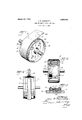
- Fig. 1 is a perspective vieu' ot' a tubebuilding drum embodying and adapted to carry out my invention, with the work in place thereon.
- Fig. 2 is a side elevation ot the same, at a later stage of operation, parts being sectioned and broken away.
- Fig. 3 is a section ot a part oi the drum and the Wort thereon at a later stage.
- Fig. si is a side elevation otI the same at a still later stage of operation.
- the apparatus comprises a drum 10 adapted to be mounted for rotation and having upon its outer face an annular band 11 of flexible, elastic, nonadhesive materialsuch as vulcanized rubber, this band prefe ably being 'formed with a middle rib 12 on its inner face, set into a groove on the surface of the drum, so as to maintain the band properly centered upon the drum.
- a strip 13 of calendered stock is drawn 'from a source of supply such as a calender and Wound upon the drum l() over the band 1l.
- a source of supply such as a calender and Wound upon the drum l() over the band 1l.
- the Winding being given such helical form that the margins of each turn or' the material are slightly oli-set from those of the preceding turn, as will be understood upon reference to Figs. 1 and 2.
- the successive convolutions may be progressively compacted against each other by any suitable rolling means during the winding operation and When the stock is drawn directly from the calender the warm and tacky condition of the rubber results in strong adhesion of the plies.
- the strip 13 is severed, as upon the line 14 ot Fig. l, preferably at the same position circumferentiallv ot vthe drinn as that ot the leading end 1:3"- ol.' the winding, and the-residue 13b ot' the stock strip is -freed from the drum assembly.
- a valve stem patch 15 is then mounted upon the margin of the winding at Which the last wound ply overhangs the underlying plies. as shown in Figs. 1 and 2, and the valve stem hole 15L is punched in the patch and through the underlying tube stock.
- the exposed outer surface ot' the Winding, except the margin 1T (Fig. 2) opposite that to which the valve stem pad is attached, is treated with a wash consisting of a highly volatile liquid containing a suitable'substance in solution or suspensionto prevent adhesion oi the rubber when the solvent evaporates, which occurs quickly because of the warm condition of the stock when it is drawn direct-ly from the calender.
- a suitable wash for this purpose is a solution, which may be super-saturated, of stearie acid in alcohol. The Wash readily may be applied by means oit a paint brush 18, Fig. 2, held against the Work While the drum is rotated.
- the margin 16 upon which the valve stem patch is mounted is progressively turned over to approximately the middle line ot' the assembly, together with the adjacent margin of the non-adhesive underlying band 11, which may be readily accomplished by rotating the drum and manipulating the said margins with a suitable turning tool, as will be readily understood by those skilled in the art.
- the tube is then removed from the drum,
- seam and valve stem patch are on its inner periphery, and is vulcanized under internal fluid pressure such as to prevent contact and adhesion of its inner surfaces, and preferably in a mold, a valve stem preferably being inserted prior to the vuleanization.
- the method results in an improved longitudinally seamed tube of which the cams of the several plies are mis-matched, and having the same number of plies at all parts of the tube.
- the employment of the flexible band ll permits the tacky rubber plies to be turned over and joined Without the einployment of other precaution. against undesired adhesion thereof.
- the method of makingl an annular tube which comprises helically Winding in a plurality of plies a continuous strip of tuheforming mnterlial to provide an annular structure with stepped margins, and joining said margins to each other in interfitted relation.
- a rubber tube which comprises forming a strip of unvul- Lenawee oanized rubber with longitudinal margins of diminishing; thickness toward the edges of the strip, folding said margins over onto said intermediate Zone and there joining them together, and vulcanizing the resultingr tubular structure While holding it dis tended against an enclosing mold by internal fluid pressure.
- a tube comprisingT laterally offset layers of sheet material, the margins of each layer being joined in a longitudinal butt seam, the seams of the layers beine' mis-matched, and a plurality of the layers comprising a continuous winding of material common to the said layers.
Landscapes
- Engineering & Computer Science (AREA)
- Mechanical Engineering (AREA)
- Tyre Moulding (AREA)
- Lining Or Joining Of Plastics Or The Like (AREA)
Description
March 27, 1928. 1,663,754
J. R. GAMMETER TUBE AND METHOD OF MAKING SAME Filed Aug. 3, 1925 Patented Mar. 27, 1928.
UNITED STATES 1,6t`13,75=tY PATENT OFFICE.
JOHN R. GAMMETER, OF AKRON, OHO. ASSIGNOR TO THE B. F. GOODRICH COMPANY, OF NEW YORK, N. Y., A CORPORATION OF NEW YORK.
TUBE AND METHOD 0F MAKING SAME.
Application ed August 3, 1925. Serial No. 47,690.
This invention relates to the tube-making art. and especially to the manufacture ol: annular rubber tubes such as inner tubes for tires.
Its chiet' objects are economy ot time and labor and improved adhesion of the plies ot a laminated tube. A more specific object is to provide improved procedure and apparatus for forming tubes from freshly calendered stock, which may be taken directly from the calender, and thus to avoid the expense ot' storage and of the employment of equipment such as liners t'or storing and handling the calendered stock. A further object is the provision ot' an improved seam in a longitudinally seamed. laminated tube.
Of the accompanying drawings:
Fig. 1 is a perspective vieu' ot' a tubebuilding drum embodying and adapted to carry out my invention, with the work in place thereon.
Fig. 2 is a side elevation ot the same, at a later stage of operation, parts being sectioned and broken away.
Fig. 3 is a section ot a part oi the drum and the Wort thereon at a later stage.
Fig. si is a side elevation otI the same at a still later stage of operation.
Referring to the drawings, the apparatus comprises a drum 10 adapted to be mounted for rotation and having upon its outer face an annular band 11 of flexible, elastic, nonadhesive materialsuch as vulcanized rubber, this band prefe ably being 'formed with a middle rib 12 on its inner face, set into a groove on the surface of the drum, so as to maintain the band properly centered upon the drum.
In the practice of my method in its preferred form, a strip 13 of calendered stock is drawn 'from a source of supply such as a calender and Wound upon the drum l() over the band 1l. the Winding being given such helical form that the margins of each turn or' the material are slightly oli-set from those of the preceding turn, as will be understood upon reference to Figs. 1 and 2.
The successive convolutions may be progressively compacted against each other by any suitable rolling means during the winding operation and When the stock is drawn directly from the calender the warm and tacky condition of the rubber results in strong adhesion of the plies.
When the desired number of plies have thus been drawn onto the drum, the strip 13 is severed, as upon the line 14 ot Fig. l, preferably at the same position circumferentiallv ot vthe drinn as that ot the leading end 1:3"- ol.' the winding, and the-residue 13b ot' the stock strip is -freed from the drum assembly. i
A valve stem patch 15 is then mounted upon the margin of the winding at Which the last wound ply overhangs the underlying plies. as shown in Figs. 1 and 2, and the valve stem hole 15L is punched in the patch and through the underlying tube stock. The exposed outer surface ot' the Winding, except the margin 1T (Fig. 2) opposite that to which the valve stem pad is attached, is treated with a wash consisting of a highly volatile liquid containing a suitable'substance in solution or suspensionto prevent adhesion oi the rubber when the solvent evaporates, which occurs quickly because of the warm condition of the stock when it is drawn direct-ly from the calender. A suitable wash for this purpose is a solution, which may be super-saturated, of stearie acid in alcohol. The Wash readily may be applied by means oit a paint brush 18, Fig. 2, held against the Work While the drum is rotated.
After the solvent has evaporated, the margin 16, upon which the valve stem patch is mounted, is progressively turned over to approximately the middle line ot' the assembly, together with the adjacent margin of the non-adhesive underlying band 11, which may be readily accomplished by rotating the drum and manipulating the said margins with a suitable turning tool, as will be readily understood by those skilled in the art.
The opposite margins of the band 11 and of the Work are then similarly turned over and the margins of the Winding ofthe tacky rubber strip 13 are progressively joined together in the mis-matched intcrtitted relation which is clearly shown in Fig. 3. The portion of the valve stem patch 15 which projects 'from the margin 16 contacts and is stuck to the inner face of the inner ply of the margin 17, so that it lies Within the resulting tube, bridging the seam. The seam is then compacted by rotating the drum with the work thereon while holding ay roller 19 (Fig. l) against the middlel portion of the Work.
The tube is then removed from the drum,
turned so that the seam and valve stem patch are on its inner periphery, and is vulcanized under internal fluid pressure such as to prevent contact and adhesion of its inner surfaces, and preferably in a mold, a valve stem preferably being inserted prior to the vuleanization.
The method results in an improved longitudinally seamed tube of which the cams of the several plies are mis-matched, and having the same number of plies at all parts of the tube. The employment of the flexible band ll permits the tacky rubber plies to be turned over and joined Without the einployment of other precaution. against undesired adhesion thereof.
Modifications may be employed Within the scope of my invention and l do not Wholly limit my claims to the specific description herein given by Way of illustration.
I claim:
l. The method of makingl an annular tube which comprises helically Winding in a plurality of plies a continuous strip of tuheforming mnterlial to provide an annular structure with stepped margins, and joining said margins to each other in interfitted relation.
2. The method of making, a rubber tube which comprises forming a strip of unvul- Lenawee oanized rubber with longitudinal margins of diminishing; thickness toward the edges of the strip, folding said margins over onto said intermediate Zone and there joining them together, and vulcanizing the resultingr tubular structure While holding it dis tended against an enclosing mold by internal fluid pressure.
3. The method of making an annular rubber tube which comprises windingf a plurality of layers of tacky rubber stock onto a forni with one layer offset from another, to provide stepped margins, folding' the stepped margins onto said intermediate portion and joining them together in interiitted relation, with the tvvo edgefaces of each ply substantially abutting each other, and vuleanizing the resulting tube vin a mold under internal fluid pressure.
4c. A tube comprisingT laterally offset layers of sheet material, the margins of each layer being joined in a longitudinal butt seam, the seams of the layers beine' mis-matched, and a plurality of the layers comprising a continuous winding of material common to the said layers.
ln witness whereof I have hereunto set my hand this 25th day of July, 1925.
JOHN R. GAMMETER.
Publications (1)
| Publication Number | Publication Date |
|---|---|
| US1663754A true US1663754A (en) | 1928-03-27 |
Family
ID=3414756
Family Applications (1)
| Application Number | Title | Priority Date | Filing Date |
|---|---|---|---|
| US1663754D Expired - Lifetime US1663754A (en) | Tube and method of making same |
Country Status (1)
| Country | Link |
|---|---|
| US (1) | US1663754A (en) |
-
0
- US US1663754D patent/US1663754A/en not_active Expired - Lifetime
Similar Documents
| Publication | Publication Date | Title |
|---|---|---|
| US1746701A (en) | Flexible conduit and method of making the same | |
| US3143156A (en) | Tire repair | |
| US1797193A (en) | Method of making flexible conduits | |
| US2287282A (en) | Method of making flat articles having grooved surfaces | |
| US2623571A (en) | Method of splicing tubular articles | |
| US1478083A (en) | Wire-wound hose | |
| US2244557A (en) | Method of producing tear resisting rubber sheeting | |
| US1663754A (en) | Tube and method of making same | |
| US1970513A (en) | Hose nipple connection | |
| US2592724A (en) | Inner tube for pneumatic tires and method of making | |
| US2372382A (en) | Method of constructing safety inner tubes | |
| US2115543A (en) | Process of covering perforated rolls | |
| US2310642A (en) | Vulcanizing apparatus | |
| US2171764A (en) | Method for making seamless tubing | |
| US2099514A (en) | Puncture-sealing inner tube for pneumatic tires | |
| US1424386A (en) | Process of forming tubes | |
| US2401625A (en) | Method of making puncture sealing material | |
| US1237698A (en) | Self-healing tube and process of making same. | |
| US1068691A (en) | Patch for rubber articles. | |
| US1670445A (en) | Tube-making apparatus | |
| US2524662A (en) | Corrugated tube | |
| US1009752A (en) | Process of manufacturing vehicle-tires. | |
| US1211867A (en) | Tire-patch and the process of making the same. | |
| US1472435A (en) | Inner tube for pneumatic tires and method of making the same | |
| US1403058A (en) | Tire repair material |