US1663644A - Air-circulating device for warm-air furnaces - Google Patents
Air-circulating device for warm-air furnaces Download PDFInfo
- Publication number
- US1663644A US1663644A US245391A US24539128A US1663644A US 1663644 A US1663644 A US 1663644A US 245391 A US245391 A US 245391A US 24539128 A US24539128 A US 24539128A US 1663644 A US1663644 A US 1663644A
- Authority
- US
- United States
- Prior art keywords
- fan
- shutter
- air
- panel
- vanes
- Prior art date
- Legal status (The legal status is an assumption and is not a legal conclusion. Google has not performed a legal analysis and makes no representation as to the accuracy of the status listed.)
- Expired - Lifetime
Links
- 230000005484 gravity Effects 0.000 description 5
- 241000394706 Ploceus capensis Species 0.000 description 3
- 238000010276 construction Methods 0.000 description 3
- 239000002184 metal Substances 0.000 description 2
- 241000370092 Actiniopteris Species 0.000 description 1
- 239000012634 fragment Substances 0.000 description 1
- 210000003141 lower extremity Anatomy 0.000 description 1
- 230000004048 modification Effects 0.000 description 1
- 238000012986 modification Methods 0.000 description 1
- 230000004936 stimulating effect Effects 0.000 description 1
- 210000001364 upper extremity Anatomy 0.000 description 1
Images
Classifications
-
- F—MECHANICAL ENGINEERING; LIGHTING; HEATING; WEAPONS; BLASTING
- F24—HEATING; RANGES; VENTILATING
- F24H—FLUID HEATERS, e.g. WATER OR AIR HEATERS, HAVING HEAT-GENERATING MEANS, e.g. HEAT PUMPS, IN GENERAL
- F24H9/00—Details
- F24H9/0052—Details for air heaters
Definitions
- This invention relates to devices for arti- I ficially stimulating the circulation of air through the air jackets of warm air furnaces and the intake and discharge ducts thereof.
- Various devices of this character have heretofore been, proposed which include an electrically operated fan located'in the return air intake duct or passageway leading into the furnace jacket and a shutter or shutters locatedat one or both sides of V the fan, with various automatic means for closing the shutter or shutters when the fan is operating and opening the shutter or shutters whenthe fan is idle so as to permit, in
- the shutter is'mounted eccentrically ona pivot slightly inclined from the vertical, so that the shutter tends by gravity to 7 swing to open position, and the increased air pressure in the furnace jacket created by the fan is relied on to close the shutter by back pressure thereagainst.
- the principal object of our present invention is to provide a fan and shutter construction operating on a ldiflerent principle nd thus have no closing lied on to close the shutter and hold it closed while the fan is, operating, but the shutter is closed and held closed by a por-f tion of thefan blast directed thereagainst the nature of a deflector which is so shaped and located relatively to the fan and shutter as to continuously fan blast directly against the shutter.
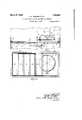
- Fig. 1 is a top plan'view of thefdevice, shown as located in and crosswise of the usual air inflow orreturn conduit to the furnace jacket, with the shutter vanes closed;
- Fig. 2 is a front elevation of the device, also showing the shutter vanes closed;
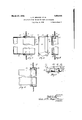
- Fig. 3 is an enlarged vertical section broken out through the frame and the deflector, taken on the line 3-3 ofFig. 1
- Fig. 43 is a perspective elevation of the deflector, viewed in the direction of the ar-' rowtof Fig.1;
- Fig. 5 is an enlarged vertical section broken out taken on the line -55 of Fig. 1;
- Fig. 6 is a view similar to Fig. 5 but showing the shutter vane in open position; i
- Fig. 7 is a fragmentary topplan view ofa pair'of shutter vanes and'their connecting link, in section through the vane spindles on the line 7-7 ofFig. 2..
- Fig. 1 a fragment of the usual rectangular cold. air, intake conduit which in practice leads into the bottom of the warm air jacket of the furnace. Disposed within and crosswise of this conduit is our improved air circulating unit which, in the preferred form herein illustrated, is constructed as follows. 7
- 11 designates arectangular frame structure which may be secured to the internal walls of the conduit 10 as by angle brackets 12.
- 13 designates a fan supporting panel formed with a central opening l-to accommodate the fan 15 and with forwardly directed flanges 13" (Fig. 3) fitting within the by screws 16.
- the fan frame 17 carrying the electricmotor'18 on the armatureof which the fan 15 is mounted.
- a group of shutter vanes 19 conveniently made of'sheet-metal.
- the metal-forming the-vane is folded; rearwardly on the body portion of the vane,- as shown at 19 in Fig. 7 5 and the free end of the ,folded portion is curled around and secured toa pivot spindle 20 which latter, as best shown in Fig. 5, has upper and lower conicalbearings in strips 21 and 22 secured tothe upper and lower limbs of the frame 11.
- a fixed deflector. element by which a ,portion of the fan blast is intercepted and directed against the adjacent open shutter vane.
- This deflectonin asiinple and practical form capable of being made from asheet-metal blank, is shown in perspective detail in Fig. 4 and comprises a flat plate 26 disposed substantially parallel with the panel 13, upper and lower rearward extensionsQZ and 28 continuous with the upper and lower edges of the plate 26,
- extensions may be attached ,to the frame 11 by the screws 16, and inclined wings 29 and 30 ,continuous with the vertical -margins of the plate 26, the wing “29 being inclined toward the fan 15 to catch a portion of the fan blast, and the wing 30 being inclined toward the shutter vane 19 that lies nearest the fan to direct the intercepted portionof theqblast against said shutter vane.
- the gaps between the extensions 27, 28 and -theside wings 29 and 30 are closed by angle strips 3 1 spot-welded, soldered or otherwise secured thereto, this construction also stiffening said extensions and wings.
- an air circulating device for furthe combination of a panel mounted in the air intake conduit of a furnace, said a fan opening, a fan mounted on said panel, a shutter mounted in said conduit at one side of said fan, said shutter being so mounted as to swing to open position when the fan is idle, and a fixed vertical deflector plate in said conduit in front of said panel, said plate having on one vertical edge thereof a Wing inclined toward said fan and on the other vertical edge thereof a wing inclined toward said shutter.
- An air circulating unit adapted to be mounted in and crosswise of the air intake conduit of a furnace, comprising, in combination, a frame of the internal width and height of said conduit, a fan-supporting panel mounted in said frame, said panel having a fan opening, a'fan and fan motor mounted on said panel, a gravity-opening shutter pivotally mounted in said frame at one side of said panel, and a fixed deflector plate mounted on said frame in front of said panel adapted to intercept a portion of the fan blast and direct it against said shutter to close the latter and hold it closed.
- An air circulating unit adapted to be mounted in and crosswise of the air intake
- conduit of a furnace comprising, in combination, a frame of the internal width and height of said conduit, a fan-supporting panel mounted in said frame, said panel having a fan opening, a fan and fan motor mounted on said panel, a gravity-opening shutter pivotally mounted in said frame at one side of said panel, and a device operative to deflect a portion of the fan blast against said shutter comprising a vertical plate in front of and substantially parallel with said panel, rearward extensions on the top and bottom edges of said plate attached to said frame, a wing on one vertical edge of said plate inclined toward said fan, and a wing on the other vertical edge of said plate inclined toward said shutter.
- vanes mounted in said conduit at one side of said panel, said vanes being mounted on inclined pivots located eccentrically widthwise of the blades whereby the latter swing by gravity to open position, means for deflecting a portion of the fan blast against the vane nearest thefa-n when the latter is in operation, and means connecting said vanes for simultaneous operation.
- An air'circulating unit adapted to bemounted in and crosswise of the air intake conduit of a furnace, comprising, in combination, a frame adapted to be attached to thewalls of said conduit, a fan supporting panel mounted in said frame, said panel having a fan opening, a fan and fan motor mounted on said panel, a group of shutter vanes mounted in said frame at one side of said panel, said vanes being mounted on inclined pivots located eccentrically widthwise of theblades whereby the latter swing by gravity tov open position, 'a fixed deflectormounted on said frame infront of said panel serving to intercept and direct a portion of the fan blast against the vane nearest the fan when the latter is in operation, arms on said vanes, and a. link pivoted to said arms,
Landscapes
- Engineering & Computer Science (AREA)
- Physics & Mathematics (AREA)
- Thermal Sciences (AREA)
- Chemical & Material Sciences (AREA)
- Combustion & Propulsion (AREA)
- Mechanical Engineering (AREA)
- General Engineering & Computer Science (AREA)
- Air-Flow Control Members (AREA)
Description
March 27, 1928. 1,663,644
L. c. WEAVER ET AL AIR CIRCULATING DEVICE FOR WARM AIR FURNACES Filed Jan. 9, 1928 2 Sheets-Sheet 1 A TTORNEYS.
March 27, 1928. 1,663,644
L. c. WEAVER ET AL III/l INVENTORS A TTORNEYS.
Patented Mar. 27, 1928.
LEWIS c. WEAVER, or CHICAGO, AND
CORPORATION OF LOUISIANA.
WALTER H. RIETZ, OF RAVINIA, ILLINOIS. ASSIGNORS TO ILG ELECTRIC VENTILATING COMPANY,
OF CHICAGO, ILLINOIS, A.
AIR-CIRCULATING DEVICE FOR WARM-AIR FURNACES.
Application filed January 9, 1928. Serial No. 245,391.
This invention relates to devices for arti- I ficially stimulating the circulation of air through the air jackets of warm air furnaces and the intake and discharge ducts thereof. Various devices of this character have heretofore been, proposed which include an electrically operated fan located'in the return air intake duct or passageway leading into the furnace jacket and a shutter or shutters locatedat one or both sides of V the fan, with various automatic means for closing the shutter or shutters when the fan is operating and opening the shutter or shutters whenthe fan is idle so as to permit, in
the lattercase, a free and unobstructed natural circulation of the air. In some of these devices the shutter is'mounted eccentrically ona pivot slightly inclined from the vertical, so that the shutter tends by gravity to 7 swing to open position, and the increased air pressure in the furnace jacket created by the fan is relied on to close the shutter by back pressure thereagainst. It has been found in practice, however, that where such units are installed, after the fan is started, it createsa partial vacuum, due to siphonic action, on the sides of the air blast which, so far from closing the shutter, actually 1 tends to keep it open, and the resistance to the .free circulation beyond the qfan sets up a local circulation between the front and the back of the fan through theshutter opening, the back flow of air through the shutter opening impinging open shutter blade a eifect on the latter. v
The principal object of our present invention is to provide a fan and shutter construction operating on a ldiflerent principle nd thus have no closing lied on to close the shutter and hold it closed while the fan is, operating, but the shutter is closed and held closed by a por-f tion of thefan blast directed thereagainst the nature of a deflector which is so shaped and located relatively to the fan and shutter as to continuously fan blast directly against the shutter. Our invention, its mode and principle of operation, and the advantagesinhering therein will be readily understood hypersons skilled lin'the art from the following detailed description, taken in' connection deflect a portion of the only on the edge of the and wherein back pressure of air is not re- 'frame'll and attached thereto as by means of a suitable stationary device in with the accompanying drawings, in which we have illustrated one practical and approved mechanical embodimentwof the invention, and wherein n I Fig. 1 is a top plan'view of thefdevice, shown as located in and crosswise of the usual air inflow orreturn conduit to the furnace jacket, with the shutter vanes closed;
Fig. 2 is a front elevation of the device, also showing the shutter vanes closed;
Fig. 3 is an enlarged vertical section broken out through the frame and the deflector, taken on the line 3-3 ofFig. 1
Fig. 43 is a perspective elevation of the deflector, viewed in the direction of the ar-' rowtof Fig.1;
Fig. 5 is an enlarged vertical section broken out taken on the line -55 of Fig. 1;
Fig. 6 is a view similar to Fig. 5 but showing the shutter vane in open position; i
Fig. 7 is a fragmentary topplan view ofa pair'of shutter vanes and'their connecting link, in section through the vane spindles on the line 7-7 ofFig. 2..
Referring to the drawings, at 10 we have indicated in Fig. 1 a fragment of the usual rectangular cold. air, intake conduit which in practice leads into the bottom of the warm air jacket of the furnace. Disposed within and crosswise of this conduit is our improved air circulating unit which, in the preferred form herein illustrated, is constructed as follows. 7
11 designates arectangular frame structure which may be secured to the internal walls of the conduit 10 as by angle brackets 12. 13 designates a fan supporting panel formed with a central opening l-to accommodate the fan 15 and with forwardly directed flanges 13" (Fig. 3) fitting within the by screws 16. On the panel 13 is mounted the fan frame 17 carrying the electricmotor'18 on the armatureof which the fan 15 is mounted.
mately one longltudinal half of the frame 11." Pivotally mounted in theother half of the frame 11is' a group of shutter vanes 19 conveniently made of'sheet-metal. In the vane structure herein illustrated one end portion of, the metal-forming the-vane is folded; rearwardly on the body portion of the vane,- as shown at 19 in Fig. 7 5 and the free end of the ,folded portion is curled around and secured toa pivot spindle 20 which latter, as best shown in Fig. 5, has upper and lower conicalbearings in strips 21 and 22 secured tothe upper and lower limbs of the frame 11. It will' be observed-by reference to Figs. 5 and 6 that the spindle 20 is not vertical, but its upper endispitched slightly forward from the vertical, and this, together with the fact that the spindle is mounted on the vane eccentrically widthwise of the latter, causes the vane ,to tend to swing to the open position shown in Fig. 6 by gravity, when permitted to do so. Attached ,to the rearwardly folded portion 19 of each shutter vane is ,a rearwardly .extending arm 23 (Figs. 5 and 7,), and the arms 23 Of the several shutter vanes are flexibly connected by-a link24-that is pivoted toeach arm at 25, whereby the several shutter vanes are caused to open simultaneously and .close simultaneously.
,Locatedaslight distance forwardly of the panel 13 is a fixed deflector. element, by which a ,portion of the fan blast is intercepted and directed against the adjacent open shutter vane. This deflectonin asiinple and practical form capable of being made from asheet-metal blank, is shown in perspective detail in Fig. 4 and comprises a flat plate 26 disposed substantially parallel with the panel 13, upper and lower rearward extensionsQZ and 28 continuous with the upper and lower edges of the plate 26,
which extensions may be attached ,to the frame 11 by the screws 16, and inclined wings 29 and 30 ,continuous with the vertical -margins of the plate 26, the wing "29 being inclined toward the fan 15 to catch a portion of the fan blast, and the wing 30 being inclined toward the shutter vane 19 that lies nearest the fan to direct the intercepted portionof theqblast against said shutter vane. Preferably the gaps between the extensions 27, 28 and -theside wings 29 and 30 are closed by angle strips 3 1 spot-welded, soldered or otherwise secured thereto, this construction also stiffening said extensions and wings.
In the operation of the device, when the fan is-idle the shutter vanes automatically swing to the open position illustrated in Fig. 6, and natural circulation of air between the shutter vanes is thus permitted. When a forced circulation is desired, the fan .motor is energized and the fan is started in operation. A portionof the fan blast is at once intercepted by thestationary deflector, and isdirectedagainstthe open shutter vane 19 lyingnearest the fan, which causes said shutter vane to swing-to closed position, the other vanes of the group being simultaneously moved to closed position through the link 24; and arms 23. As will readily be seen from Fig. ;1, when the shutter vanes havebeen closed,,the intercepted portion of the fan blast continues to impinge upon the closed vanes in such a way as to hold them in closed position so long as the fan is operating. When the fan ceases to operate, the thrust of the intercepted portion of-the blast is, of course, intermitted, and natural circulation of air is rerestablished by reason of We are aware that it has heretofore been proposed to eifectthe closing of a pivoted shutter-through theagency of a wingon f'the shutter disposed at an angle ;-to the latter so as to lie across the path of the ,fan ,blast when the shutter is open. .Our presentim vention obviates the necessity of such an auxiliary device on the shutter itself, which interferes with the delicate 'balancingpf the shutter, and provides for the impinging ,of a portion of the fan blast directlyon the sh utter vane itself to close and ;hold closed ,the latter. Where the shutter comprises a group of vanes connected for simultaneous operation, as herein-shown, asingle defiectordevice manifestly suffices to veffect the closing of the entire group.
While we have herein shown and described one practicaland operativeembodiment of the invention, we do not limit .the latter to the specific details of construction and arrangement herein disclosed, but reserve all such variations, modifications and mechanical equivalents as fall within the spirit and purview of the appended claims.
We c laim 1. In an air circulating device for furnaces, the combination of a panel .mounted in the air intake conduit of a furnace, said panel having a fan opening, a fan mounted on said panel, a shutter so mounted in said conduit as to swing to .open position .when the fan is idle, and means for deflecting a portion of the fan blast against saidshutter to close the latter when the fan ispperating.
2. In an air circulating .device for fur,- naces, the combination of a ,panel mounted in the air intake conduit of a furnace, said panel having a fan opening, on said panel, a shutter mounted in said conduit at one sideof said fan, saidshutter being so mounted as to swing to open position when the fan is idle, and means ,for deflecting a portion of the fan blast laterally against said shutter ,to close the latter when the fan is operating.
.3. In an air circulating device for furnaces, ,the combination of a panel mounted in a fan mounted:
loo
' panel having naces,
being so mounted as to swing to open position when the fan is idle, and a fixed deflector plate in said conduit in front of said panel adapted to intercept a portion of the fan blast and direct it against said shutter to close the latter and hold it closed.
4. In an air circulating device for furthe combination of a panel mounted in the air intake conduit of a furnace, said a fan opening, a fan mounted on said panel, a shutter mounted in said conduit at one side of said fan, said shutter being so mounted as to swing to open position when the fan is idle, and a fixed vertical deflector plate in said conduit in front of said panel, said plate having on one vertical edge thereof a Wing inclined toward said fan and on the other vertical edge thereof a wing inclined toward said shutter.
5. An air circulating unit adapted to be mounted in and crosswise of the air intake conduit of a furnace, comprising, in combination, a frame of the internal width and height of said conduit, a fan-supporting panel mounted in said frame, said panel having a fan opening, a'fan and fan motor mounted on said panel, a gravity-opening shutter pivotally mounted in said frame at one side of said panel, and a fixed deflector plate mounted on said frame in front of said panel adapted to intercept a portion of the fan blast and direct it against said shutter to close the latter and hold it closed.
6. An air circulating unit adapted to be mounted in and crosswise of the air intake,
conduit of a furnace, comprising, in combination, a frame of the internal width and height of said conduit, a fan-supporting panel mounted in said frame, said panel having a fan opening, a fan and fan motor mounted on said panel, a gravity-opening shutter pivotally mounted in said frame at one side of said panel, and a device operative to deflect a portion of the fan blast against said shutter comprising a vertical plate in front of and substantially parallel with said panel, rearward extensions on the top and bottom edges of said plate attached to said frame, a wing on one vertical edge of said plate inclined toward said fan, and a wing on the other vertical edge of said plate inclined toward said shutter.
7 In an'air circulating device for furnaces, the combination of a panel mounted in and crosswise of the air intake conduit of a furnace, said panel having a fan opening, a group of shutter vanes mounted in said conduit at one side of said panel, saidvanes being mounted on inclined pivots located eccentripally widthwise of the blades whereby the latter swing by gravity to open position, and means for deflecting a portion of the fan blast against the vane nearest the fan I when the latter is in operation.
8. In an air circulating device for furnaces, the combination of a panel mounted in and crosswise of the air intake conduit of V a furnace, said panel having a fan opening,
a group of shutter vanes mounted in said conduit at one side of said panel, said vanes being mounted on inclined pivots located eccentrically widthwise of the blades whereby the latter swing by gravity to open position, means for deflecting a portion of the fan blast against the vane nearest thefa-n when the latter is in operation, and means connecting said vanes for simultaneous operation.
9. An air'circulating unit adapted to bemounted in and crosswise of the air intake conduit of a furnace, comprising, in combination, a frame adapted to be attached to thewalls of said conduit, a fan supporting panel mounted in said frame, said panel having a fan opening, a fan and fan motor mounted on said panel, a group of shutter vanes mounted in said frame at one side of said panel, said vanes being mounted on inclined pivots located eccentrically widthwise of theblades whereby the latter swing by gravity tov open position, 'a fixed deflectormounted on said frame infront of said panel serving to intercept and direct a portion of the fan blast against the vane nearest the fan when the latter is in operation, arms on said vanes, and a. link pivoted to said arms,
whereby to eifect simultaneous opening movements and slmultaneous'closing movements of sald vanes.
news 0. WEAVER. WALTER H. RIETZ.
Priority Applications (1)
| Application Number | Priority Date | Filing Date | Title |
|---|---|---|---|
| US245391A US1663644A (en) | 1928-01-09 | 1928-01-09 | Air-circulating device for warm-air furnaces |
Applications Claiming Priority (1)
| Application Number | Priority Date | Filing Date | Title |
|---|---|---|---|
| US245391A US1663644A (en) | 1928-01-09 | 1928-01-09 | Air-circulating device for warm-air furnaces |
Publications (1)
| Publication Number | Publication Date |
|---|---|
| US1663644A true US1663644A (en) | 1928-03-27 |
Family
ID=22926468
Family Applications (1)
| Application Number | Title | Priority Date | Filing Date |
|---|---|---|---|
| US245391A Expired - Lifetime US1663644A (en) | 1928-01-09 | 1928-01-09 | Air-circulating device for warm-air furnaces |
Country Status (1)
| Country | Link |
|---|---|
| US (1) | US1663644A (en) |
Cited By (1)
| Publication number | Priority date | Publication date | Assignee | Title |
|---|---|---|---|---|
| US3199848A (en) * | 1963-01-09 | 1965-08-10 | James A Harrison | Fuel gas fired heater with automatic damper means |
-
1928
- 1928-01-09 US US245391A patent/US1663644A/en not_active Expired - Lifetime
Cited By (1)
| Publication number | Priority date | Publication date | Assignee | Title |
|---|---|---|---|---|
| US3199848A (en) * | 1963-01-09 | 1965-08-10 | James A Harrison | Fuel gas fired heater with automatic damper means |
Similar Documents
| Publication | Publication Date | Title |
|---|---|---|
| US2743720A (en) | Space heater for use with a fireplace | |
| US3157105A (en) | Apparatus for producing an air curtain | |
| US1935097A (en) | Air turbine | |
| JP6682901B2 (en) | Wind direction adjustment device | |
| US2687687A (en) | Back draft damper for exhaust fans | |
| US2022332A (en) | Air conditioning heating cabinet | |
| US3285154A (en) | Positive direct relief means for exhaust systems | |
| US1663644A (en) | Air-circulating device for warm-air furnaces | |
| US2899803A (en) | Air conditioning apparatus | |
| US2273818A (en) | Air flow control device | |
| US3035421A (en) | Air outlet control for an air conditioner | |
| US4400185A (en) | Evaporative cooler with improved air handling mechanism | |
| US2666837A (en) | Food conditioner for cooking ranges | |
| US3359885A (en) | Vent hood | |
| US1626400A (en) | Unit for heating and ventilating systems | |
| US2388734A (en) | Window ventilator | |
| US2334789A (en) | Ventilator | |
| US1931263A (en) | Adjustable damper | |
| GB1141198A (en) | Improvements in or relating to impellers, especially for ventilators | |
| US4445637A (en) | Air register with automatic zone control | |
| US1618379A (en) | Unit for ventilating systems | |
| US2035234A (en) | Closure | |
| US6186138B1 (en) | Recycling air mixer for heater unit | |
| US2332351A (en) | Air flow control device | |
| CN208871733U (en) | Air outlet protection device of air conditioner outdoor unit and air conditioner with same |