US1663608A - Fire-fighting apparatus - Google Patents
Fire-fighting apparatus Download PDFInfo
- Publication number
- US1663608A US1663608A US95095A US9509526A US1663608A US 1663608 A US1663608 A US 1663608A US 95095 A US95095 A US 95095A US 9509526 A US9509526 A US 9509526A US 1663608 A US1663608 A US 1663608A
- Authority
- US
- United States
- Prior art keywords
- latch
- basket
- standards
- shaft
- fire
- Prior art date
- Legal status (The legal status is an assumption and is not a legal conclusion. Google has not performed a legal analysis and makes no representation as to the accuracy of the status listed.)
- Expired - Lifetime
Links
- 230000000994 depressogenic effect Effects 0.000 description 5
- 238000007599 discharging Methods 0.000 description 5
- 230000015572 biosynthetic process Effects 0.000 description 3
- 239000000126 substance Substances 0.000 description 3
- 210000001217 buttock Anatomy 0.000 description 1
- 238000010276 construction Methods 0.000 description 1
- 210000003811 finger Anatomy 0.000 description 1
- 239000012530 fluid Substances 0.000 description 1
- 239000007788 liquid Substances 0.000 description 1
- 238000004519 manufacturing process Methods 0.000 description 1
- 238000005728 strengthening Methods 0.000 description 1
- 210000003813 thumb Anatomy 0.000 description 1
Images
Classifications
-
- A—HUMAN NECESSITIES
- A62—LIFE-SAVING; FIRE-FIGHTING
- A62C—FIRE-FIGHTING
- A62C25/00—Portable extinguishers with power-driven pumps
- A62C25/005—Accessories
Definitions
- This invention relates to fire fighting apparatus and more particularly to a mobile.
- an important object of this invention is to provide a carriage by means of which a fire extinguisher may be moved to the scene of a fire by a child, a woman, or other person of limited strength and the extinguisher inverted so that the contents of the same may be discharged.
- a further object is to provide a fire fighting apparatus having means to carry a longer hose than is ordinarily practical and to provide for the storage of relatively large quantities of fire extinguishing liquid.
- a further object of the invention is to provide simple means whereby the fire extinguishing container may be locked in its normal'non-discharging or in its discharg' ing'position and the carriage which supports the extinguisher frictionally held against movement.
- a further object or the invention is to provide a fire extinguisher of the character specified which is of highly simplified construction, durable in use, and cheap to manufacture.
- Figure 1 is a side elevation of the improved fire fighting apparatus in its normal non-discharging position, parts being. broken away;
- Figure 2 is a side elevation of the improved fire fighting apparatus in its discharging position, the view being at right angles to Figure 1;
- Figure 3 is a detail sectional view illustrating the means for rotatably supporting the fireextinguisher
- Figure 4 is a detail elevation illustrating the means to look a fire extinguisher to the carriage
- Figure 5 is a perspective of the improved fire fighting apparatus, the fire extinguisher being removed;
- Figure 6 is a plan View of the improved fire fighting apparatus
- Figure 7 is a group perspective illustrating the means to lock the apparatus and the basket for the fire extinguisher in a fixed position
- Figure 8 is adetail sectional view through the basket locking latch and the operating means therefor r
- Figure 9 is a detail horizontal sectional view taken on line 99 of Figure 8.
- Figure 10 is a detail sectional view through a stop member embodied in the invention.
- the numeral5 desig nates a basemounted on rollers 6 preferably of the type shown in Figures 1 and 2 so that the apparatus may be moved to the proper place in case of an emergency with but a slight eliort on the part of the operator.
- This permits the apparatus to be operated by women, children and invalids, and to move chemical containing tanks of comparatively large capacity to the scene of a fire.
- the base is provided with a pair of standards 8 which as shown in Figure S are somewhat of U'shaped formation and have their inner sidesprovided with laterally projecting flanges for strengthening purposes and other purposes which will hereinafter fully appear.
- the upper portions of the standards 8 receive blocks 9 constituting what might be said to he bearings for the trunnions 10 of a basket or container 11 for a chemical containing tank of conventional or other design.
- Suitable straps 12 are extended over the terminals of the trunnions 10 and may be secured in any desired manner to the upper portions of the standards so as to hold the basket 11 in place between the standards.
- a chemical storage tank is adapted to be detachably received in the basket 11 and may be locked therein by suitable fastening members 16, the upper portions of which are, as shown in Figures '3 and 4, provided with bills which extend over and engage the adjacent end of the tank.
- the lower portions of the hooks 16 may be extended through cars 17 at the upper portion of the basket and may be provided with thumb nuts 19 by means of which the hooks may be securely anchored to the tank. Therefore, when thebasket' containing the tank is quickly inverted the tank will remain in place in the basket.
- FIGS 1 and 5 illustrate that the terminal of one trunnion is flattened and apertured to define a hose nozzle receiving loop 20 arranged directly above and in line with the channel of the adjacent stand ard for the reception of the nozzle 21 of the hose.
- the apparatus is locked against turning. It will, therefore, be seen that preparatory to the discharge of the fire extinguishing fluid the operator must remove the nozzle 21 and hold the same in his or her hand.
- the basket is provided with a hose rack or container 25 by means of which a hose of possibly twenty or twenty-five feet may be conveniently carried. When the basket and the tank are inverted, the hose will be dropped to the floor so that the same may be unreeled.
- Figures 2, 5, 6 and 7 illustrate that a shaft 30 extends across the top of the base and is provided with a foot pedal 31 by means of which a lug 32 on the shaft may be rocked in a clockwise direction.
- Figure 8 clearly illustrates that the lug 32 extends up into a slot 33 in a latch or bolt 34 so that when the shaft 30 is rocked the latch will be re tracted. When the latch is thus retracted it is withdrawn from engagement with the lug or projection 36 on the adjacent portion of the basket.
- the forward terminal portion of the latch 34 cooperates with a lug 37 carried by one of the flanges of the standard in the formation of what might be said to be a socket in which the projection 36 is received.
- FIG. 1 clearly illustrates that the lower portion of the link 45 is pivotally connected to a bell crank 47 and that the bell crank is extended into a slot in the latch 41 so that the elevation of the link 45 will result in the retraction of the latch 41.
- a suitable housing or sheath 49 is employed to slidably support the latch at one side of one of the standards.
- the upper portion of the link 45 is provided with a finger receiving aperture which registers with a slot 52 in the adjacent side of the standard. This makes it a simple matter to engage the link 45 and pull the same upwardly.
- the shaft 30 is, as shown in Figure 5, received in a housing 60, the ends of which are enlarged for the reception of disks 61 having cranks 62 to which links 64 are connected.
- the links 64 might be said to be telescopic since each link consists of a pair of sections having inwardly directed flanges between which a coil spring 66 is confined.
- the shaft 30 is provided with a coil spring 79, one end of which engages the base 5 and the other end being engaged with the under side of the pedal to normallyhold the pedal in an elevated position and to normally hold the latch 34 in an advanced position.
- the spring 7 9 will immediately return the pedal to the elevated position shown in Figure 5.
- the lateral extension which is designated by the numeral 80 prevents the foot of the operator from moving to a position beneath the basket when the basket is being turned.
- the lateral extension constitutes what might be said to be a safety guard to space the foot of the operator from engagement with the basket.
- a fire fighting apparatus comprising a mobile base, standards mounted on the base, a basket having trunnions connected to the standards, a latch for engaging said basket to hold the same against movement, a manually actuated member connected to said base and forming a means whereby the latch may be retracted, and floor engaging means connected to said manually actuated member and actuated thereby to engage the floor for securing the base in position.
- a fire fighting apparatus comprising a base, standards mounted on the base, a
- spring actuated latch carried by one of the standards, a basket rotatably connectedto the standards and having a projection adapted to be engaged by said latch, a shaft having a lug adapted to engage said latch, and a foot actuated pedal connected to said shaft and adapted to be depressed to retract said latch.
- a fire fighting apparatus comprising a base, standards mounted on the base, a spring actuated latch carried by one of the standards, a basket rotatably connected to the standards and having a projection adapted to be engaged by said latch, a shaft having a lug adapted to engage said latch, a foot actuated pedal connected to said shaft and adapted to be depressed to retract said latch, and fioor engaging means connected to said shaft and normally supported in .a position out of engagement with a floor.
- a fire fighting apparatus comprising a base, standards mounted on the base, a basket having trunnions rotatably connected to the standards, a latch slidably carried by one of said standards and having a slot, an
- a fire fighting apparatus comprising a base, standards mounted on the base, a basket having trunnions rotatably connected to the standards, a latch slidably carried by one of said standards and having a slot, an operating shaft having a lug extending into said slot and engaged with one wall of the same whereby the movement of the shaft will retract said latch, a spring carried by said shaft and engageable with said base for advancing the latch into engagement with said basket, and a pedal connected to the shaft and forming a means whereby the same may be rocked.
- a fire fighting apparatus comprising in combination, a base, standards mounted on the base, a latch, a basket rotatably connect ed to the standards and having a projection adapted to be engaged by said latch, a shaft having a lug adapted to engage said latch, a foot actuated pedal connected to said shaft and adapted to be depressed to retract said latch, and floor engaging means connected to said shaft and normally supported in a position out of engagement with a floor, said fioor engaging means being adapted to be moved to floor engaging position by the depression of said pedal.
- a fire fighting apparatus comprising a base, standards mounted on the base, a hasket rotatably connected to the standards, a latch for engaging said basket, a rotatably journalled shaft having means adapted to engage said latch, and afoot actuated pedal connected to said shaft and adapted to be depressed to retract said latch.
Landscapes
- Health & Medical Sciences (AREA)
- Public Health (AREA)
- Business, Economics & Management (AREA)
- Emergency Management (AREA)
- Quick-Acting Or Multi-Walled Pipe Joints (AREA)
Description
March 27, 1928. I
' 1,663,608 w. M.'NEWTON FIRE FIGHTING APPARATUS Filed Match 16, 1926 2 Sheets-Sheet 1 gmxvntoz [d M, fVewtow,
Patented Mar. 27, 1928.
UNITED STATES PATENT OFFICE.
WALTER M. NEWTON, 0F DOVER, DELAWARE, ASSIGNOR 0F ONE-HALF '10 JOHN W. ARGO, OF DOVER, DELAWARE.
FIRE-FIGHTING APPARATUS.
Application filed March 16, 1926. Serial No. 95,095.
This invention relates to fire fighting apparatus and more particularly to a mobile.
support for a fire extinguisher.
Briefly stated, an important object of this invention is to provide a carriage by means of which a fire extinguisher may be moved to the scene of a fire by a child, a woman, or other person of limited strength and the extinguisher inverted so that the contents of the same may be discharged.
A further object is to provide a fire fighting apparatus having means to carry a longer hose than is ordinarily practical and to provide for the storage of relatively large quantities of fire extinguishing liquid.
A further object of the invention is to provide simple means whereby the fire extinguishing container may be locked in its normal'non-discharging or in its discharg' ing'position and the carriage which supports the extinguisher frictionally held against movement. i
A further object or the invention is to provide a fire extinguisher of the character specified which is of highly simplified construction, durable in use, and cheap to manufacture.
Other objects and advantages will be apparent during the course of the following description.
In the accompanying drawings forming a part of this application and in which like numerals are employed to designate like parts throughout the same,
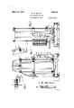
Figure 1 is a side elevation of the improved fire fighting apparatus in its normal non-discharging position, parts being. broken away; I
Figure 2 is a side elevation of the improved fire fighting apparatus in its discharging position, the view being at right angles to Figure 1;
Figure 3 is a detail sectional view illustrating the means for rotatably supporting the fireextinguisher;
Figure 4 is a detail elevation illustrating the means to look a fire extinguisher to the carriage;
Figure 5 is a perspective of the improved fire fighting apparatus, the fire extinguisher being removed;
Figure 6 is a plan View of the improved fire fighting apparatus;
Figure 7 is a group perspective illustrating the means to lock the apparatus and the basket for the fire extinguisher in a fixed position;
Figure 8 is adetail sectional view through the basket locking latch and the operating means therefor r Figure 9 is a detail horizontal sectional view taken on line 99 of Figure 8.
Figure 10 is a detail sectional view through a stop member embodied in the invention.
In the drawings, wherein for the purpose of illustration is shown a preferred embodiment of the invention, the numeral5 desig nates a basemounted on rollers 6 preferably of the type shown in Figures 1 and 2 so that the apparatus may be moved to the proper place in case of an emergency with but a slight eliort on the part of the operator. This permits the apparatus to be operated by women, children and invalids, and to move chemical containing tanks of comparatively large capacity to the scene of a fire. A
The base is provided with a pair of standards 8 which as shown in Figure S are somewhat of U'shaped formation and have their inner sidesprovided with laterally projecting flanges for strengthening purposes and other purposes which will hereinafter fully appear. First, the upper portions of the standards 8 receive blocks 9 constituting what might be said to he bearings for the trunnions 10 of a basket or container 11 for a chemical containing tank of conventional or other design. Suitable straps 12 are extended over the terminals of the trunnions 10 and may be secured in any desired manner to the upper portions of the standards so as to hold the basket 11 in place between the standards.
It is believed to be obvious that a chemical storage tank is adapted to be detachably received in the basket 11 and may be locked therein by suitable fastening members 16, the upper portions of which are, as shown in Figures '3 and 4, provided with bills which extend over and engage the adjacent end of the tank. a The lower portions of the hooks 16 may be extended through cars 17 at the upper portion of the basket and may be provided with thumb nuts 19 by means of which the hooks may be securely anchored to the tank. Therefore, when thebasket' containing the tank is quickly inverted the tank will remain in place in the basket.
At this point particular attention is d1- rected to Figures 1 and 5 which illustrate that the terminal of one trunnion is flattened and apertured to define a hose nozzle receiving loop 20 arranged directly above and in line with the channel of the adjacent stand ard for the reception of the nozzle 21 of the hose. When the hose nozzle is extended through the loop 20 and into the channel as clearly shown in Figure 3, the apparatus is locked against turning. It will, therefore, be seen that preparatory to the discharge of the fire extinguishing fluid the operator must remove the nozzle 21 and hold the same in his or her hand. It is important to note that the basket is provided with a hose rack or container 25 by means of which a hose of possibly twenty or twenty-five feet may be conveniently carried. When the basket and the tank are inverted, the hose will be dropped to the floor so that the same may be unreeled.
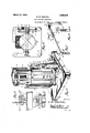
Attention is now directed to Figures 2, 5, 6 and 7 which illustrate that a shaft 30 extends across the top of the base and is provided with a foot pedal 31 by means of which a lug 32 on the shaft may be rocked in a clockwise direction. Figure 8 clearly illustrates that the lug 32 extends up into a slot 33 in a latch or bolt 34 so that when the shaft 30 is rocked the latch will be re tracted. When the latch is thus retracted it is withdrawn from engagement with the lug or projection 36 on the adjacent portion of the basket. The forward terminal portion of the latch 34 cooperates with a lug 37 carried by one of the flanges of the standard in the formation of what might be said to be a socket in which the projection 36 is received. Thus when the basket is in its normal upright position the projection 36 of the same is confined between the lug 37 and the forward terminal portion of the latch 34 and the basket is held against turning. However, when it is desired to release the basket for turning it is merely necessary to depress the foot pedal 31 and bring about the turning of the shaft 30 so that the latch is retracted fromengagement with the projection 36. This, of course, permits the basket to be easily inverted so that the parts occupy the position shown in Figure 2.
When the basket is thus moved to the position shown in Figure 2 a projection 40 on the upper portion of the basket is engaged with the terminal of a latch 41, which latch cooperates'with a lug similar to the lug 37 in the formation of a socket by means of which the projection 40 is securely engaged to hold the basket in an inverted position.
When it is desired to release the basket to bring about the return of the tank to its normal non-discharging position it is merely necessary to pull upwardly on a link 45 slidably attached to one of the standards by a strap 46. Figure 1 clearly illustrates that the lower portion of the link 45 is pivotally connected to a bell crank 47 and that the bell crank is extended into a slot in the latch 41 so that the elevation of the link 45 will result in the retraction of the latch 41. A suitable housing or sheath 49 is employed to slidably support the latch at one side of one of the standards. The upper portion of the link 45 is provided with a finger receiving aperture which registers with a slot 52 in the adjacent side of the standard. This makes it a simple matter to engage the link 45 and pull the same upwardly.
The shaft 30 is, as shown in Figure 5, received in a housing 60, the ends of which are enlarged for the reception of disks 61 having cranks 62 to which links 64 are connected. The links 64 might be said to be telescopic since each link consists of a pair of sections having inwardly directed flanges between which a coil spring 66 is confined. When the pedal 31 is depressed the links 64 are moved downwardly so that the rubber feet 68 of the same will be engaged with the floor. The presence of the spring 66 makes it possible for the shaft 30 to continue to turn until the latch 34 has been fully retracted.
As clearly shown in Figure 7, the shaft 30 is provided with a coil spring 79, one end of which engages the base 5 and the other end being engaged with the under side of the pedal to normallyhold the pedal in an elevated position and to normally hold the latch 34 in an advanced position. In other words, when the foot pressure on the pedal 31 is released the spring 7 9 will immediately return the pedal to the elevated position shown in Figure 5.
An important feature of the invention resides in the provision of the lateral extension of one of the flanges of one of the standards 8 so that the extension comes immediately in front of the pedal 31. The lateral extension which is designated by the numeral 80 prevents the foot of the operator from moving to a position beneath the basket when the basket is being turned. In other words, the lateral extension constitutes what might be said to be a safety guard to space the foot of the operator from engagement with the basket.
In the operation of the improved fire fighting apparatus, a person desiring to move the apparatus to the scene of a fire has only to push the same and owing to the presence of the rollers 6 only a limited effort is required. Preparatory to the movement of the tank to discharging position, the nozzle 21 is withdrawn from its socket and held in the hand of the operator while the foot is engaged with the pedal 31 and the shaft is turned to bring about the release of ill) cally locked in inverted position as shown in Figure 2. Of course, simultaneously with the release of the latch 34 the links 64 are moved into engagement with the floor to hold the apparatus in place.
Having thus described the invention, what is claimed is: i
1. A fire fighting apparatus comprising a mobile base, standards mounted on the base, a basket having trunnions connected to the standards, a latch for engaging said basket to hold the same against movement, a manually actuated member connected to said base and forming a means whereby the latch may be retracted, and floor engaging means connected to said manually actuated member and actuated thereby to engage the floor for securing the base in position.
2. A fire fighting apparatus comprising a base, standards mounted on the base, a
spring actuated latch carried by one of the standards, a basket rotatably connectedto the standards and having a projection adapted to be engaged by said latch, a shaft having a lug adapted to engage said latch, and a foot actuated pedal connected to said shaft and adapted to be depressed to retract said latch.
3. A fire fighting apparatus comprising a base, standards mounted on the base, a spring actuated latch carried by one of the standards, a basket rotatably connected to the standards and having a projection adapted to be engaged by said latch, a shaft having a lug adapted to engage said latch, a foot actuated pedal connected to said shaft and adapted to be depressed to retract said latch, and fioor engaging means connected to said shaft and normally supported in .a position out of engagement with a floor.
4. A fire fighting apparatus comprising a base, standards mounted on the base, a basket having trunnions rotatably connected to the standards, a latch slidably carried by one of said standards and having a slot, an
operating shaft having a lug extending into said slot and engaged with one wall of the same whereby the movement of the shaft will retract said latch, and a spring to advance the latch into engagement with said basket.
5. A fire fighting apparatus comprising a base, standards mounted on the base, a basket having trunnions rotatably connected to the standards, a latch slidably carried by one of said standards and having a slot, an operating shaft having a lug extending into said slot and engaged with one wall of the same whereby the movement of the shaft will retract said latch, a spring carried by said shaft and engageable with said base for advancing the latch into engagement with said basket, and a pedal connected to the shaft and forming a means whereby the same may be rocked.
6. A fire fighting apparatus comprising in combination, a base, standards mounted on the base, a latch, a basket rotatably connect ed to the standards and having a projection adapted to be engaged by said latch, a shaft having a lug adapted to engage said latch, a foot actuated pedal connected to said shaft and adapted to be depressed to retract said latch, and floor engaging means connected to said shaft and normally supported in a position out of engagement with a floor, said fioor engaging means being adapted to be moved to floor engaging position by the depression of said pedal.
7 A fire fighting apparatus comprising a base, standards mounted on the base, a hasket rotatably connected to the standards, a latch for engaging said basket, a rotatably journalled shaft having means adapted to engage said latch, and afoot actuated pedal connected to said shaft and adapted to be depressed to retract said latch.
In testimony whereof I afiix my signature.
WALTER M. NEWTON.
Priority Applications (1)
| Application Number | Priority Date | Filing Date | Title |
|---|---|---|---|
| US95095A US1663608A (en) | 1926-03-16 | 1926-03-16 | Fire-fighting apparatus |
Applications Claiming Priority (1)
| Application Number | Priority Date | Filing Date | Title |
|---|---|---|---|
| US95095A US1663608A (en) | 1926-03-16 | 1926-03-16 | Fire-fighting apparatus |
Publications (1)
| Publication Number | Publication Date |
|---|---|
| US1663608A true US1663608A (en) | 1928-03-27 |
Family
ID=22249538
Family Applications (1)
| Application Number | Title | Priority Date | Filing Date |
|---|---|---|---|
| US95095A Expired - Lifetime US1663608A (en) | 1926-03-16 | 1926-03-16 | Fire-fighting apparatus |
Country Status (1)
| Country | Link |
|---|---|
| US (1) | US1663608A (en) |
Cited By (1)
| Publication number | Priority date | Publication date | Assignee | Title |
|---|---|---|---|---|
| US20160195259A1 (en) * | 2015-01-02 | 2016-07-07 | Julie McCulloch Burton | Swiveling candle holder and preserver |
-
1926
- 1926-03-16 US US95095A patent/US1663608A/en not_active Expired - Lifetime
Cited By (1)
| Publication number | Priority date | Publication date | Assignee | Title |
|---|---|---|---|---|
| US20160195259A1 (en) * | 2015-01-02 | 2016-07-07 | Julie McCulloch Burton | Swiveling candle holder and preserver |
Similar Documents
| Publication | Publication Date | Title |
|---|---|---|
| US3667714A (en) | Tank support | |
| US3224720A (en) | Combined handle lock and bracket for fire extinguishers | |
| US6193033B1 (en) | Towable carrying case | |
| US9187108B2 (en) | Folding cart for portable grill | |
| US3064990A (en) | Hand truck | |
| US3712417A (en) | Inflatable evacuation slide | |
| US10543863B2 (en) | Mobile cart for an organ container | |
| US2841438A (en) | Stretcher having a collapsible undercarriage | |
| WO1999034703A1 (en) | Lower profile towable luggage | |
| US1663608A (en) | Fire-fighting apparatus | |
| US2692636A (en) | Combination automobile mechanic's creeper and stool | |
| US3057655A (en) | Progressively collapsible cot | |
| US3127624A (en) | Automatically-inflatable life preserver | |
| KR101643594B1 (en) | Folding Stretcher Guide Apparatus for Ambulance | |
| US3572441A (en) | Liquid discharge tank adapted to be hung and transported | |
| US3162867A (en) | Automatic step for beds | |
| US5320567A (en) | Aquatic rescue device | |
| KR20120028070A (en) | Hose transfer apparatus for fire-fighting | |
| US2309735A (en) | Vehicle construction | |
| JP2019080707A (en) | Portable type fire extinguisher | |
| JPH11239625A (en) | Rescuing gangway | |
| US3189123A (en) | Folding ladder | |
| US3209442A (en) | Bow stringing device | |
| CN211513223U (en) | Super high-rise building fire personnel safety evacuation rescue vehicle | |
| JP2001149491A (en) | Fire-extinguisher moving utensil |