US1663607A - Electric power transmitter - Google Patents
Electric power transmitter Download PDFInfo
- Publication number
- US1663607A US1663607A US751299A US75129924A US1663607A US 1663607 A US1663607 A US 1663607A US 751299 A US751299 A US 751299A US 75129924 A US75129924 A US 75129924A US 1663607 A US1663607 A US 1663607A
- Authority
- US
- United States
- Prior art keywords
- clutch
- frame
- driven
- motor
- shaft
- Prior art date
- Legal status (The legal status is an assumption and is not a legal conclusion. Google has not performed a legal analysis and makes no representation as to the accuracy of the status listed.)
- Expired - Lifetime
Links
- 241000239290 Araneae Species 0.000 description 5
- 238000009958 sewing Methods 0.000 description 4
- 238000004804 winding Methods 0.000 description 4
- XEEYBQQBJWHFJM-UHFFFAOYSA-N Iron Chemical compound [Fe] XEEYBQQBJWHFJM-UHFFFAOYSA-N 0.000 description 2
- 239000004020 conductor Substances 0.000 description 2
- 239000004519 grease Substances 0.000 description 2
- 238000003475 lamination Methods 0.000 description 2
- 239000010985 leather Substances 0.000 description 2
- 239000000314 lubricant Substances 0.000 description 2
- 230000001050 lubricating effect Effects 0.000 description 2
- 241000507564 Aplanes Species 0.000 description 1
- RYGMFSIKBFXOCR-UHFFFAOYSA-N Copper Chemical compound [Cu] RYGMFSIKBFXOCR-UHFFFAOYSA-N 0.000 description 1
- 230000000694 effects Effects 0.000 description 1
- 238000009434 installation Methods 0.000 description 1
- 229910052742 iron Inorganic materials 0.000 description 1
- 238000004519 manufacturing process Methods 0.000 description 1
Images
Classifications
-
- H—ELECTRICITY
- H02—GENERATION; CONVERSION OR DISTRIBUTION OF ELECTRIC POWER
- H02K—DYNAMO-ELECTRIC MACHINES
- H02K7/00—Arrangements for handling mechanical energy structurally associated with dynamo-electric machines, e.g. structural association with mechanical driving motors or auxiliary dynamo-electric machines
- H02K7/10—Structural association with clutches, brakes, gears, pulleys or mechanical starters
- H02K7/112—Structural association with clutches, brakes, gears, pulleys or mechanical starters with friction clutches in combination with brakes
Definitions
- This invention relates to electric power transmitters of the type used in the individual drive and control of small machines such as sewing machines.
- Electric power-transmitters such as heretofore employed for this work have, however, commonl been constructed with a heavy fly-whee to effect the desired quick pick-up of the driven machine when the clutch elements are engaged; a quick pick-up being an essential requirement of a modern transmitter.
- This heavy fly wheel or weighted member has been mounted on or keyed to the motor-shaft so that the power from the rotary motor element had to be transmitted to the fly-wheel and from the flyswheel to the driven machine through a shaft and key connection. This adds to the size, weight and cost of manufacture of the transmitter.
- the rotary element of the motor may itself be formed with a driving friction clutch-face a ainst which a driven clutchmember carrying the belt-pulley is moved by a connection with the usual treadle-rod.
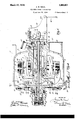
- Fig. 1 is through an electric power-transmitter em- Thus," there is no driving through keys or shafts; the belt-pulley being driven directfrom the rotary element of the motor through the friction-clutch.
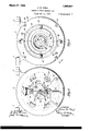
- Figs. 2 and 3 are respectively right and left-end elevations of the transmitter shown in F i 1..
- Fig. 4- is a fragmentary section on the Iine 4, 4, Fig. 3.
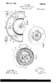
- Fig. 5 is an internal sectional view on the line 5, 5, Fig. 1, showing the external rotary element detached from its supporting s ider.
- Fig. 6 is a section on the line 6-6, F ig. 1, with the driven clutch-element removed
- Fig. 7 is a section on the line 7, 7, Fig. 1; the windings being removed.
- the transmitter is formed with a hollow cylindrical frame 1 having the attaching feet 2 and the inwardly extending central tubular portion 3011 which is tightly fitted the stationary electro-magnetic element 4 of an electric motor.
- the element 4 may comprise a stack of externally toothed laminations which are assembled on the tube 5 having its ends spun over at 6, 6 and provided with a winding 7 ofan desired type.
- the winding 7 is the usual four-pole three-phase winding.
- the rotary electro-magnetic member of the motor is disposed externally of the stationary member 4 and is constituted by an ordinary ring type squirrel-cage rotor including the iron laminations 8, end-conductor rings 9 and conductor bars 10.
- the rotor-element 8 is secured by screws 11 to the spider 12 which is tightly fitted to and carried by the tubular shaft 13 journaled in the ball bearings 14, 15 within the tubular frame-portion 3.
- the shaft 13 is formed with an integral collar 16 and, in assembling 15, 15", are slipped on the shaft 13 in t e order named and are all tightened in position by means of the nut 18 which is screwed onto the threaded extremity 19 of the shaft 13.
- the ball-bearing 14 constitutes the main working bearing and its outer race 14" is clamped tlghtly against the shoulder in the tubular frame-portion 3 by the retaining ring 21 which is secured to the inner end of screws :23, Fig. 5.
- the ring 21 is formed with a groove in which is fitted a felt wipmg ring 22 engaging the hub 23 of the sp1der 12 to prevent escape of lubricating grease with which the tubular frame-member 3 is filled.
- the support 12 or spider for the rotary motor-element 8 is grooved at 24 to receive the friction leather 25 constituting a driving friction clutch-face with which mates the clutch-face 26 of the driven clutch-member 27 fitted'to slide and rotate upon and relative to the shaft .13, and having mounted on it the belt pulley 28.
- the driven clutch-member 27 is preferably formed with aplane outer face 29 which 18 ada ted to engage the leather face 30 of a bra e-ring 31 whichnis carried by the diametrically op osed trunnion-screws 32 pro jecti'ng inwar ly from the intermediate ring 33 supported in turnbythe diametrically opposed trunnion-screws 34 spaced 90 from the screws 32 and projecting inwardl from the end-bonnet '35 which is detacha 1y secured to-the frame 1 by means of screws 36.
- the cylindrical extremities 37 of the screws 34 are (preferably formed eccentric to the threade brake-ring 31 may be adjusted axially of cap 39 and lock ring 40.
- the driven clutch-member 27 has a hubportion 38 which extends through the pulley 28 and is threaded externall to receive the ispo'sed witlin the cap 39 is a ball thrust-bearing comprising the race 41 which bears against the end of the hub 38 of the driven clutch-member 27.
- the shaft 13 is also formed externally with a lubricant channel 50 extending lengthwise of the bearing surface between such shaft and the driven clutch-member 27. 'This channel is the tubular frame-portion 3 by shanks of such screws, so that the,
- the lever-plate 54 brace the opposite faces of the lever-plate 54 and are connected by the screw-pin 55 which passes through the vertical slot 56 in the lever-plate 54.
- the lever-plate 54 is fulcrumed at 57 on the bifurcated bracket-arm 58 projecting from the cap-member 52 and has an upwardly extending arm 59 which is connected by the spring 60 to the ear 61 on the plate 52.
- a treadle rod 62 is connected to the arm 63 of the lever 54.
- cap 52 is secured to the frame 1 by four screws 64, Fig. 2, spaced 90 apart, and that the frame is tapped at points 65, spaced 45 from the positions of such screws shown in Fig. 2, to permit the ca 52 and parts carried thereby to be shifte 45 relative to the plane of the feet 2, thereb adap ing the transmitter to be secured to t e incline trough-wall of a trough-table while maintaining vertically the plane of operation of the lever 54.
- the interior of the tubular-frame element 3 is to be supplied with lubricating grease which may be introduced through the duct 66 by means of the grease-cup 67.
- the motor is effectively ventilated by forming the spider with openings 68 which, by centrifugal action, draw air through the air gap 69. and through the ventilating grooves 70 cut longitudinally of the tubular frame-element 3.
- the frame 1 is provided at one end with ventilating openin 71.
- the openings between the driven c utc member 27 the rings 31, 33 and end-bonnet 35 afford ventilating openings at the other end of the frame.
- the frame ma be formed with a compartment 72 closed by a coverplate 72' for the connections between the current supply lines and the motor terminal wires.
- a feature of importance is the quick 'ickup or large fly-wheel eifect secured wit out the use of an additional fiy-wheel; the weight of the external rotating electro-magnetic member 8 acting in conjunction with the manually operated friction clutch to ac celerate the driven machine from a standlutch-operating rod 45 passesstill to full speed in a fraction of a second.
- a unitary electric under driver for machine tables comprising a hollow cylindrical frame havin external attaching means, a hollow shaft within and coaxial with said frame, stationary and rotar motor elements within said frame coaxia with said shaft, said rotary motor element having a drivin clutch face, a driven clutch member and It pulley carried by said shaft at one end of said hollow frame, a stationary brake carried by said frame at the same end of the latter as the driven clutch member, a treadle controlled lever carried at the opposite end of said frame, and a push-and-pull rod passing through said hollow shaft and connected at its op osite ends to said driven clutch member and treadle controlled lever to transmit clutch and brake engaging movements in opposite directions to said driven clutch member.
- a unitaig electric power-transmitter comprising a ollow frame having external supporting means and an internal tubular portion, a stationary motor-element mounted within said hollow frame on said internal tubular ortion, a rotary motor-element disposed within said hollow frame externally of said stationary motor-element, a shaft coaxial with said tubular frame portion and carrying said rotary motor-element, a combined driven member and belt-pulls journaled coaxially with said shaft, a f ri clutch connection between said driven memher and total; motor-element and a brake carried by sai frame for stop ing said combined driven member and belt-pulley.
- a unitary electric power-transmitter comprising a hollow frame having external supporting means and an inwardly projecting tubular portion, a stationary motor-element fixed to said tubular portion within said hollow frame, a rotary motor-element ction disposed within said hollow frame external ly of said stationary motor-element, a shaft coaxial with said tubular portion, a spider coaxial with said shaft and carrying said rotary motor-element, said spider having a driving friction clutch-face, a driven clutch member and belt-pulley rotatably and slidably mounted coaxially with said shaft, and manually operated means for sliding said driven clutch-member.
- An electric power-transmitter having, in combination, a hollow frame including a removable end-bonnet ring, an intermediate ring pivotally carried by said end-bonnet ring, a brake-ring pivotally carried by said intermediate ring, a shaft journaled in said frame transversely of the plane of said brake-ring, a driven clutch-element journaled on and movable endwise of said shaft and having a face opposed to said brakering and a hub-portion projecting throu h said brake-ring, a motor-driven live clutc member within said frame, and manually o erated means for sliding said driven c utch-member on said shaft.
- An electric power-transmitter having, in combination, a motor-driven live clutchelement and shaft a stationa self-aligning brake-ring s aced from sai live clutch-' element, a riven clutch-element slidably and rotatably journaled on said shaft and disposed between said brake-ring and live clutch-element, and means for shifting said driven clutch-element into engagement with either said live clutch-element or brake-ring.
- An electric ower-transmitter havin a hollow frame formed with an interna tubular portion, ooacting electro-magnetic stationary and rotary motor elements carried by said tubular frame portion, an end ca detachably closing the outer end of said tu ular frame portion, a driven member, a friction clutch connection between the retary motor element and said driven mem- Ill ber, a clutch-operating rod disposed coaxi- Y tubular portion, coacting electromagnetic stationary and rotary motor-elements carried by said tubular rame portion, an endca detachably closing the outer end of said tu ular frame portion, a driven member, a friction clutch connection between the roby said frame-end member, astationary motor-member mounted on said internal tubular frame portion, a rotary motor-member journaled within said frame coaxially with said internal tubular frame portion and having adriving clutch face, a driven clutch-member coaxial with said rotary motor member and cooperatively related with said brake, means for shifting
Landscapes
- Engineering & Computer Science (AREA)
- Power Engineering (AREA)
- Connection Of Motors, Electrical Generators, Mechanical Devices, And The Like (AREA)
Description
March 27, 1928.
J. M. NAUL ELECTRIC POWER TRANSMITTER Filed Nov. 2 1924 3 Sheets-Sheet 1 km p INVENTOR .7" L/EY 7} And TT NEY March 27, 1928.
J. M. NAUL ELECTRIC POWER TRANSMITTER Filed Nov. 21. 1924 5 Sheets-Sheet 2 INVENTOR ZLW I WITN ES ES ATTORNEY March 27, 1928.
1,663,607 J. M. NAUL ELECTRIC POWER TRANSMITTER Filed Nov. 21. 1924 s Sheets-Sheet 5 {g INVENTOR 7ZM M55 35 Patented Mar. 27, 1928.
UNITED STATES Q 6 1,663,607 PATENT OFFICE.
JAMES M. NAUL, OF PLAINFIELD, NEW JERSEY, AS SIGNOB TO THE SINGER mu- ..FACTUBING COMPANY, OF ELIZABETH, NEW JERSEY, A COBRORAT'ION O! m JERSEY.
ELECTRIC POWER TRANSMITTER.
Application filed November 21, 1924. Serial No. 751,889.
This invention relates to electric power transmitters of the type used in the individual drive and control of small machines such as sewing machines.
6 In some factories where sewing machines are used, it is customary to arranged the machines in rows on long tables known as power-tables. Such tables have a motordriven line-shaft running lengthwise thereof and carrying driving pulleys which are belted to treadle-controlled clutches known as underdrivers or power-transmitters; the driven elements of such transmitters being belted to the respective sewing machines. In
15 other installations the line shaft runs through the series of power-transmitters and is directly connected to the driving elementof each transmitter, thereby eliminating beltlosses between the line-shaft and the transmitter. The modern tendency, however, is toward the individual motor drive, the line shafting and its bearing losses being eliminated and an individual motor, and transmitter unit or' electric power-transmitter provided for each sewing machine.
Electric power-transmitters such as heretofore employed for this work have, however, commonl been constructed with a heavy fly-whee to effect the desired quick pick-up of the driven machine when the clutch elements are engaged; a quick pick-up being an essential requirement of a modern transmitter. This heavy fly wheel or weighted member has been mounted on or keyed to the motor-shaft so that the power from the rotary motor element had to be transmitted to the fly-wheel and from the flyswheel to the driven machine through a shaft and key connection. This adds to the size, weight and cost of manufacture of the transmitter.
I have combined in a compact arrangement, in an electric transmitter unit,a manually controlled friction clutch with an electric motor having its rotary element disposed externally of its stationary element, so that a quick pick-up may be secured, thereby meeting the requirements of the trade in this respect, without the use of an additional flywheel. By virtue of the present arrangement, the rotary element of the motor may itself be formed with a driving friction clutch-face a ainst which a driven clutchmember carrying the belt-pulley is moved by a connection with the usual treadle-rod.
Fig. 1 is through an electric power-transmitter em- Thus," there is no driving through keys or shafts; the belt-pulley being driven directfrom the rotary element of the motor through the friction-clutch.
Referring to the accompanying drawings, a longitudinal vertical section bodying the invention. Figs. 2 and 3 are respectively right and left-end elevations of the transmitter shown in F i 1.. Fig. 4-is a fragmentary section on the Iine 4, 4, Fig. 3. Fig. 5 is an internal sectional view on the line 5, 5, Fig. 1, showing the external rotary element detached from its supporting s ider. Fig. 6 is a section on the line 6-6, F ig. 1, with the driven clutch-element removed, and Fig. 7 is a section on the line 7, 7, Fig. 1; the windings being removed.
In the preferredembodiment of the invention illustrated, the transmitter is formed with a hollow cylindrical frame 1 having the attaching feet 2 and the inwardly extending central tubular portion 3011 which is tightly fitted the stationary electro-magnetic element 4 of an electric motor. The element 4 may comprise a stack of externally toothed laminations which are assembled on the tube 5 having its ends spun over at 6, 6 and provided with a winding 7 ofan desired type. In the particular motor i lustrated the winding 7 is the usual four-pole three-phase winding.
The rotary electro-magnetic member of the motor is disposed externally of the stationary member 4 and is constituted by an ordinary ring type squirrel-cage rotor including the iron laminations 8, end-conductor rings 9 and conductor bars 10. The rotor-element 8 is secured by screws 11 to the spider 12 which is tightly fitted to and carried by the tubular shaft 13 journaled in the ball bearings 14, 15 within the tubular frame-portion 3. The shaft 13 is formed with an integral collar 16 and, in assembling 15, 15", are slipped on the shaft 13 in t e order named and are all tightened in position by means of the nut 18 which is screwed onto the threaded extremity 19 of the shaft 13. The ball-bearing 14 constitutes the main working bearing and its outer race 14" is clamped tlghtly against the shoulder in the tubular frame-portion 3 by the retaining ring 21 which is secured to the inner end of screws :23, Fig. 5. The ring 21 is formed with a groove in which is fitted a felt wipmg ring 22 engaging the hub 23 of the sp1der 12 to prevent escape of lubricating grease with which the tubular frame-member 3 is filled. The support 12 or spider for the rotary motor-element 8 is grooved at 24 to receive the friction leather 25 constituting a driving friction clutch-face with which mates the clutch-face 26 of the driven clutch-member 27 fitted'to slide and rotate upon and relative to the shaft .13, and having mounted on it the belt pulley 28. V
The driven clutch-member 27 is preferably formed with aplane outer face 29 which 18 ada ted to engage the leather face 30 of a bra e-ring 31 whichnis carried by the diametrically op osed trunnion-screws 32 pro jecti'ng inwar ly from the intermediate ring 33 supported in turnbythe diametrically opposed trunnion-screws 34 spaced 90 from the screws 32 and projecting inwardl from the end-bonnet '35 which is detacha 1y secured to-the frame 1 by means of screws 36.
The cylindrical extremities 37 of the screws 34 are (preferably formed eccentric to the threade brake-ring 31 may be adjusted axially of cap 39 and lock ring 40.
the shaft 13 to compensate for wear on the friction surfaces andmaintain the desired amount of end-play of the driven clutchmember 27.
- The driven clutch-member 27 has a hubportion 38 which extends through the pulley 28 and is threaded externall to receive the ispo'sed witlin the cap 39 is a ball thrust-bearing comprising the race 41 which bears against the end of the hub 38 of the driven clutch-member 27.
'Disposed'within the race 41 are the balls 42 j and the hardened washer 43 held in place by the ex ansible retaining ring 44. Passing throug the hollow shaft 13 is the-manually operated push-and-pull rod 45 the headed extremity 46 of which engages the washer 43 to exert pressure on the ball thrust-bearing 42 and shift the driven clutch-member 27 into engagement with the driving clutchmember 12. The cap 39 is ad'usted lengthwise of the hub 38 to secure a s ight working clearance between the rounded end of the head 46 and the inner end-wall 47 of said cap. A grease-cup 48 is screwed onto the cap 39 and forces lubricant to the ball thrust-bearing through the apertures 49 in the end-wallof such cap. The shaft 13 is also formed externally with a lubricant channel 50 extending lengthwise of the bearing surface between such shaft and the driven clutch-member 27. 'This channel is the tubular frame-portion 3 by shanks of such screws, so that the,
brace the opposite faces of the lever-plate 54 and are connected by the screw-pin 55 which passes through the vertical slot 56 in the lever-plate 54. The lever-plate 54 is fulcrumed at 57 on the bifurcated bracket-arm 58 projecting from the cap-member 52 and has an upwardly extending arm 59 which is connected by the spring 60 to the ear 61 on the plate 52. A treadle rod 62 is connected to the arm 63 of the lever 54.
It will be noted that the cap 52 is secured to the frame 1 by four screws 64, Fig. 2, spaced 90 apart, and that the frame is tapped at points 65, spaced 45 from the positions of such screws shown in Fig. 2, to permit the ca 52 and parts carried thereby to be shifte 45 relative to the plane of the feet 2, thereb adap ing the transmitter to be secured to t e incline trough-wall of a trough-table while maintaining vertically the plane of operation of the lever 54.
The interior of the tubular-frame element 3 is to be supplied with lubricating grease which may be introduced through the duct 66 by means of the grease-cup 67.
The motor is effectively ventilated by forming the spider with openings 68 which, by centrifugal action, draw air through the air gap 69. and through the ventilating grooves 70 cut longitudinally of the tubular frame-element 3. The frame 1, is provided at one end with ventilating openin 71. The openings between the driven c utc member 27 the rings 31, 33 and end-bonnet 35 afford ventilating openings at the other end of the frame. The frame ma be formed with a compartment 72 closed by a coverplate 72' for the connections between the current supply lines and the motor terminal wires.
A feature of importance is the quick 'ickup or large fly-wheel eifect secured wit out the use of an additional fiy-wheel; the weight of the external rotating electro-magnetic member 8 acting in conjunction with the manually operated friction clutch to ac celerate the driven machine from a standlutch-operating rod 45 passesstill to full speed in a fraction of a second.
Another feature of importance is the 'marked compactness of the outfit which particularly fits it for use as an underdriver in I clutch-member coaxial with said rotary motor-member mounted on said internal tubular frame ortion, a rotary motor member journaled within said frame coaxially with said internal tubular frame portion and having a driving clutch face, a driven motor member and cooperatively related with said brake, means for shifting said driven clutch member into engagement with said driving member, and a belt-pulley on said driven clutch-member.
2. A unitary electric under driver for machine tables comprising a hollow cylindrical frame havin external attaching means, a hollow shaft within and coaxial with said frame, stationary and rotar motor elements within said frame coaxia with said shaft, said rotary motor element having a drivin clutch face, a driven clutch member and It pulley carried by said shaft at one end of said hollow frame, a stationary brake carried by said frame at the same end of the latter as the driven clutch member, a treadle controlled lever carried at the opposite end of said frame, and a push-and-pull rod passing through said hollow shaft and connected at its op osite ends to said driven clutch member and treadle controlled lever to transmit clutch and brake engaging movements in opposite directions to said driven clutch member.
3. A unitaig electric power-transmitter comprising a ollow frame having external supporting means and an internal tubular portion, a stationary motor-element mounted within said hollow frame on said internal tubular ortion, a rotary motor-element disposed within said hollow frame externally of said stationary motor-element, a shaft coaxial with said tubular frame portion and carrying said rotary motor-element, a combined driven member and belt-pulls journaled coaxially with said shaft, a f ri clutch connection between said driven memher and total; motor-element and a brake carried by sai frame for stop ing said combined driven member and belt-pulley.
4. A unitary electric power-transmitter comprising a hollow frame having external supporting means and an inwardly projecting tubular portion, a stationary motor-element fixed to said tubular portion within said hollow frame, a rotary motor-element ction disposed within said hollow frame external ly of said stationary motor-element, a shaft coaxial with said tubular portion, a spider coaxial with said shaft and carrying said rotary motor-element, said spider having a driving friction clutch-face, a driven clutch member and belt-pulley rotatably and slidably mounted coaxially with said shaft, and manually operated means for sliding said driven clutch-member.
5; An electric power-transmitter having, in combination, a hollow frame including a removable end-bonnet ring, an intermediate ring pivotally carried by said end-bonnet ring, a brake-ring pivotally carried by said intermediate ring, a shaft journaled in said frame transversely of the plane of said brake-ring, a driven clutch-element journaled on and movable endwise of said shaft and having a face opposed to said brakering and a hub-portion projecting throu h said brake-ring, a motor-driven live clutc member within said frame, and manually o erated means for sliding said driven c utch-member on said shaft.
6. An electric power-transmitter having, in combination, a motor-driven live clutchelement and shaft a stationa self-aligning brake-ring s aced from sai live clutch-' element, a riven clutch-element slidably and rotatably journaled on said shaft and disposed between said brake-ring and live clutch-element, and means for shifting said driven clutch-element into engagement with either said live clutch-element or brake-ring.
7. An electric power-transmitter havin in combination, a motor-driven live clutc element, a self-aligning stationary brakering substantially coaxial with and spaced from said live clutch-element, and a manually shiftable driven clutch-element interposed between said live clutch-element and rake-ring.
8. An electric ower-transmitter havin a hollow frame formed with an interna tubular portion, ooacting electro-magnetic stationary and rotary motor elements carried by said tubular frame portion, an end ca detachably closing the outer end of said tu ular frame portion, a driven member, a friction clutch connection between the retary motor element and said driven mem- Ill ber, a clutch-operating rod disposed coaxi- Y tubular portion, coacting electromagnetic stationary and rotary motor-elements carried by said tubular rame portion, an endca detachably closing the outer end of said tu ular frame portion, a driven member, a friction clutch connection between the roby said frame-end member, astationary motor-member mounted on said internal tubular frame portion, a rotary motor-member journaled within said frame coaxially with said internal tubular frame portion and having adriving clutch face, a driven clutch-member coaxial with said rotary motor member and cooperatively related with said brake, means for shifting said driven clutch member .into engagement with said driving member, and a' belt-pulley on said driven clutch-member.
In testimony whereof, I have signed my name to this specification.
JAMES M. NAUL.
Priority Applications (1)
| Application Number | Priority Date | Filing Date | Title |
|---|---|---|---|
| US751299A US1663607A (en) | 1924-11-21 | 1924-11-21 | Electric power transmitter |
Applications Claiming Priority (1)
| Application Number | Priority Date | Filing Date | Title |
|---|---|---|---|
| US751299A US1663607A (en) | 1924-11-21 | 1924-11-21 | Electric power transmitter |
Publications (1)
| Publication Number | Publication Date |
|---|---|
| US1663607A true US1663607A (en) | 1928-03-27 |
Family
ID=25021385
Family Applications (1)
| Application Number | Title | Priority Date | Filing Date |
|---|---|---|---|
| US751299A Expired - Lifetime US1663607A (en) | 1924-11-21 | 1924-11-21 | Electric power transmitter |
Country Status (1)
| Country | Link |
|---|---|
| US (1) | US1663607A (en) |
Cited By (9)
| Publication number | Priority date | Publication date | Assignee | Title |
|---|---|---|---|---|
| US2549275A (en) * | 1946-04-11 | 1951-04-17 | Toledo Scale Co | Coffee mill |
| US2617051A (en) * | 1951-02-14 | 1952-11-04 | Singer Mfg Co | Clutch brake motor |
| US2740910A (en) * | 1952-05-02 | 1956-04-03 | Gen Electric | Rotor memeber for dynamoelectric machine |
| US2746555A (en) * | 1950-09-05 | 1956-05-22 | Adrienne M Sherwood | Wheel drive transmission and clutch arrangement |
| US2847592A (en) * | 1955-03-23 | 1958-08-12 | Gerbaud Auguste Henri | Motor for industrial and household sewing machines |
| US3447005A (en) * | 1965-07-30 | 1969-05-27 | Mitsubishi Electric Corp | Motor clutch brake device |
| US11268585B2 (en) * | 2018-03-02 | 2022-03-08 | Honda Motor Co., Ltd. | Driving apparatus |
| US11306791B2 (en) | 2018-03-02 | 2022-04-19 | Honda Motor Co., Ltd. | Driving apparatus |
| US12044291B2 (en) | 2018-03-02 | 2024-07-23 | Honda Motor Co., Ltd. | Driving apparatus |
-
1924
- 1924-11-21 US US751299A patent/US1663607A/en not_active Expired - Lifetime
Cited By (9)
| Publication number | Priority date | Publication date | Assignee | Title |
|---|---|---|---|---|
| US2549275A (en) * | 1946-04-11 | 1951-04-17 | Toledo Scale Co | Coffee mill |
| US2746555A (en) * | 1950-09-05 | 1956-05-22 | Adrienne M Sherwood | Wheel drive transmission and clutch arrangement |
| US2617051A (en) * | 1951-02-14 | 1952-11-04 | Singer Mfg Co | Clutch brake motor |
| US2740910A (en) * | 1952-05-02 | 1956-04-03 | Gen Electric | Rotor memeber for dynamoelectric machine |
| US2847592A (en) * | 1955-03-23 | 1958-08-12 | Gerbaud Auguste Henri | Motor for industrial and household sewing machines |
| US3447005A (en) * | 1965-07-30 | 1969-05-27 | Mitsubishi Electric Corp | Motor clutch brake device |
| US11268585B2 (en) * | 2018-03-02 | 2022-03-08 | Honda Motor Co., Ltd. | Driving apparatus |
| US11306791B2 (en) | 2018-03-02 | 2022-04-19 | Honda Motor Co., Ltd. | Driving apparatus |
| US12044291B2 (en) | 2018-03-02 | 2024-07-23 | Honda Motor Co., Ltd. | Driving apparatus |
Similar Documents
| Publication | Publication Date | Title |
|---|---|---|
| US1663607A (en) | Electric power transmitter | |
| US2348025A (en) | Clutch and brake mechanism | |
| US1763104A (en) | Variable-speed alpha c motors | |
| US2056050A (en) | Automatic change speed gearing | |
| US2510917A (en) | Electric motor with clutch-brake device | |
| US2250981A (en) | Electric transmitter unit | |
| US1652492A (en) | Electric motor and transmitter unit | |
| US2597685A (en) | Clutch and brake for electric transmitters | |
| US2149873A (en) | Power transmission device | |
| US2048501A (en) | Power transmitter | |
| US2464841A (en) | Variable transmission | |
| US2263156A (en) | Electric transmitter | |
| US2745525A (en) | Electric transmitter for sewing machines | |
| US2037644A (en) | Individual drive transmission unit | |
| US1955309A (en) | Constant-speed drive device | |
| US2454471A (en) | Sewing machine drive | |
| US1562668A (en) | Electric-power transmitter | |
| US2282999A (en) | Washing machine | |
| US1652319A (en) | Electric motor and transmitter unit | |
| US260574A (en) | Electromotor | |
| US2383103A (en) | Electric power transmitter | |
| US1147377A (en) | Sewing-machine driving device. | |
| US2068929A (en) | Power-transmitter | |
| US2399451A (en) | Power pulley | |
| US810444A (en) | Electric drill. |