US1663509A - Weighing apparatus - Google Patents
Weighing apparatus Download PDFInfo
- Publication number
- US1663509A US1663509A US150102A US15010226A US1663509A US 1663509 A US1663509 A US 1663509A US 150102 A US150102 A US 150102A US 15010226 A US15010226 A US 15010226A US 1663509 A US1663509 A US 1663509A
- Authority
- US
- United States
- Prior art keywords
- members
- cam
- resistant
- ribbons
- suspension
- Prior art date
- Legal status (The legal status is an assumption and is not a legal conclusion. Google has not performed a legal analysis and makes no representation as to the accuracy of the status listed.)
- Expired - Lifetime
Links
- 238000005303 weighing Methods 0.000 title description 23
- 239000000725 suspension Substances 0.000 description 44
- 230000033001 locomotion Effects 0.000 description 12
- 238000006073 displacement reaction Methods 0.000 description 9
- 230000035939 shock Effects 0.000 description 5
- 239000006096 absorbing agent Substances 0.000 description 2
- 230000005540 biological transmission Effects 0.000 description 2
- 210000003128 head Anatomy 0.000 description 2
- 230000010355 oscillation Effects 0.000 description 2
- 238000010521 absorption reaction Methods 0.000 description 1
- 230000003190 augmentative effect Effects 0.000 description 1
- 238000010276 construction Methods 0.000 description 1
- 230000000694 effects Effects 0.000 description 1
- 210000001331 nose Anatomy 0.000 description 1
- HCTVWSOKIJULET-LQDWTQKMSA-M phenoxymethylpenicillin potassium Chemical compound [K+].N([C@H]1[C@H]2SC([C@@H](N2C1=O)C([O-])=O)(C)C)C(=O)COC1=CC=CC=C1 HCTVWSOKIJULET-LQDWTQKMSA-M 0.000 description 1
- 238000005096 rolling process Methods 0.000 description 1
Images
Classifications
-
- G—PHYSICS
- G01—MEASURING; TESTING
- G01G—WEIGHING
- G01G1/00—Weighing apparatus involving the use of a counterweight or other counterbalancing mass
Definitions
- This invention has reference to improvements in or relating to weighing apparatus, and relates particularly to weighing apparatus of the kind wherein the weighing resista ant is suspended by means of flexible ribbons from a pair of cam-like members which are fixed relatively to and act in conjunction with additional cam-like members which are suspended by means of flexible lo ribbons from a housing said additional camlike members being adapted, upon the application of a load to the weighing apparatus, to roll bodily up the suspension ribbons the verticalv displacement of the cam-like 16 members thus obtained being caused to effect the actuation of an indicating mechamsm whereby an indication of the measure of the load applied may be obtained.
- the other additional set of cam-like members are concentrically disposed relative to the common axes and are .secured to the lower ends of flexible ribbons which are attached at their upper ends to a fixed housing the said last-mentioned set of cam-like members being adapted to roll up the lixed suspension ribbons or bands upon the application of a load to the weighing apparatus.
- the vertical displacement of the cam-like members is transmitted to a rack which meshes with a pinion mounted on a spindle carrying an indicating pointer or pointers adapted to register with a graduated chart or charts whereby an indication of the measure of the load can be obtained.
- the present invention has for its object the provision of an improved weighing apparatus of the kind herein referred to which y is-ellicient in operation and simple in construction and wherein the aforesaid disadvantages are eliminated.
- the invention consists of an improved weighing apparatus of the kind hereinbefore referred to wherein a single pendulous resistant is adapted to depend below and be suspended from a plurality of co-axial camlike members by means of flexible ribbons characterized in that the said cam-like members vare grouped on the same side of the vertical planes passing through the respective axes, the peripheries of the resistant carrying cam-like members and of the camlike members to which the load is applied being eccentrically disposed relative to the common axes, the cam-like members co-operating with the suspension ribbons being concentrically disposed relative to the common axes the eccentric displacement ot the resistant carrying caIn-like members and of the load transmitting cam-like membersentailing a differential motion between the several sets of cam-like members which results in the reduction of the degree of movement imparted to the resistant, the Said cam-like members being connected to the rack for operating the weight indicating mechanism through a pivotal linkage which allows of the free operation of the rack in a true vertical plane thereby permitting of the
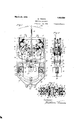
- Figure 1 is a front elevation of sulicient of a weighing apparatus constructed in accoi-dance with the invention as is necessary to an understanding of the invention, the resistant and indicating mechanism being shewn in the no-load position.
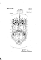
- Figure 2 is an end elevation7 partly in section, of a portion of the mechanism seen in Figure l.
- Figure 3 is a sectional plan view illustrating the relative disposition of the several cam-like members and Figure t is a similar' view to Figure 1 shewing the resistant and indicating mechanism in the full load position.
- the mechanism shewn in the drawings is ⁇ adapted for employment with weighing apparatus of lrnown kind wherein the load is applied to a platform supported on a lever system having connection through a draw bar with the indicating mechanism and those portions of the weighing apparatus which are not necessary to an understanding of the invention are omitted from the drawings.
- suspension cams Two pairs of oppositely disposed camlilre members 5, hereinafter to be rreferred to as the suspension cams, are secured adjacent the lower ends of their peripheries to the lower ends of ieXible ribbons or bands 6, which, at their upper ends, are anchored to a housing 7 within which the mechanism as a whole is disposed.
- a second pair ot segmental cam-like members 9, hereinafter to be referred to as the resistant cams, to the upper ends of the peripl eries whereof are secured the ends oi a pair of )flexible ribbons or bands 10.
- the lower ends ont the flexible ribbons or bands 10 are secured between clamps 11 formed integral with and projecting upwardly from a horizontally disposed bar 12.
- This' bar 12 is provided adjacent the ends thereof with pins 13 which engage within cylindrical recesses 14a formed in a pendulous resistant member letsaid 'pins 13 having coil springs l5 concentrically disposed about the lower portion thereof.
- coil springs 15 are located within enlarged portions of the recesses 1a and abut at ltheir upper ends shoulders termed in the said enlarged portions, the lower ends of the springs abutting the heads oi screws 16.
- the pins 13 and screws 16 are capable of a vertical sliding motion within the recess 14a against the resistance ot the coil springs 15.
- the coil springs 15 serve as shock absorbers and prevent the transmission of violent stresses to the flexible ribbons or bands 10.
- the peripheries of the resistant cams 9 and ot the load cams 17 are eccentrically disposed relative to the peripheries oi' the pairs ot' suspension cams 5 which are concentric with the respective axes of each set of cams.
- each pair oi suspension cams 5 is v.formed on its inner side with a pair ot bosses 5a each or' which has formed therein a tapped recess within which engages a screw 22 the shanks ot the said screws 22 being inclined towards one another so thatl the noses thereof impinge on opposite sides of projections 9 secured to each ot the resistant cams 9.
- the hubs ot the resistant cams 9 are loosely mounted on axially disposed spindles 23 to which the pairs of suspension cams 5 are secured and hence it will Vbe seen that by suitable manipulation oi: the screws 22 adjustment oiI the resistant cams 9 relative to ⁇ the suspension cams 5 can be edected.
- the ends of the axially disposed spindles 23 are pivotally connected to the arms oi' a pair ci' depending U-shaped links 24 which, in turn7 are pivotally connected with a pair of cross bars 25.
- rlhese cross-bars 25 have pivotal connection with a bracket 2G to which is anchored a rack bar 27 adapted to mesh with a pinion 28 fixed on a spindle 29 mounted in ball bearings 30 carried by the housing 7.
- Fixed upon each end ot' the spindle 29 is an indicating pointer 31 said pointers being adapted to register with graduated circular charts 32 in known manner.
- the lower end ot the rack bar 2? is located within a recess 14" formed in the body of the resistant member 14.
- the rack 2T is maintained in mesh with the pinion 28 by means of a guide roller 83 which bears on the rear edge of the rack bar in accordance with common practice.
- rl ⁇ heeccentrically disposed pair of cams 9 and 17 are initially adjusted so that the suspension ribbons or bands 10 and 18 respectively are outwardly inclined when the mechanism is in the 11o-load position with the result that when a load yis applied the eccentric displacement of the cam-like members 9 entails only a relatively small increase in the effective length of the flexible bands lim or ribbons 10 as they unwind from the peripheries of the cams 9 upon the bodily upward movement of the whole of the cams which movement obtains when the suspension cams 5 roll up the suspension bands (ik on the application of a load.
- thesprings 15 act as shock absorbers andr prevent the transmission of sudden shocks to the flexible ribbons or bands 10 wherebyv it'ractme, due to the sudden'application or removal of a load from the weighing platform, is avoided.
- a weighing apparatus constructed as hereinbeiiorc described isfound in practice to be more eflicient and accurate than weighing apparatus of this kind hereinbefore in use.
- An indicating and resistant mechanism for use in connection with weighing apparatus comprising a housing, two pairs of cam-like suspension members disposed on opposite sides of the longitudinal axis of said housing, pairs of iiexible ribbons secured at their upper ends to said housing and at their lower ends to the peripheries of the cam-like suspension members, a resistant carrying cam-like member fixed relatively to each pair of cam-like suspension members and having its periphery eccentrically disposed relatively to the peripheries of the cam-like suspension members, a pendulous resistant, a pair of iexible ribbons anchored at their upper ends to the periphery of the resistant carrying cam-like members and at their lower end to said pendulous resistant, a load carrying cam-like member secured relatively to each pair of cam-like suspension members and having its periphery eccentrically disposed relative to the peripheries of the cam-like suspension members, each set of cam-like members being co-axially disposed and arranged on the same side of the vertical plane passing through the common axes, flexible
- a weight indicating and resistant mechanism for use in connection with weighing apparatus comprising a housing, a plurality of cam-like members, a plurality of ilexible ribbons secured at their upper ends to said housing and at their lower ends to the peripheries of said cam-like suspension members, a pair of resistant carrying cam like members fixed relatively to the cam-like suspension members and having their peripheries eccentrically disposed relatively to the peripheries of the cam-like suspension members, a pendulous resistant, a pair of flexible ribbons anchored at their upper ends to the peripheries of the resistant cam-like members and at their lower ends to said pendulous resistant, a pair of load carrying cani-like members iixed relatively to the suspension and resistant carrying cam-like members and having the peripheries thereof eccentrically disposed relatively to t-he peripheries oi the cam-like suspension members, flexible ribbons anchored at their upper ends to the peripheries of said load carrying cam-like members, means connected lo the lower ends of said last mentioned ribbon
- An indicating and resist-ant mechanism or use in connection with weighing apparatus comprising a housing, two pairs of cam-like members disposed on opposite sides of the longitudinal axis of said housing, pairs of flexible ribbons secured at their upper ends to said housing and at their lower ends to the peripheries of the cam-like suspension members, a.
- resistant carrying lll cani-like member fixed relatively to each pair olf suspension carrying cam-like members, and having its periphery eccentrically disposed relatively to the periplieries of the cam-lilre suspension members, a pendulous resistant, a pair of flexible ribbons anchored at their upper ends to the periphery of the resistant carrying ⁇ cam-like members and at their lower ends to said pendulous resistant, a load carryingl cam-like member secured relatively to each pair of cam-like suspension members and having its periphery eccenti'ically disposed relative to the periphery oit the cam-like suspension members each set ot camdilie men'ibers being coaxially disposed.
- ilenible ribbons connected at their upper ends to the load carrying cam-like members, means connected to the lower ends of said ribbons for transinit'tingg, ⁇ the pull of the load to said ribbons, an indicating, mechaiiism, a pair of spindles cci-axially arranged relative to each oi the cam-like members, a linkage pivotally suspended from said spindles, a rack bar pivotally supported from said linkage, a weight indicator, a pinion secured relatively to said weight indicator and adapted to mesh with and be actuated by said rack bar.
- li. weight indicating ⁇ and resistant mechanism for use in connection with weighing apparatus, comprising; a housing, a plurality of cam-like suspension members, a 'plurality of liexible ribbons secured at their upper ends to said housing and at their lower ends to the peripheries ot the said cam-like suspension members, a pair of resistant carrying, ⁇ cam-like members lined relativcly to the canrlilre suspension members and having, ⁇ their peiipheries eccentrically disposed relatively to the peripheries of the cam-like suspension members; a pendulous re '.stant, a pair oit 'flexible ribbons anchored at their upper ends to the peripheries ot the said resistant cam-like members and at their lower ends to said pendulous resistant, a pair oit load carrying cam-lille members fixed relatively to said suspension and resistant carrying' cam-like members, flexibleribbons anchored at their upper end to the peripheries of said load carrying cam-like members means connected to the lower
- a weight indicating and resistant mechanism for use in connection with Weighing apparatus comprising a housing, a plurality ot cam-like suspension members, a plurality ot flexible ribbons secured at their upper ends to said housing, and at their lower ends to the peripheries of the camlikesuspension members, a pair of resistant carrying ⁇ cam-like members lixed relatively to* the cam-like suspension members and having their peripheries eccentrically disposed relatively to the peripheries ot the cam-like suspension members, a pair of flex* ible ribbons anchored at their upper ends to the peripheries of the said cam-like members, a bar anchored to the other ends of said ribbons, spindles connected to and depending,- from the said bar, a pendulous resistant, apertures formed in said resistant, coil spring
Landscapes
- Physics & Mathematics (AREA)
- General Physics & Mathematics (AREA)
- Transmission Devices (AREA)
Description
March 20, 1928. p 1,663,509
w. nMsoN WEIGHING vAPPARATUS Filed Nov. 22, 192e 2 sheets-snee: 1
f7 A A f7 Q Q f gf .A k D 6* 21' 2l //6 22 22 l' 25 25 /4'1/ 4s. (4 tl *.9 Cif* fzyenorf f March 2o,A 1928. 1,663,509
W. TIMSON WEIGHING APPARATUS Filed Nov. 22, 1926 2 Sheets-Sheet 2 Patented Mar. 20, 1928.
UNITED `STATES PATENT OFFICE.
WILLIAM TIMSON, F BIRMINGHAM, ENGLAND, ASSIGNOR T0 W. & T. AVERY, LIMITED,
` 0F BIRMINGHAM, ENGLAND.
WEIGHING APPARATUS.
Application filed November 22, 1926, Seria] No. 150,102, and in Great Britain May 19, 1926.
This invention has reference to improvements in or relating to weighing apparatus, and relates particularly to weighing apparatus of the kind wherein the weighing resista ant is suspended by means of flexible ribbons from a pair of cam-like members which are fixed relatively to and act in conjunction with additional cam-like members which are suspended by means of flexible lo ribbons from a housing said additional camlike members being adapted, upon the application of a load to the weighing apparatus, to roll bodily up the suspension ribbons the verticalv displacement of the cam-like 16 members thus obtained being caused to effect the actuation of an indicating mechamsm whereby an indication of the measure of the load applied may be obtained.
In weighing apparatus of the aforesaid kind,
20 it has heretofore been proposed to employ a single pendulous resistant freely suspen ed by means of flexible ribbons from a pair o cam-like members which are co-axial with but oppositely disposed relative to two additional sets of cam-like members. To one set of these additional cam-like members the pull of the load is transmitted through flexible ribbons said set of cam-like members being eccentrically disposed relative to the F-U common axes. The other additional set of cam-like members are concentrically disposed relative to the common axes and are .secured to the lower ends of flexible ribbons which are attached at their upper ends to a fixed housing the said last-mentioned set of cam-like members being adapted to roll up the lixed suspension ribbons or bands upon the application of a load to the weighing apparatus. The vertical displacement of the cam-like members is transmitted to a rack which meshes with a pinion mounted on a spindle carrying an indicating pointer or pointers adapted to register with a graduated chart or charts whereby an indication of the measure of the load can be obtained.
With weighing apparatus of the aforesaid kind it is found in practice that by reason of the opposite disposition of the resistant carrying cam-like members relative to the suspension and load cam-like members the movement of the resistant necessary to counterbalance the load is relatively large thereby tending to undesirable oscillation of the pendulous resistant and a consequential imrpossibility of fracture of the said ribbons should a, load be removed from the scale suddenly.
The present invention has for its object the provision of an improved weighing apparatus of the kind herein referred to which y is-ellicient in operation and simple in construction and wherein the aforesaid disadvantages are eliminated.
The invention consists of an improved weighing apparatus of the kind hereinbefore referred to wherein a single pendulous resistant is adapted to depend below and be suspended from a plurality of co-axial camlike members by means of flexible ribbons characterized in that the said cam-like members vare grouped on the same side of the vertical planes passing through the respective axes, the peripheries of the resistant carrying cam-like members and of the camlike members to which the load is applied being eccentrically disposed relative to the common axes, the cam-like members co-operating with the suspension ribbons being concentrically disposed relative to the common axes the eccentric displacement ot the resistant carrying caIn-like members and of the load transmitting cam-like membersentailing a differential motion between the several sets of cam-like members which results in the reduction of the degree of movement imparted to the resistant, the Said cam-like members being connected to the rack for operating the weight indicating mechanism through a pivotal linkage which allows of the free operation of the rack in a true vertical plane thereby permitting of the employment of a weight indicating charthaving equal graduations for equal increments of weight.
The invention will now be described with particular reference to the accompanying sheet of drawings wherein Figure 1 is a front elevation of sulicient of a weighing apparatus constructed in accoi-dance with the invention as is necessary to an understanding of the invention, the resistant and indicating mechanism being shewn in the no-load position.
Figure 2 is an end elevation7 partly in section, of a portion of the mechanism seen in Figure l.
Figure 3 is a sectional plan view illustrating the relative disposition of the several cam-like members and Figure t is a similar' view to Figure 1 shewing the resistant and indicating mechanism in the full load position.
The mechanism shewn in the drawings is `adapted for employment with weighing apparatus of lrnown kind wherein the load is applied to a platform supported on a lever system having connection through a draw bar with the indicating mechanism and those portions of the weighing apparatus which are not necessary to an understanding of the invention are omitted from the drawings.
Two pairs of oppositely disposed camlilre members 5, hereinafter to be rreferred to as the suspension cams, are secured adjacent the lower ends of their peripheries to the lower ends of ieXible ribbons or bands 6, which, at their upper ends, are anchored to a housing 7 within which the mechanism as a whole is disposed.
Cri-axially mounted relative to the suspension cams and fixed relative thereto are a second pair ot segmental cam-like members 9, hereinafter to be referred to as the resistant cams, to the upper ends of the peripl eries whereof are secured the ends oi a pair of )flexible ribbons or bands 10. The lower ends ont the flexible ribbons or bands 10 are secured between clamps 11 formed integral with and projecting upwardly from a horizontally disposed bar 12. This' bar 12 is provided adjacent the ends thereof with pins 13 which engage within cylindrical recesses 14a formed in a pendulous resistant member letsaid 'pins 13 having coil springs l5 concentrically disposed about the lower portion thereof. rlfhe said coil springs 15 are located within enlarged portions of the recesses 1a and abut at ltheir upper ends shoulders termed in the said enlarged portions, the lower ends of the springs abutting the heads oi screws 16. The pins 13 and screws 16 are capable of a vertical sliding motion within the recess 14a against the resistance ot the coil springs 15. The coil springs 15 serve as shock absorbers and prevent the transmission of violent stresses to the flexible ribbons or bands 10.
(lo-axial with the cam members 5 and 9 are provided a third pair or segmental camlilre members 17 hereinafter to be referred to as the load cams to the upper ends ot the peripheries whereof are secured the upper ends ot a further pair of flexible bands or nceasoe -ant mechanism.
The peripheries of the resistant cams 9 and ot the load cams 17 are eccentrically disposed relative to the peripheries oi' the pairs ot' suspension cams 5 which are concentric with the respective axes of each set of cams.
The ends of the axially disposed spindles 23 are pivotally connected to the arms oi' a pair ci' depending U-shaped links 24 which, in turn7 are pivotally connected with a pair of cross bars 25. rlhese cross-bars 25 have pivotal connection with a bracket 2G to which is anchored a rack bar 27 adapted to mesh with a pinion 28 fixed on a spindle 29 mounted in ball bearings 30 carried by the housing 7. Fixed upon each end ot' the spindle 29 is an indicating pointer 31 said pointers being adapted to register with graduated circular charts 32 in known manner. The lower end ot the rack bar 2? is located within a recess 14" formed in the body of the resistant member 14. The rack 2T is maintained in mesh with the pinion 28 by means of a guide roller 83 which bears on the rear edge of the rack bar in accordance with common practice. y
rl`heeccentrically disposed pair of cams 9 and 17 are initially adjusted so that the suspension ribbons or bands 10 and 18 respectively are outwardly inclined when the mechanism is in the 11o-load position with the result that when a load yis applied the eccentric displacement of the cam-like members 9 entails only a relatively small increase in the effective length of the flexible bands lim or ribbons 10 as they unwind from the peripheries of the cams 9 upon the bodily upward movement of the whole of the cams which movement obtains when the suspension cams 5 roll up the suspension bands (ik on the application of a load. This small increase in the effective length of the suspension bands or ribbons 10 only involves a small movement of the pendulous resistant 14 relative to the degree oi' movement given to the rack bar 27 which partakes of the whole of the vertical displacement occasioned by the suspension cams 5 rolling up the suspension loads (i` on the application of a load.
By reason of the small movement of the resistant 14C the tendency to oscillation of the said resistant is lessened and the strain on the ribbons or bands which would be accasioned by the sudden removal of a load is minimized. In addition, the eccentric setting of the cams 17 results in the pull of the load eii'ecting a relatively large motion of the said cams 17 thus augmenting the degree of upward movement of the cams as a whole and increasing the motion of the rack 27.
The inter-connection of the sets of cams by the flexible linkage constituted by the links 24 and cross bar 25 permits of the outward displacement of the cams as a whole due to the eccentric displacement of the pairs or ams 9 and 17 wit-hout thisoutward displacement beingcommunicated to t-he rack bar 27 and hence the said bar can reci rocate in a true vertical plane thereby ena ling a chart having equal graduations for equal increments of load to be employed.
Furthermore, by reason of the .bar 12 having a resilient connection with a resistant 14 thesprings 15 act as shock absorbers andr prevent the transmission of sudden shocks to the flexible ribbons or bands 10 wherebyv it'ractme, due to the sudden'application or removal of a load from the weighing platform, is avoided.
A weighing apparatus constructed as hereinbeiiorc described isfound in practice to be more eflicient and accurate than weighing apparatus of this kind hereinbefore in use.
I claim.
1. An indicating and resistant mechanism for use in connection with weighing apparatus comprising a housing, two pairs of cam-like suspension members disposed on opposite sides of the longitudinal axis of said housing, pairs of iiexible ribbons secured at their upper ends to said housing and at their lower ends to the peripheries of the cam-like suspension members, a resistant carrying cam-like member fixed relatively to each pair of cam-like suspension members and having its periphery eccentrically disposed relatively to the peripheries of the cam-like suspension members, a pendulous resistant, a pair of iexible ribbons anchored at their upper ends to the periphery of the resistant carrying cam-like members and at their lower end to said pendulous resistant, a load carrying cam-like member secured relatively to each pair of cam-like suspension members and having its periphery eccentrically disposed relative to the peripheries of the cam-like suspension members, each set of cam-like members being co-axially disposed and arranged on the same side of the vertical plane passing through the common axes, flexible ribbons connected at their upper ends to the load carrying cam-like members, means connected to the lower ends of said last mentioned ribbons for transmitting the pull of the load to said ribbons, an indicating mechanism and means connected with said cam-like members for actuating the said indicating mechanism. ,u
2. A weight indicating and resistant mechanism for use in connection with weighing apparatus comprising a housing, a plurality of cam-like members, a plurality of ilexible ribbons secured at their upper ends to said housing and at their lower ends to the peripheries of said cam-like suspension members, a pair of resistant carrying cam like members fixed relatively to the cam-like suspension members and having their peripheries eccentrically disposed relatively to the peripheries of the cam-like suspension members, a pendulous resistant, a pair of flexible ribbons anchored at their upper ends to the peripheries of the resistant cam-like members and at their lower ends to said pendulous resistant, a pair of load carrying cani-like members iixed relatively to the suspension and resistant carrying cam-like members and having the peripheries thereof eccentrically disposed relatively to t-he peripheries oi the cam-like suspension members, flexible ribbons anchored at their upper ends to the peripheries of said load carrying cam-like members, means connected lo the lower ends of said last mentioned ribbons for transmitting the pull of the load to said ribbons, an indicating mechanism, a pair of spindles co-axially arranged relatively to they cam-like members, a linkage pivotally suspended from said spindles, a rack bar pivotally supported from said linkage, a weight indicator and a pinion secured relatively to said weight indicator and adapted to mesh with and be actuated by said rack bar.
3. An indicating and resist-ant mechanism or use in connection with weighing apparatus comprising a housing, two pairs of cam-like members disposed on opposite sides of the longitudinal axis of said housing, pairs of flexible ribbons secured at their upper ends to said housing and at their lower ends to the peripheries of the cam-like suspension members, a. resistant carrying lll cani-like member fixed relatively to each pair olf suspension carrying cam-like members, and having its periphery eccentrically disposed relatively to the periplieries of the cam-lilre suspension members, a pendulous resistant, a pair of flexible ribbons anchored at their upper ends to the periphery of the resistant carrying` cam-like members and at their lower ends to said pendulous resistant, a load carryingl cam-like member secured relatively to each pair of cam-like suspension members and having its periphery eccenti'ically disposed relative to the periphery oit the cam-like suspension members each set ot camdilie men'ibers being coaxially disposed. and arranged on the same side of the vertical plane passing through the common axes, ilenible ribbons connected at their upper ends to the load carrying cam-like members, means connected to the lower ends of said ribbons for transinit'tingg,` the pull of the load to said ribbons, an indicating, mechaiiism, a pair of spindles cci-axially arranged relative to each oi the cam-like members, a linkage pivotally suspended from said spindles, a rack bar pivotally supported from said linkage, a weight indicator, a pinion secured relatively to said weight indicator and adapted to mesh with and be actuated by said rack bar.
li. weight indicating` and resistant mechanism, for use in connection with weighing apparatus, comprising; a housing, a plurality of cam-like suspension members, a 'plurality of liexible ribbons secured at their upper ends to said housing and at their lower ends to the peripheries ot the said cam-like suspension members, a pair of resistant carrying,` cam-like members lined relativcly to the canrlilre suspension members and having,` their peiipheries eccentrically disposed relatively to the peripheries of the cam-like suspension members; a pendulous re '.stant, a pair oit 'flexible ribbons anchored at their upper ends to the peripheries ot the said resistant cam-like members and at their lower ends to said pendulous resistant, a pair oit load carrying cam-lille members fixed relatively to said suspension and resistant carrying' cam-like members, flexibleribbons anchored at their upper end to the peripheries of said load carrying cam-like members means connected to the lower ends of said last mentioned ribbons for transmitting the pull of the load to said flexible ribbons, an
indicating,` mechanism, means connected with said cam-like members tor actuating the said indicating mechanism, and means for absorbingJ shock between the pendulous resistant and the flexible ribbons from which it is suspendedc 5. A weight indicating and resistant mechanism for use in connection with Weighing apparatus, comprising a housing, a plurality ot cam-like suspension members, a plurality ot flexible ribbons secured at their upper ends to said housing, and at their lower ends to the peripheries of the camlikesuspension members, a pair of resistant carrying` cam-like members lixed relatively to* the cam-like suspension members and having their peripheries eccentrically disposed relatively to the peripheries ot the cam-like suspension members, a pair of flex* ible ribbons anchored at their upper ends to the peripheries of the said cam-like members, a bar anchored to the other ends of said ribbons, spindles connected to and depending,- from the said bar, a pendulous resistant, apertures formed in said resistant, coil springs located within said apertures, heads lined on the lower ends of said spindles and adapted to abut the lower ends of the coil springs said springs constituting a shock absorption means between the resistant and the flexible suspension ribbons therefor, a pair of load-carrying cam-like members iixed relatively to the suspension and resistant carrying cam-like members, flexible ribbons anchored at their upper ends to the peripheries of said load carrying camlilre members, means connected to the lower ends otk said last mentioned ribbons for transmitting the pull of the load to said iiexible ribbons, an. indicatingmechanism, and means connected with said cam-like members 'for actuating the said,indicatingr mechanism.
ln testimony whereof, I have signed my name to this specification.
WILLIAM TIMSON.
est
Applications Claiming Priority (1)
| Application Number | Priority Date | Filing Date | Title |
|---|---|---|---|
| GB1663509X | 1926-05-19 |
Publications (1)
| Publication Number | Publication Date |
|---|---|
| US1663509A true US1663509A (en) | 1928-03-20 |
Family
ID=10887910
Family Applications (1)
| Application Number | Title | Priority Date | Filing Date |
|---|---|---|---|
| US150102A Expired - Lifetime US1663509A (en) | 1926-05-19 | 1926-11-22 | Weighing apparatus |
Country Status (1)
| Country | Link |
|---|---|
| US (1) | US1663509A (en) |
-
1926
- 1926-11-22 US US150102A patent/US1663509A/en not_active Expired - Lifetime
Similar Documents
| Publication | Publication Date | Title |
|---|---|---|
| US1663509A (en) | Weighing apparatus | |
| US4343196A (en) | Mass and force meter | |
| US1159416A (en) | Weighing-scale. | |
| US2395784A (en) | Weighing apparatus | |
| US1949855A (en) | Weighing device | |
| US2084623A (en) | Fluid pressure gauge | |
| US2045974A (en) | Scale | |
| US2315789A (en) | Automatic dial scale | |
| US1659389A (en) | Scale | |
| US2659594A (en) | Translating assembly for beam-type weighing scale | |
| US1869357A (en) | Weighing-scale | |
| US1875955A (en) | taylor | |
| US2849223A (en) | Adjustment device for weighing scales | |
| US1550125A (en) | Indicating mechanism for pendulous weighing scales | |
| US1880651A (en) | Weighing scale | |
| US2306197A (en) | Automatic weighing and indicating mechanism | |
| US3081640A (en) | Movement multiplying mechanism | |
| US1788020A (en) | Scale | |
| US1768480A (en) | of toledo | |
| US2355293A (en) | Weighing scale | |
| US111733A (en) | Improvement in weighing-scales | |
| US2565970A (en) | Tension measuring instrument | |
| US1746251A (en) | Scale | |
| US1351080A (en) | Automatic weighing-scale | |
| US1848584A (en) | of soho foundry |