US1663508A - Coin-freed delivery mechanism - Google Patents
Coin-freed delivery mechanism Download PDFInfo
- Publication number
- US1663508A US1663508A US95743A US9574326A US1663508A US 1663508 A US1663508 A US 1663508A US 95743 A US95743 A US 95743A US 9574326 A US9574326 A US 9574326A US 1663508 A US1663508 A US 1663508A
- Authority
- US
- United States
- Prior art keywords
- coin
- lever
- escapement
- wheel
- delivery mechanism
- Prior art date
- Legal status (The legal status is an assumption and is not a legal conclusion. Google has not performed a legal analysis and makes no representation as to the accuracy of the status listed.)
- Expired - Lifetime
Links
- 230000037431 insertion Effects 0.000 description 8
- 238000003780 insertion Methods 0.000 description 8
- 230000000994 depressogenic effect Effects 0.000 description 2
- 241000557626 Corvus corax Species 0.000 description 1
- 235000019504 cigarettes Nutrition 0.000 description 1
Images

Classifications
-
- G—PHYSICS
- G07—CHECKING-DEVICES
- G07F—COIN-FREED OR LIKE APPARATUS
- G07F11/00—Coin-freed apparatus for dispensing, or the like, discrete articles
- G07F11/02—Coin-freed apparatus for dispensing, or the like, discrete articles from non-movable magazines
- G07F11/04—Coin-freed apparatus for dispensing, or the like, discrete articles from non-movable magazines in which magazines the articles are stored one vertically above the other
- G07F11/14—Coin-freed apparatus for dispensing, or the like, discrete articles from non-movable magazines in which magazines the articles are stored one vertically above the other with means for raising the stack of articles to permit delivery of the topmost
Definitions
- This invention hasreference to improvements in or connected with coin freed delivery mechanism and relates particularly,
- vvherein'the packages or articles to be delivered ⁇ are alternately arranged and supported in a column, the lowermost package restingon a plurality ofpins projecting from the ends of rods adapted to be rotated through an arc of 90 degrees at a time' for the purpose of releasing a packet Vthe rotation of the said rods being effected through mechanism set in operation by the insertion of a coin.
- the present invention has for its object the provision of mechanism for eifecting the rotation oi the supporting means 'and for eii'ecting the operation thereof upon the insertion of a coin.
- the invention consists of an improved coin freed delivery mechanism of the kind rerovision of a coiled springfor effecting tie rotation of the said supporting means, the requisite m0- tion eifected by the said coiled spring being r'governed by an escapement mechanism adapted to be controlled through a trip ⁇ mechanism actuated by the coin.
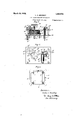
- the invention will Inow be described with particular reference to the accompanying sheet of dravvings,'vvherein:- Figure lis ,a front elevation vof a, coin yfreed mechanism in accordance with the inventionv for delivering packetsof cigarettes.
- Figure 2 is a side elevation of Fi ure 1.
- Figure 3 is a vertical section of t eupper portion of the mechanismseen inu Figuresl'. v W
- Figure 4 is a plan of Figure 1, andf y"Figure 5jis a sectional plan on the line 5-5 of Figure 1.
- i -The-packets 6 are arranged alternately in v a column and supported by means of pins 7 which project equally oneither side of the lower ends oiffeed rods 8.
- These rods 8 are 'rotatably mounted at their upper and lower ends within bearings formed in plates 9 and 10 respectivelyl said plates 9 4and 10 being maintained apart by means of a distance ⁇ piece 11 secured to eachof the said plates 9.and 10.
- the plate 9 is vadapted to embrace a pairl of oppositely dise Vplate 14 which constitutes the bottom housing plate for the actuating mechanism.
- a common spur Wheel 17' secured to a casing 18 adapted to contain a clock spring 19.
- One" end of the clock spring 19 is anchored to ashaft 20 rotatably mounted in the bottom plate 14 andin a plate 21 forming the top plate ofthe housing for the actuating mechanism, thespring 19 being adapted to be tensioned by means-of rotation of the vshaft 20 by a knob 22 secured thereon.
- Thepinions 16 are also provided with upwardly projecting bosses 16a the upper ends whereofy are rotatably mounted in bearings formed-fin :the top housing plate 21. Secured'to one of these bosses 16'n1 is an escapement Wheel 26 carrying four stops 26L Which Vare' arranged at 90 degrees apart the escapementwh'eel 26 being disposed above the top housing plate21.
- this trip lever 32 is provided with a cranked Section 32" which is adapted. to project withinthe coin chute 35 and to be depressed by the coin during its tall a spring 36 anchored at one end to the trip lever 32 and at the otherend to a pin 37 project-ing Yfrom the bracket 38 being provided for returning the trip lever 32 to its nornial position.
- the escapement lever 27V is connected to the piston rod 38 ot a double acting dashpot 39 tor regularizing the action of the mechanism.
- a shutter il Secured at the lower end of a rod ll() is a shutter il adapted to close the coin slot 35a when the word empty appears on the drum 23 suitable gearing .being provided to ensure synchrony between the drum 28 and the shutter al.
- the escapenient lever 27 is also provided with a pin 27C adapted to have connection with a cranked arm vll2 adapted to actuate a counting mechanism 43 said counting mechanism beingsecured to the bot-tom housing plate by means ot a bracket 44- the indications oi the counting ymechanism :being visible through a window formed in the case or housing within which the mechanism is located.
- the operation of the mechanism is :as vfollows: Upon the insertion of a coin in the slot the said coin traverses the chute 35 and in its passage strikes the cranked arm 32h oit the trip lever32 which projects within the said chute. This lever 32 is depressed by vthe weight ot the coin and thereupon raises the other arm whereby the arm 3la of the rod 3l is ⁇ treed tromengagement with the stop 82 on the :upper jaw ot .the trip lever 32 and allows the said-arm 3la tomove in an anti-clockwise direction.
- a coin treed delivery mechanism constructed as hereinbefore .described admits of the whole of the mechanism .being enclosed :ing a dispensing mea-ns, ayspur wheelradapted to be driven from said shaft, an escapement wheel adapted to be driven yfrom said spurv wheel, stops .arranged kat .90 :degrees apart on said escapement wheel, an escapement Jever adapted Ito cio-.operate '.Withsaid escapement wheel for Aeti'ecting the release ot the said lever subsequent :to 'the insertion ot a coin .and ,trip ⁇ mechanism Iadapted for actuation :by the coin for controlling the operation of said lever.
- ,2A rcoin 'feed delivery mechanism comprising 4a spring .operated ⁇ shaft .for actuatinga dispensing means, a spur wheel adapted to be driven .trom-said shaft, ⁇ an escapement wheel adapted Lto befdriven from ysaid spur wheel, stops arranged at degrees apart -on Said escapement Wheel,an escapelment lever adapted to co-operate with said 'escapement wheel for effecting the release of said lever subsequent tothe insertion of a coin, a coin-chute, a trip 'lever an arm whereof is disposed within said coinchute,
- a coin freed delivery mechanism comprising a spring operated shaft for actuating a dispensing means, a spur wheel, adapted to be driven from said shaft, an escapement wheel adapted to be driven from said spur wheel, stops arranged at 90 degrees apart on said escapeinent Wheel, an escapement lever adapted to co-operate With said escapeinent wheel, a coin chute, a trip lever an arm whereof is disposed in the coin chute and in the path of the falling coin, a stop on the other arm of said trip lever, and a rotatably mounted rodV in operative connection at its upper end with the escapement lever and at its lower end with the stop on the trip lever the rotation of said rod being controlled by the trip lever for freeing the escapement lever upon the insertion of a coin.
- a coin freed delivery mechanism comprising a spring operated shaft for actuating a dispensing means, a spur wheel adapted to be driven from said shaft, an esca-pement wheel adapted to be driven from said spur wheel, stops arranged at 90 degrees apart on said eseapementwheel, an escapement lever adapted to co-operate Withsa-id escapement wheel, a coin chute, a trip lever one means for returning the pin andquadrantalk member to their normal positions.
- coin freed delivery mechanism comprising a spring operated shaft for actuating a dispensing means, a spur wheel adapted to be driven from said shaft, an escapement wheel adapted to be driven from said spur wheel, stops arranged at 90 degrees apart on said escapement wheel, an escapement lever adapted to co-operate With said esca-pement wheel, a coin chute, a trip lever an arm whereof is disposed Within said coin chute, Ymeans connected with said trip lever for releasing the escapement lever upon the insertion of a. coin, and means for denoting the number of packets remaining or extracted from the machine.
Landscapes
- Physics & Mathematics (AREA)
- General Physics & Mathematics (AREA)
- Control Of Vending Devices And Auxiliary Devices For Vending Devices (AREA)
Description
March 20, 1928. 1,663,508
. L. C. BRADLEY com FREED DELIVERY MEcHANIsM Filed March 18. 1926 2 Sheets-Sheet l Fay] Fig. 28 22 45 w 59 59 47 295 26 le /6 J0 26a] o 3 `20 Z7 f Y' y4'7 2/ Il 27a'l Z7@ /6 /6 42 /6 le@ ,/7\ "5 c ,fg fea y r /6 /6 4 i /4 5 24 .I 2 z5 zum 24 al i 6 5/ I 52 ig 525 52 55 5-- I "-5 55 55 52 I |.il L 7 /o 6 .7 7 6 7 raven/01 eske C. rafley Mlarch 2o, 192s.
1,663,508 L. c. BRADLEY COIN FREED DELIVERY MECHANISM A Filed March 18. 1926 Fay. 5,
2 SheetsSheet 2 In van or f eslie C. ruleg y @my hs torney l Vferred to and comprises the Patented Mar. 20, 1928.
UNITED STATES *PATENT OFFICE.
LESLIE CLIFFORD BRADLEY, 0E BrRMINenaM, ENGLAND, AssIGNoR To W. a fr.
vAVERY, LIMITED, or BIRMINGHAM, ENGLAND. f
' COIN-FREED DELIVERY MEciimNIsM.Y
Application led March 18, 1926, Serial No. 95,743, and in" Great Britain March 23, 1825.
This invention hasreference to improvements in or connected with coin freed delivery mechanism and relates particularly,
to such mechanism vvherein'the packages or articles to be delivered` are alternately arranged and supported in a column, the lowermost package restingon a plurality ofpins projecting from the ends of rods adapted to be rotated through an arc of 90 degrees at a time' for the purpose of releasing a packet Vthe rotation of the said rods being effected through mechanism set in operation by the insertion of a coin. The present invention has for its object the provision of mechanism for eifecting the rotation oi the supporting means 'and for eii'ecting the operation thereof upon the insertion of a coin. n
The invention consists of an improved coin freed delivery mechanism of the kind rerovision of a coiled springfor effecting tie rotation of the said supporting means, the requisite m0- tion eifected by the said coiled spring being r'governed by an escapement mechanism adapted to be controlled through a trip` mechanism actuated by the coin. The invention will Inow be described with particular reference to the accompanying sheet of dravvings,'vvherein:- Figure lis ,a front elevation vof a, coin yfreed mechanism in accordance with the inventionv for delivering packetsof cigarettes. Figure 2 is a side elevation of Fi ure 1. Figure 3 is a vertical section of t eupper portion of the mechanismseen inuFiguresl'. v W
Figure 4 is a plan of Figure 1, andf y"Figure 5jis a sectional plan on the line 5-5 of Figure 1. i -The-packets 6 are arranged alternately in v a column and supported by means of pins 7 which project equally oneither side of the lower ends oiffeed rods 8. These rods 8 are 'rotatably mounted at their upper and lower ends Within bearings formed in plates 9 and 10 respectivelyl said plates 9 4and 10 being maintained apart by means of a distance` piece 11 secured to eachof the said plates 9.and 10. In addition, the plate 9 is vadapted to embrace a pairl of oppositely dise Vplate 14 which constitutes the bottom housing plate for the actuating mechanism.
`a common spur Wheel 17' secured to a casing 18 adapted to contain a clock spring 19. One" end of the clock spring 19 is anchored to ashaft 20 rotatably mounted in the bottom plate 14 andin a plate 21 forming the top plate ofthe housing for the actuating mechanism, thespring 19 being adapted to be tensioned by means-of rotation of the vshaft 20 by a knob 22 secured thereon.
,'Secured to the lower section of the main shaft 20 and rotatable therewith is a cylin- Vsaid numerical markings being observable through a Window disposed at the front of ythe casingor housingvvithin which the apparatusis normally located and serving to denote the number of packets remaining in the machine. Secured totheupper surface of thenplates 9y are four cqui-'distantly 'spacedleaf springs 24 the free ends whereof are adapted to co-operate with a plurality of correspondinglyspaced'angle brackets 25 se curedk to "the undersurface of the bottom housing plate 14 said springs 24 andangle brackets--2`5 cooperating tolsecure the container unit to the actuating mechanism.
\ Adapted-to 4engage With this escapement wheel is a yforked es'capement lever 27 the arms 27a whereof engage with the stops 26l onV the escapement wheel 26 said lever 27 being pivotally mounted on a spindle 28 projecting from the top 'housing plate 21. The lever 27 is pivotally connected at itsother end to a link 29 said link having" at the end "drical 'drum' 23 provided with numerical markings around the periphery" thereof thereof a pin 29b adapted to engage within a notch 30a formed in a quadrant 30 secured at the upper end of a rod 3l which is rotatably mounted in a sleeve 3l" secured to the iousing platesv lat and 2l. The lower end mounted on a pin 33 secured to a bracket carrie-d by a 'Hired rod 34. The other arm ot' this trip lever 32 is provided with a cranked Section 32" which is adapted. to project withinthe coin chute 35 and to be depressed by the coin during its tall a spring 36 anchored at one end to the trip lever 32 and at the otherend to a pin 37 project-ing Yfrom the bracket 38 being provided for returning the trip lever 32 to its nornial position.
The escapement lever 27V is connected to the piston rod 38 ot a double acting dashpot 39 tor regularizing the action of the mechanism.
Secured at the lower end of a rod ll() is a shutter il adapted to close the coin slot 35a when the word empty appears on the drum 23 suitable gearing .being provided to ensure synchrony between the drum 28 and the shutter al.
The escapenient lever 27 is also provided with a pin 27C adapted to have connection with a cranked arm vll2 adapted to actuate a counting mechanism 43 said counting mechanism beingsecured to the bot-tom housing plate by means ot a bracket 44- the indications oi the counting ymechanism :being visible through a window formed in the case or housing within which the mechanism is located.
The operation of the mechanism is :as vfollows: Upon the insertion of a coin in the slot the said coin traverses the chute 35 and in its passage strikes the cranked arm 32h oit the trip lever32 which projects within the said chute. This lever 32 is depressed by vthe weight ot the coin and thereupon raises the other arm whereby the arm 3la of the rod 3l is `treed tromengagement with the stop 82 on the :upper jaw ot .the trip lever 32 and allows the said-arm 3la tomove in an anti-clockwise direction. The rotation ot the .arm 3l however is temporarily arrested by a stop 32C on thelower jawot the trip lever '32, `the initial .motion however thus permitted admits of the partial disengagement ot the pin 29b on the link 29 in connect-ion with the escapeinent lever 27 from within its notch 30a in the quadrant 30. Upon the release ot the coin from kthe chute the trip lever 32 rises and permits of the disengagement ot the arm 3la from the stop 3J on the lower jaw of the-trip lever 32 and admits ot the arm 3l continuing its anticlockwise motion. This continued motion admits ot' the complete disengagement of 4ends .thereof whereby the lowerinost packet G is treed and allowed to tall into the 'delivery chute. Simultaneous with the lpartial release ot the escapement wheel 2G two of .the stops 26 on the said wheel icome into engagement with the forked arms 27El of the .escapement lever 27 .and return the :same to its initial position. rllhe gquadrant :30 and link 29 are also returned totheir initial position `by means et springs vand 46 crespectively .connected therewith, Ia stop if? being` provided to limit the return motion ot' the quadrant 30. The motion of theescapeinent lever 2? is retarded by means vof the dashpot 39 whereby a sufficient period-of time elapses between the successive operations of the trip mechanism to `admit .of the rde-livery of ythe t.
packet without causing any jamming of the several parts of the mechanism.
A coin treed delivery mechanism constructed as hereinbefore .described admits of the whole of the mechanism .being enclosed :ing a dispensing mea-ns, ayspur wheelradapted to be driven from said shaft, an escapement wheel adapted to be driven yfrom said spurv wheel, stops .arranged kat .90 :degrees apart on said escapement wheel, an escapement Jever adapted Ito cio-.operate '.Withsaid escapement wheel for Aeti'ecting the release ot the said lever subsequent :to 'the insertion ot a coin .and ,trip `mechanism Iadapted for actuation :by the coin for controlling the operation of said lever.
,2A rcoin 'feed delivery mechanism .comprising 4a spring .operated `shaft .for actuatinga dispensing means, a spur wheel adapted to be driven .trom-said shaft,` an escapement wheel adapted Lto befdriven from ysaid spur wheel, stops arranged at degrees apart -on Said escapement Wheel,an escapelment lever adapted to co-operate with said 'escapement wheel for effecting the release of said lever subsequent tothe insertion of a coin, a coin-chute, a trip 'lever an arm whereof is disposed within said coinchute,
lll() and means connected with said trip lever for releasing the escapement lever upon the insertion of a coin.
3. A coin freed delivery mechanism comprising a spring operated shaft for actuating a dispensing means, a spur wheel, adapted to be driven from said shaft, an escapement wheel adapted to be driven from said spur wheel, stops arranged at 90 degrees apart on said escapeinent Wheel, an escapement lever adapted to co-operate With said escapeinent wheel, a coin chute, a trip lever an arm whereof is disposed in the coin chute and in the path of the falling coin, a stop on the other arm of said trip lever, and a rotatably mounted rodV in operative connection at its upper end with the escapement lever and at its lower end with the stop on the trip lever the rotation of said rod being controlled by the trip lever for freeing the escapement lever upon the insertion of a coin.
4. A coin freed delivery mechanism comprising a spring operated shaft for actuating a dispensing means, a spur wheel adapted to be driven from said shaft, an esca-pement wheel adapted to be driven from said spur wheel, stops arranged at 90 degrees apart on said eseapementwheel, an escapement lever adapted to co-operate Withsa-id escapement wheel, a coin chute, a trip lever one means for returning the pin andquadrantalk member to their normal positions.
5. coin freed delivery mechanism comprising a spring operated shaft for actuating a dispensing means, a spur wheel adapted to be driven from said shaft, an escapement wheel adapted to be driven from said spur wheel, stops arranged at 90 degrees apart on said escapement wheel, an escapement lever adapted to co-operate With said esca-pement wheel, a coin chute, a trip lever an arm whereof is disposed Within said coin chute, Ymeans connected with said trip lever for releasing the escapement lever upon the insertion of a. coin, and means for denoting the number of packets remaining or extracted from the machine.
In testimony whereof, I have signed my name to this specication.
LESLIE CLIFFORD BRADLEY.
Applications Claiming Priority (1)
| Application Number | Priority Date | Filing Date | Title |
|---|---|---|---|
| GB1663508X | 1925-03-23 |
Publications (1)
| Publication Number | Publication Date |
|---|---|
| US1663508A true US1663508A (en) | 1928-03-20 |
Family
ID=10887909
Family Applications (1)
| Application Number | Title | Priority Date | Filing Date |
|---|---|---|---|
| US95743A Expired - Lifetime US1663508A (en) | 1925-03-23 | 1926-03-18 | Coin-freed delivery mechanism |
Country Status (1)
| Country | Link |
|---|---|
| US (1) | US1663508A (en) |
-
1926
- 1926-03-18 US US95743A patent/US1663508A/en not_active Expired - Lifetime
Similar Documents
| Publication | Publication Date | Title |
|---|---|---|
| US1663508A (en) | Coin-freed delivery mechanism | |
| US2416213A (en) | Parking meter | |
| US2076513A (en) | Check controlled mechanism | |
| US1065029A (en) | Automatic vending-machine. | |
| US3750829A (en) | Article vending machine having bonus dispensing means | |
| US2258308A (en) | Coin-controlled weighing scale | |
| US2088856A (en) | Vending apparatus | |
| US1949541A (en) | Stamp-vending machine | |
| US2328043A (en) | Parking meter | |
| US1786014A (en) | Coin-controlled mechanism | |
| US1488288A (en) | Combined vending and weighing machine | |
| US1986771A (en) | Coin register | |
| US1813299A (en) | Vending machine | |
| US1848626A (en) | Coin controlled vending machine | |
| US2128180A (en) | Coin controlled apparatus for dispensing machines | |
| US1765108A (en) | Vending machine | |
| US1718584A (en) | Registering apparatus | |
| US2002373A (en) | Coin controlled indicating device | |
| US2199330A (en) | Parking meter | |
| US2421857A (en) | Coin chute | |
| US1838993A (en) | Coin controlled weighing scale | |
| US1969069A (en) | Coin controlled mechanism | |
| US1155078A (en) | Coin-operated weighing-scale. | |
| US2139920A (en) | Counting register for coin controlled mechanisms | |
| US1882634A (en) | Check-controlled apparatus for vending machines |