US1663459A - Lasting machine - Google Patents
Lasting machine Download PDFInfo
- Publication number
- US1663459A US1663459A US704502A US70450224A US1663459A US 1663459 A US1663459 A US 1663459A US 704502 A US704502 A US 704502A US 70450224 A US70450224 A US 70450224A US 1663459 A US1663459 A US 1663459A
- Authority
- US
- United States
- Prior art keywords
- jaws
- last
- gripper
- jaw
- margin
- Prior art date
- Legal status (The legal status is an assumption and is not a legal conclusion. Google has not performed a legal analysis and makes no representation as to the accuracy of the status listed.)
- Expired - Lifetime
Links
Images


Classifications
-
- A—HUMAN NECESSITIES
- A43—FOOTWEAR
- A43D—MACHINES, TOOLS, EQUIPMENT OR METHODS FOR MANUFACTURING OR REPAIRING FOOTWEAR
- A43D21/00—Lasting machines
- A43D21/16—Lasting machines with lasting pincers and toe- or heel-embracing wipers
-
- A—HUMAN NECESSITIES
- A43—FOOTWEAR
- A43D—MACHINES, TOOLS, EQUIPMENT OR METHODS FOR MANUFACTURING OR REPAIRING FOOTWEAR
- A43D21/00—Lasting machines
- A43D21/12—Lasting machines with lasting clamps, shoe-shaped clamps, pincers, wipers, stretching straps or the like for forming the toe or heel parts of the last
- A43D21/125—Lasting machines with lasting clamps, shoe-shaped clamps, pincers, wipers, stretching straps or the like for forming the toe or heel parts of the last with a plurality of pincers
-
- A—HUMAN NECESSITIES
- A43—FOOTWEAR
- A43D—MACHINES, TOOLS, EQUIPMENT OR METHODS FOR MANUFACTURING OR REPAIRING FOOTWEAR
- A43D21/00—Lasting machines
- A43D21/18—Lasting machines with lasting pincers and straight-acting wipers, also for forming the shank portions of shoes
Definitions
- This invention relates tov apparatus for lasting footwear, in the broad sense of assembling or ⁇ associating an upper shoe part W1th a 1ast,.and in certain aspects is an improve- 5 ment upon the inventions described and claimed in my applications Serial Nos. ⁇ 582,- 884, 630,796, 703,905 and 11,525, filed August 19, 1922, April 9, 1923, April 3, 1924, and February 25, 1925, respectively.
- f l0 apparatus adapted to stretch ashoe upper or an upper shoe part onto a last and especi-allya heavy, cloth upper, or a; cloth-andleather upper, such as is commonly used for l tennis slices.
- a more specific object is to assemble such an upper and a last in determinate relation, and more particularly by .first accurately positioning them on respective'supporting structures ⁇ held in non-contiguous positions such that they may freely receive and accuratelyposition the work, and' then bringing them into the desired association with each other by a determinate relative lmovement of said structures.
- a further object is to provide improved means, including strong upper-engaging members, for applying the margin of an upperor the like to the sole face -ot a last uponV which it is mounted, or to an'insole associated with the last.
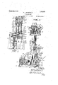
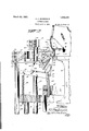
- Fig. 1 is a front elevation of a lasting machine embodying my invention in a preferred form, and the work therein, some of the details being omitted.
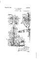
- p Fig. 2 is an end elevation of the same, as 'viewed from the left of Fig. 1.
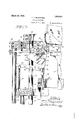
- Fig.- 3 is a fragmentary, vertical section of actuating mec anism, .on line 3-3 of 4o i FSI. 4.
- Fig. 4 is a vertical section, on a large scale, of parts of the actuating mechanism, on line 4-.4 of Fig. 1. i
- Fig. 5 is a horizontal section of the driving clutch mechanism, on line 5-5 of Fig. 4.
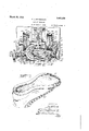
- Fig. 6 is a plan view of the machine, parts being'sectioned on line'G- -of Fig. 1 and lbroken away for clearness of illustration.
- Fig. 7 is a perspective view of the linished Work.
- Fig. 8 is a vertical section of the machine, on 1ine8-8 of Fig. 1, some of the nipper units and other parts being omitted for clearness of illustration. Y
- Fig. 9 is a perspective view of a nipper an early stage of operation
- My chief objectI is to provide improved
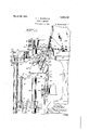
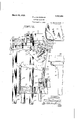
- Flg. 10 1s a fragmentary, vertical section of upper-manipulating instrumentalities at one of the nipper units belng'shown in elevation.
- stationary frame 12 is a set of gripper-units, 75
- three vertically movable, annular frames, 16,17 and 18, surrounding the lastinoposition at diii'er- 90 ent elevations are secured to the tops of respective sets of lifting bars 19, 19, 20, 20 and 21, 21 respectively, and are adapted -to be raised and lowered in timed relatlon for simultaneously actuating the gripper-units throughout a cycle of operations.
- Said lifting bars are slidably mounted in brackets 22, 22 secured to the frame members 10, and are pivotally connected below' to respective eccentric mechanisms comprising respective eccentric collars 23, 24, 2 5.
- each gripperunit is provlded at its elbow wlth a pair of pivot studs such as 26, by which 1t 1s 'ivoted in vertical closed slots such as 27 ormed in the Jforked upper end of a post 28 mounted upon the frame 12 and adapted to be secured in different vertical positions thereon by a set screw 29.
- Each of said carriers has an uprlght jaw-carrying arm 30 and a horizontal actuating arm 31, an intermediate part of the latter being connected with.
- a lost motion link 32 adapted to permit the carrier to tilt toward the lasting position, and also to permlt 1t to rise vertically to the extent permitted by the slots 27 in the post 28, when said frame is in an elevated position.
- the carrier 1s adapted to be so tilted and raised by the force of a compression spring 33 connecting the arm 31 with the frame 16, said spring being mounted upon a spring rod 34 pivoted at 35 to the outer end of the carrier arm 31, extending with a loose fit into an aperture formed in the frame 16, and having such play therein as to permit its necessary angular movement with relation to said frame.
- the lower end portion of the link 32 is likewise loosely mounted in an aperture in the frame 16 andvprovided with a nut 36 below the latter, so that the frame 16 will tilt the several carriers 15 away from lasting position, for the reception of the next upper, when said frame is lowered.
- each jaw carrier 15 is formed as a pair of parallel plates held in spaced relation by suitable spacing members, and each plate has formed thereon at its upper end a corrugated jaw such as 37, the two jaws being adapted to act as one, and jaws 38, mating with the jaws 37, are
- lever 39 consisting of a pair of spaced apart plates straddling the vertical carrier arm 30 and pivoted thereto at 40.
- the lever 39 is formed with an outwardly projecting arm having an arcuate upper face 39a which is concentric with the pivot 26 of the jaw carrier when the jaws 37 38 are in closed relation, so that said jaws may be held closed by a roller 41 mounted upon the upper actuating frame 18, and running upon the arcuate upper face 39EL of lever 39, while the carrier is tilted toward the lasting position, from its upper receiving position.
- a pair of upper-positioning jaws 43, 44 adapte to grip the upper lightly and slide thereon, are mounted between the side plates recaen@ of the vertical 4carrier arm4 30 and between the members of the double jaws 37 and of the double-jaws 38, and are hinged together at 45, the upper jaw being forked at its hub to straddlethe lower jaw 44, and the latter having a rearward extension 46 pivoted at 47 to a crooked lever 48, said lever being pivoted at 49 to the vertical jaw-carrierarm 30.
- the crooked lever 48- is thus adapted to project and retract the jaws 43, 44 past the corrugated jaws 37, 38, the lower jaw, 44, ruiming upon a roller 4()a journaled between the plates of the arm 30, on the pivot piu 40 of the gripper jaws.
- a pull spring 50 connects an intermediate part ot the lever 48 with the vertical carrier arm 30,
- the lever 48 is formed with an arcuate upper face 48a adapted to be engaged by a roller 51 mounted upon the intermediate actuating frame 17, said arcuate face being concentric with the pivot 26 oi the jaw carrier l5 when the sliding jaws 43,A
- a double plate dog 52 has its respective plates pivoted as at 53 to downwartl extensions from the rear arm of the lever 39, said dog having a roller 54 journaled between its plates at its forward end, adapted to run upon the upper face of the jaw 43 for holding the latter closed, and to engage a projection 55 upon said jaw at its hub for swinging the jaw open, and the plates of said dog being formed mid-way of their length with respective upstanding arms, such arms constituting a lever 56 which is connected by a pull spring 57 with a partof the lever 39 adjacent the .latters hub.
- the dog 52 by the force of said spring urging it about its pivot 53, is adapted to bear yieldingly upon the jaw 43 as the jaws 43, 44 are projected and retracted, and also to exert upward force on the lever 39 at its pivot 53 for urging the lever 39 and its jaw 38 toward open position, the dog 52 also bein so disposed that when the jaws 43, 44 reac 1 the limit of their projective movement the roller 54 will engage the-projection 55 of the jaw 43 for swinging the jaw 43 open to receive the shoe upper, as shown in i Fig. 9. y
- the jaws 43, 44 are adapted to be limited in their projective movement by contact of the hub portion of the jaw 43 with the carrier arm 30, as shown'in Fig. 9, and in their opening movement by contact of the roller 54 with the lower jaw 44, and the jaw 38 is adapted to be limited in its opening movement by contact of shoulders such as 59, formed on the side plates of the levers 39, with stop-lugs such as 59, ⁇ formed on the side plates ot' the carrier arm 30.
- the roller 41 which runs upon the lever 39 for closing the jaw 38 is journaled at the end of a spring arm 60, which is adapted ⁇ to yield to compensate for relatively great thickness of the upper where seams occur, and said arm is welded to a bracket 61 screw-bolted to the outer -face ofthe frame 18.
- a set screw 62 threaded through -the frame. 18 bears upon the spring arm 60 and is adapted to be adjusted to vary the force with which the jaws 37, 38 grip the margin of the upper.
- the roller 51 vwhich runs upon the lever 48 for retraeting the upperpositioning jaws 43, 44, is'journaled at the end of a rigid arm 63 pivoted at 64 to a bracket 65 screw-bolted to the outer face of the frame 17.
- a set screw 66 threaded through the frame 17 bears upon the arm 63 and is adapted to be adjusted to determine the position to which the upper positioning jaws are retracted.
- the roller 41 may likewise be lifted clear of its lever 39, as shown in Fig.
- brackets 67, 68 rising from the base 11 outside of the frames 10 is a main drive shaft 69, having secured thereon @ive pinions 70, 71 meshed respectively with large gears 72, 73 formed upon the outer ends of respective segmental-gear drums 74, 75, the latter being secured upon respective shafts 76, 77 journaled in the respective brackets 67, 68 and extending through respective bearings formed on brackets 78, 79
- Said carriage 14 is connected with the forward end of the lever 84 by a two-part connecting rod 86 provided with a turn-buckle 87 for 'varying its effective length.
- the carriage is formed with a base or cross-head 14 slidably mounted between and adapted to be guided by the frames l0, the cross-head when in its-lowcrmost position being adapted to rest upon a cross-brace 88 connecting the framesl 1() and formed with a ccn'tral apelture 88u accomodating the connecting rod 86.
- a. block 89 constituting a lastsupport, and said last support is preferably formed with suitable apertures andiitted upon dowels 99, 9() projecting from the upper face of the last carriage, so that last supports .of different sizes readily may be substitued.
- the last support conforms to the sole face of the last and-is thus adapted to hold snugly against the last an insole 91 interposed between the two, and the last support is of smaller vertical projection than the last, so that the latter overhangs or projects horizontally be- 'yond the last support, with a uniform mar- (lll gin of overhang around the solel face ot' the 'l last, as will readily be understood upon reference to Fig. 12, such overhang permitting the application of the sole margin of an upper to the insole while the work rests upon the 'last support.
- a generally U-shaped jig 92 is. detaehably secured upon a jig-carrier 92, the
- said jig-carrier is provided with a. stud (Figs. 2 and 8) adapted to bear against sultable stop faces formed on one ofthe brackets 94 for holding the jig respectively in horizontal position for receiving the last, and in an over-center position, the stud 95 abutting a projection 96 on the bracket 94, so
- the jig is out of the way for the passage of the base ortio'n or cross-head 14'L of the last-carnage.
- the jig-carrier 92u For automatically swinging the jig-carrier 92u from one to the other of these positions it has secured to the hub of one of' its hinge-arms Ia fork 97 ada ted to receive a stud 98 (Figs. 2 and 8) projecting from the cross-head 14, the two positions of the jlg, as determined by the stud-95, being such that the stud 98 will be received by the fork 97 in both the upward and downward movements of the last-carriage.
- connecting rods- ⁇ adapted on occasion to be adjusted in length to vary the starting and stopping position ot' the trames 17, 18, although when once adjusted their length does not ordinarily rcquire to be changed for operating upon shoes of ditl'erent sizes, the positioning of the gripper units for shoes of different sizes being taken care of by varying the starting or upper-receiving position ol the gripper-tilting frame 16.
- each pair of its supporting bars 19 have secured to their lower ends, in common, a bracket 101 formed with a downwardly extending arm 101a at the rear, to which is pivoted at 102 a pair of parallel, adjusting levers 103, 103.
- a bolt 106 is mounted in apertures in the four levers 103, provided with a -spacer sleeve 106 (Fi 6) between the two innermost levers, an provided at one end with a hand wheel 107 having a threaded hub mounted on the end of the bolt for drawing the levers 103 of each pair 75 nism, to vary the initial positiening of the gripper units for uppers of different sizes.
- the lost motion links 32 which return the gripper units to upper receivingv position after each lasting operation are connected to the actuating carrier arms 31 at points au on the latter relatively close to the carriers pivot 26, as to the carriers positioned about the heeland toe of the work, while the links ⁇ of the gripper units at the instep of the last are connected to the actuating arms 31 at SI5 points on the latter more remote from the pivots 26, as will be clear from a comparison of Fig. 8 with Fi 10 for example, the effect of this being t at when the levers 10:3 z
- the resulting variation of the starting position of the frame 16 does not affect the positioning of the gripper arms 30 at the instep of the last as much 105 as it does that of the gripper arms 30 which are at or near the heel and toe of the last, this being in accordance with the fact that lasts of different sizes do not have soles ot' geometrically similar form, but vary more 110 in outline about the heel and toe portions than they do at the instep'.
- the arrangement described is such that the gripper carriers will be properly positioned for lasts of dili'erent sizes by the simple adjustment 1,15
- the eccentric collars 23, 24, 25 are mounted respectively upon eccentrics 112, 113, 114, (see Fig. 3) said eccentrics of each set, at the respective sides of the machine, being loosely journaled in axially abutted relation upon a shaft 115 mounted in the adjacent bracket 67 or 68 and in the adjacent frame member 10, from which they are spaced by suitable spacing collars 116, 117, 118.
- Said eccentrics are provided with individual driving gears 119, 120, 121 respectively secured on their hubs, and said eccentrics are adapted to be intera right and 80 row in Fig. 4.
- Each of the gears 119, 120, 121, secured to therespective eccentrics, 3, has a tooth omitted therefrom at two diametricall opposite points, as shown at 128, 128 in 4, as to the gear 119, to permit the ear-segments to come into mesh without inding.
- each is a bell-crank pawl lever, 129, 130, or 131, said levers being pivoted upon a common shaft 132, Figs. 2 and 4, each pawl lever being urged into engagement with its gear by a spring such as is shownat 133 in Figs.
- each bell-crank lever extends toward the segmental gear drumand is adapted to be engaged by successive cams, suchA as are shown at 134, 134, (Fig. 4) secured upon the drum adjacent the respectivegear segments, to disengage the pawl levers from their respective gears during the time that the latter are meshed with the gear segments.
- the main drive shaft 69 journaled in the brackets 67, 68 and having the drive pinions 70, 71 secured thereon as above described, is provided with a brake drum 135 and a jawclutch member 136, Figs. 1, 4, and 5, said clutch member being adapted to mate with a jaw-clutch member 137 secured to the hub of a drive pulley 138 which is slidably and rotatably mounted upon the shaft 69 and adapted to bemoved axially, to engage and disengage the clutch, by means of a shipper lever 139 secured upon a shaft 140 journaled in the bracket 67, said shipper lever bein formed with a horizontal arm 141 forme with a brake shoe 142 adapted to engage the brake drum 135 when the clutch 136, 137 is disenga ed.
- a foot lever 143 is secured to the shag: 140 for engaging the clutch, and a sprin 144 connects said foot lever with the brac et 67 for urging the clutch member 137'out of engagement.
- the brake-shoe arm 141 is formed with an extension 141a beyond the brake-shoe, and said extension is adapted to be automatically engaged by a cam-latch pawl 145 formed on one arm of a three armed lever 146 (See especially Fig. 4), said lever being pivoted at 147 upon the bracket 67 and urged toward latching position by a pull string 148.
- One arm of sald lever 146 extends toward the adjacent segmental gear drum 74 and is adapted to be engaged by a stud 149 on said drum at the end of each cycle of operations, represented by one revolution of the drum, for releasing the latching pawl 145 from the brake lever 141, and permitting the spring 144 to disengage .the clutch and apply'the brake shoe 142 to the brake drum 135.
- third arm of the latching lever 146 extends to the front of the machine, constituting a the machine Operation.
- the machine then automatically performs' the complete cycle of last-ing operations, at the end of which the stud 149 on the adjacent segmental-gear drum 74 strikes the inner arm of the lever 146, disengaging the pawl 145, whereupon the clutch is automatically 4disengaged and the brake shoe 142 applied to the brake drum 135, by the spring 144, and the machine is thus stopped in its original condition.
- Tiie stud 98 throws the jig 92 out of the way of the cross head 14tL as the last carriage While the last is rising the gear segment 122 acts to lower the frame 17, which causes the upper positioning jaws 43, 44 to close lightly upon the margin otthe upper, under the force of the spring impelled dog 52. and to slide downward and outward thereon, the lower jaw 44 running upon the roller 40, this stage of o )eration being shown in Fig. 10.
- the margin of the upper is thus drawn into the angle of the gripper jaws 37 38, its edge abutting them at their angle, and the upper is thus accurately positioned for the engagement of the gripper jaws therewith,the jaws 43, 44 continuing to slide on the upper after its edge has thus been positioned.
- the gear segment 124 then acts to lift the frame 16, which causes the compression springs 33 to tilt the respective jaw carriers 15 ⁇ ii 1ward against the last support 89, as shown in Fig. 12, the rollers 41 and 51 running upon the arcuate faces of the levers 39 and 48, to hold all of the jaws closed and to hold the upper positioning jaws in their retracted position with relation to the gripper jaws 37, 38, while the carriers are thus tilted, the rollers 41 and 51 also preventing the jaw carriers 15 from rising in the slots 27 of the posts 28, as they are urged to do by the compression springs 33.
- the gear segments125, 126 act simultaneousl to lift the frames 17 and 18, which permits the jaw Vcarriers to rise in the .slots 27, the jaw 38 bearing against the last 50 to project the jaws 43, 44, while the latter are held closed by the roller 40a and the dog 52, but with a decreasing force as the pivot 45 of said jaws approaches the roller 54 of said dog. ⁇ By such projective movement the jaws 43, 44 apply to the insole 91 the portion of the'uppers margin theretofore en' gaged by the gripper jaws 37, 38.
- the work is preferably held down by hand upon the last support 89 with such pressure as to hold it thereon until all of the gripper units have come to bear upon the insole and with sufiicient pressure firmly to anchor the margin of the upper.
- a lasting machine comprising a set of gripper units defining a lasting position, each of said units comprising a pair of gripper jaws adapted to receive and grip the margin of an upper presented to said units collectively, and means having a reti-active movement past said gripper jaws for diawing the uppers margin thereinto.
- a lasting machine comprising means for supporting a last and, cooperatively associated therewith, a gripper unit comprising a pair of gripper jaws, retractive, margin engaging means for drawing the margin of an upper to a determinate position therein, and means for closing said jaws and so moving them as to swing said margin onto the sole face of the last.
- a lasting machine comprising means for supporting a last and, cooperatively associated therewith, a gripper unit comprising a pair of gripper jaws, a pair of upperpositioning jaws having a retractive movement past said gripper jaws and adapted to draw an uppers margin tliereinto, means for closing said gripper jaws and so moving them as to swing said margin onto the sole face of the last, and means for then so projecting one ot' said upper-positioning jaws with relation to said gripper jaws as to apply to the last the portion of the margin theretofore engaged by said gripper jaws.
- a lasting machine comprising means for supporting a last, and, cooperatively associated therewith, a gripper unit comprising a jaw carrier, a pair of gripper jaws mounted thereon Aand adapted to grip the margin of an upper on said last, a pair oV upper-positioning jaws mounted on said carrier and having an opening and closing movement and having a projective and retractive movementpast said gripper jaws,
- a lasting machine comprising means for supporting a lastand, cooperatively associated therewith, a gripper unit comprising a jaw cari'icr, a pair of gripper jaws mounted thereon, a pair of upper-positioning jaws mounted on said carrier, having a projeetive and retractive movement past said gripper jaws and adapted to slide outwardly while lightly closed upon the margin of an upper for positioning said margin in said gripper jaws, and means for actuating said upperpositioning jaws and said gripper jaws in timed relation.
- a last-ing machine comprising a last support and, cooperatively 'associated therewith, a gripper unitcomprisin'g a jaw carrier pivoted for movement from and toward said last support, a pair of gripper jaws mounted on said carrier, a pair of upperpositioning jaws mounted on said carrier and adapted t0 draw the margin of an upper into said gripper jaws, levers mounted on said carrier for actuating the respective pairs ot jaws and formed with arcuate faces, said faces being concentric with the pivot of said carrier when 'said upper-positioning jaws are retracted and said gripper jaws closed, and nieans bearing upon said arcuate facesI for actuating said jaws and holding them in determinate relation while permitting said carrier to be turned on its pivot.
- a lasting machine comprising a last. support and, cooperatively associated therewith, a. gripper unit comprising a jaw cai'- rier-mounted for movement from and toward lasting position, a pair of gripper jaws mounted thereon, a pair ot upper-positioning jaws mounted thereon for movement ol.
- a lasting machine comprising a last support and, cooperatively associatedA thorewith, a gripper unit comprising a jaw carrier, a gripper jaw fixed thereon, a mate for said gripper jaw formed on a lever pivoted on said carrier, and a pair of upper-posiloo tiouing jaws mounted on said carrier for projeetive and retractive movement past said gripper jaws for drawing the margin of an upper thereinto.
- a lasting machine comprising a last support and, cooperatively associated therewith, a gripper unit comprising a jaw. carrer, a pair of gripper jaws mounted thereon, a lever pivoted thereon and adapted to actuate said gripper jaws ⁇ a pair of iipper-posi- (inning jawsl mounted ou said carrier for projeetive and retractive movement past said gripper jaws for drawing the margin of aii upper thcreinto, means on said cai'rier on which one of said upper-positioning jaws rims in its projeetive and retractive movement, the other of said upper positioning jaws being formed with a projcctioli at lts huh adapted to be engaged to swing it open,
- a lasting machine comprising a last support and, cooperatively associated therewith, a jaw carrier support, a jaw carrier pivoted thereon to tilt from and toward said last support and adapted to slide toward and from the sole of t-lie last, upper-gripping jaws on said carrier, yielding means urging said cai'rier about its pivot toward said support and urging it to slide toward the sole ot' the last, and means opposed to said ielding means for reversely actuating sai carrior.
- a lasting ⁇ machine comprising a last support formed with a face adapted to guide a pair of jaws a gainst the sole face ot' a last mounted in overhanging relation thereon and, cooperatively associated therewith, a jaw carrier having a jaw fixed thereon, a. mate for said jaw pivoted on said carrier, means for moving said jaw carrier along the guiding face of said support to apply to the sole of said last the margin of an upper gripped by said jaws, and means for thereafter applying to the last the p0rtion of said margin theretofore gripped by saidjaws.
- a lasting machine comprising means Yt'or supporting a last and, cooperatively associated therewith, a gripper unit comprising a pair of gripper jaws, a-pair of upperpositioning jaws having a retractive movement past said gripper jaws and adapted to draw an uppers margin thereinto, means for closing said gripper jaws and so moving them as to swing said margin onto the sole face ofthe last, and yielding means for then so projecting said upper-positioning jaws with relation to said gripper jaws as to apply to the last the portion of the-margin,
- a lasting machine comprising a set of gripper units defining a lasting position, each of said gripper units comprising a 'air of jaws adapted to grip the margin o an upper presented to 4said units collectively, and a pair of upper-positioning jaws adapted to draw said margin into said gripper jaws and subsequently to apply to the sole face of the last the port-ion of Said margin tlieretofore engagedby' said gripper jaws.
- a lasting machine comprising a set of gripper units defining a lasting position
- each of said units comprising a pair o"v of "ripper units defining a lasting position
- eac i of said units comprising a jaw carrier, a pair of gripper jaws and a pair of upperpositioning jaws thereon, and means for so actuating said elements in timed relation as to cause said u per-positioning jaws to draw the margin o an upper into said gripper jaws, the latter to close on said margin, and said carriers'to carryfthe v ⁇ ,gripper jaws t o ward a central 'position to draw said margin vunder the sole of a last contained in said 16.
- a lasting machine comprising a set of gripper units defining a lasting position, each of said grip er units comprising a jaw carrier, a pair o gripper jaws and a pair of 'upper-positioning jaws mounted thereon, a frame disposed about the lasting position, constituting a mounting for said -carriers and formed to admit the passage of a last into an upper held by said gripper jaws, a second frame disposed about the lasting position and having conneetionto said jaw carriers for moving the latter with relation to their mounting, a third framedisposed I about the lasting position and having connection to said upper-positioning jaws for actuatingthem ⁇ concurrently, and a fourth frame so diposed and adapted concurrently to actuate said gripper jaws.
- a lasting. machine comprising a .set-
- gripper units dening a lasting position and adapted to hold an upper in position for the reception of a last and to swing the margin of the upper toward the last, means for relatively advancing a last into an upper so held, and means for concurrently actuating said gripper units, the last said means comprising a set of frames having actuating connection to the several ⁇ gripper units, and respect-ive eccentrics for actuating said frames.
- a lasting machine comprising a set of gripper units deining a lasting position and adapted to hold an upper in position for the reception of a last and to swing the margin of the upper toward the last, means for relatively advancing a last into an upper so held, and means for concurrently actuating said gripper units, the last said means comprising a set of ⁇ frames having actuating connection to the several gripper units, respective eccentrics for actuating said frames, and a set of mutilated gears for actuating said eccentrics respectively.
- a lasting machine comprising a set of gripper units defining a lasting position and adapted to hold an upper in position forl the reception of a last and to swing the margin of the upper toward the last, means for relatively advancing a last into an upper so held, and means for concurrentl actuating said gripper units, the last said means comprising a set of frames having actuating connection to the several gripper units, respective eccentrics for actuating said frames, a set of mutilated gears for actuating said cccentrics respectivel and means for preventing rotation of t e respective eccentrics while they are dissassociated from their respective mutilated gears.
- a lasting machine comprising a set of gripper units defining a. lasting position
- each of said units comprising a jaw carrier pivoted for movement from and toward lasting positlon, Jaws on said carriers, a frame .disposed about the lasting position and having connection to said carriers for turning them on their pivots from and toward lasting position, a push-bar structure for actuating said frame, means for actuating said push-bar structure, and means for varying the effective length of said push-bar structure for varying the initial positioning of said carriers for work of dilferent sizes.
- a lasting machine comprising a set of gripper units defining a lasting position, each of said units comprising a )aw carrier pivoted fory movement from and toward lasting position, jaws on said carriers, a frame disposed about the lasting position and having connection to said carriers for turning them on their pivots from and toward lasting position, a push-bar structure for actuating said frame, means for actuating said push-bar structure, and means for varying the effective length of said pushbar structure for varying the initial positioning of said carrier for work of different sizes, the last said means comprising a level ⁇ mechanism.
- a lasting machine comprising means fgr holding an upper by its margin for the reception of a last and means for advancing a last into an upper so held, the last said means comprising a slidably mounted last support, a lever operatively connected thereto and formed with a cam face, a cam crank, and means on said crank coacting with said cam face for actuating said last support.
Landscapes
- Discharge By Other Means (AREA)
Description
March 20,* 1928.
F. J. MacDONALD LASTING MACHINE Filed April 5. 1924 10 Sheets-Sheet 1 MarchZO', 1928. v 3,663,459
Y F. J. MaCDIQNALD. v l
LAsTNG MACHINE l filed April 5, 1924 i 1oA sheefsfsheet 2 2id/v v n un I 'mi 'fr 76 .I im
F. J. MacDoNALD LASTING MACHINE Malrch 20, 1928. ummm F. J. MaCDONALD 'LASTING MACHINE Filed April 57 192.4Y 1o sheets-sheet 'Iv `aurch 20, 1928. LSASQ F. J. MacDoNALD LASTING MACHINE Filed April 5. 1924 l0 Sheets-Sheet 8 I E ai 36 March 20,. 1928.
1,663,459 F. .1. MacDoNALD LASTING MACHINE Filed April 5. 1924 l0 Sheets-Sheet 9 @mmRf/@ign March 20, 1928. l,663,459
F. J. MacDONALD LASTING MACHINE Filed April 5. 1924 10 Sheets-Sheet l0 6/ l i i 55 /7 f i i 60 l47 I mm i l 59@ 5J I 67 o l 66 57 6 54 l i 3.5 (ll/Il, i i l l Al I, Il,
im Il" 57 35 l fi .i i l Q/ 76 5;! IE r l l l 1 l I I 11x www" 54 i, 2 i .56 /0 r L; j Zz/@imm FRANK J. MAUDONALD, OF AKRON, OHIO, ASSIGNQR T THE OF NEW YORK, N. Y., A CORPORATION 0F itam-5.
rss PATEN OFFICE.
B. F. GoonRIcH COMPANY, NEW YORK.
LAs'rINe MACHINE.
Application led April 5,
This invention relates tov apparatus for lasting footwear, in the broad sense of assembling or` associating an upper shoe part W1th a 1ast,.and in certain aspects is an improve- 5 ment upon the inventions described and claimed in my applications Serial Nos.` 582,- 884, 630,796, 703,905 and 11,525, filed August 19, 1922, April 9, 1923, April 3, 1924, and February 25, 1925, respectively. f l0 apparatus adapted to stretch ashoe upper or an upper shoe part onto a last and especi-allya heavy, cloth upper, or a; cloth-andleather upper, such as is commonly used for l tennis slices. A more specific object is to assemble such an upper and a last in determinate relation, and more particularly by .first accurately positioning them on respective'supporting structures `held in non-contiguous positions such that they may freely receive and accuratelyposition the work, and' then bringing them into the desired association with each other by a determinate relative lmovement of said structures. A further object is to provide improved means, including strong upper-engaging members, for applying the margin of an upperor the like to the sole face -ot a last uponV which it is mounted, or to an'insole associated with the last. i v
0f the accompanying drawings:
Fig. 1 is a front elevation of a lasting machine embodying my invention in a preferred form, and the work therein, some of the details being omitted.
p Fig. 2 is an end elevation of the same, as 'viewed from the left of Fig. 1.
Fig.- 3 is a fragmentary, vertical section of actuating mec anism, .on line 3-3 of 4o i FSI. 4.
Fig. 4is a vertical section, on a large scale, of parts of the actuating mechanism, on line 4-.4 of Fig. 1. i
Fig. 5 is a horizontal section of the driving clutch mechanism, on line 5-5 of Fig. 4.
Fig. 6 is a plan view of the machine, parts being'sectioned on line'G- -of Fig. 1 and lbroken away for clearness of illustration.
Fig. 7 is a perspective view of the linished Work. p
Fig. 8 is a vertical section of the machine, on 1ine8-8 of Fig. 1, some of the nipper units and other parts being omitted for clearness of illustration. Y
Fig. 9 is a perspective view of a nipper an early stage of operation,
My chief objectI is to provide improved,
1924. serial No. 'zo- 1.502.
un1t for pulling the upper, in open or. upperreceiving position.
Flg. 10 1s a fragmentary, vertical section of upper-manipulating instrumentalities at one of the nipper units belng'shown in elevation.
Flgs. 11, 12, 13 and 14 are similar views of the same at successive stages of operation.
General description.
each comprising an L-shaped vlever or jaw carrier 15, said gripper-umts completely sur roundm and defining a lasting position and belng at apted freely to receive a conoidal shoe upper from above, automatically togrip so its sole margin and hold it in exact position for the reception of the last from below, and
to manipulate the sole margin of the upper, after the last has been forced thereinto, to apply the sole margin of the upper to an insole upon which the last rests in being raised to the lasting position.
For actuating the gripper-units, three vertically movable, annular frames, 16,17 and 18, surrounding the lastinoposition at diii'er- 90 ent elevations, are secured to the tops of respective sets of lifting bars 19, 19, 20, 20 and 21, 21 respectively, and are adapted -to be raised and lowered in timed relatlon for simultaneously actuating the gripper-units throughout a cycle of operations. Said lifting bars are slidably mounted in brackets 22, 22 secured to the frame members 10, and are pivotally connected below' to respective eccentric mechanisms comprising respective eccentric collars 23, 24, 2 5.
As my invention is not-wholly -limited to the manipulation'of a shoe upper, as distinguished from a lining or other upper shoe part, norv to the. resence of an insole in association with t e last, the term upper will be used throughout the specification and claims as including other upper shoe parts, such as a lining, and the word last will be used as including an insoleor other inner if shoe part associated with the last, as well as a bare last.
Gripper waits.
The L-shaped carrier 15 of each gripperunit is provlded at its elbow wlth a pair of pivot studs such as 26, by which 1t 1s 'ivoted in vertical closed slots such as 27 ormed in the Jforked upper end of a post 28 mounted upon the frame 12 and adapted to be secured in different vertical positions thereon by a set screw 29. (See Flgs. to 14.) Each of said carriers has an uprlght jaw-carrying arm 30 and a horizontal actuating arm 31, an intermediate part of the latter being connected with. the actuating frame 16 by a lost motion link 32 adapted to permit the carrier to tilt toward the lasting position, and also to permlt 1t to rise vertically to the extent permitted by the slots 27 in the post 28, when said frame is in an elevated position. The carrier 1s adapted to be so tilted and raised by the force of a compression spring 33 connecting the arm 31 with the frame 16, said spring being mounted upon a spring rod 34 pivoted at 35 to the outer end of the carrier arm 31, extending with a loose fit into an aperture formed in the frame 16, and having such play therein as to permit its necessary angular movement with relation to said frame. The lower end portion of the link 32 is likewise loosely mounted in an aperture in the frame 16 andvprovided with a nut 36 below the latter, so that the frame 16 will tilt the several carriers 15 away from lasting position, for the reception of the next upper, when said frame is lowered.
The upright arm 30 of each jaw carrier 15 is formed as a pair of parallel plates held in spaced relation by suitable spacing members, and each plate has formed thereon at its upper end a corrugated jaw such as 37, the two jaws being adapted to act as one, and jaws 38, mating with the jaws 37, are
-formed on a lever 39 consisting of a pair of spaced apart plates straddling the vertical carrier arm 30 and pivoted thereto at 40. The lever 39 is formed with an outwardly projecting arm having an arcuate upper face 39a which is concentric with the pivot 26 of the jaw carrier when the jaws 37 38 are in closed relation, so that said jaws may be held closed by a roller 41 mounted upon the upper actuating frame 18, and running upon the arcuate upper face 39EL of lever 39, while the carrier is tilted toward the lasting position, from its upper receiving position.
For withdrawing the margin of a `conoidal upper 42 into the jaws 37 38 and abutting its edge against the latter at their angle, to osition the upper for the reception of a ast, a pair of upper-positioning jaws 43, 44, adapte to grip the upper lightly and slide thereon, are mounted between the side plates recaen@ of the vertical 4carrier arm4 30 and between the members of the double jaws 37 and of the double-jaws 38, and are hinged together at 45, the upper jaw being forked at its hub to straddlethe lower jaw 44, and the latter having a rearward extension 46 pivoted at 47 to a crooked lever 48, said lever being pivoted at 49 to the vertical jaw-carrierarm 30. The crooked lever 48- is thus adapted to project and retract the jaws 43, 44 past the corrugated jaws 37, 38, the lower jaw, 44, ruiming upon a roller 4()a journaled between the plates of the arm 30, on the pivot piu 40 of the gripper jaws. For urging the jaws 43, 44 toward their projected position, a pull spring 50 connects an intermediate part ot the lever 48 with the vertical carrier arm 30,
and for retracting them, against the forcev of said spring, the lever 48 is formed with an arcuate upper face 48a adapted to be engaged by a roller 51 mounted upon the intermediate actuating frame 17, said arcuate face being concentric with the pivot 26 oi the jaw carrier l5 when the sliding jaws 43,A
44 are in retracted position, so that the roller 51, running upon the face 48 of the lever 48, may hold them so retracted while the jaw carrier tilts from its upper receiving position toward the lasting position.
For urging the jaw 43 toward closed position except at the end of its proj ective movement, for there opening it, and for urging the gripper jaw 38 toward open position, a double plate dog 52 has its respective plates pivoted as at 53 to downwartl extensions from the rear arm of the lever 39, said dog having a roller 54 journaled between its plates at its forward end, adapted to run upon the upper face of the jaw 43 for holding the latter closed, and to engage a projection 55 upon said jaw at its hub for swinging the jaw open, and the plates of said dog being formed mid-way of their length with respective upstanding arms, such arms constituting a lever 56 which is connected by a pull spring 57 with a partof the lever 39 adjacent the .latters hub. Thus the dog 52, by the force of said spring urging it about its pivot 53, is adapted to bear yieldingly upon the jaw 43 as the jaws 43, 44 are projected and retracted, and also to exert upward force on the lever 39 at its pivot 53 for urging the lever 39 and its jaw 38 toward open position, the dog 52 also bein so disposed that when the jaws 43, 44 reac 1 the limit of their projective movement the roller 54 will engage the-projection 55 of the jaw 43 for swinging the jaw 43 open to receive the shoe upper, as shown in i Fig. 9. y
Secured to the respective plates of the lever 39, near their pivot 40, are upstauding, angled lates, spaced apart to accommodate the jaws 43, 44, and constituting a guide nger 58 for directing the margin of lou an upper into the jaws 43, '44 and guiding it so that it will clear the upper end of the upstanding jaw-carrier arm 30, as will be clear upon reference to Fig. 9.
The jaws 43, 44 are adapted to be limited in their projective movement by contact of the hub portion of the jaw 43 with the carrier arm 30, as shown'in Fig. 9, and in their opening movement by contact of the roller 54 with the lower jaw 44, and the jaw 38 is adapted to be limited in its opening movement by contact of shoulders such as 59, formed on the side plates of the levers 39, with stop-lugs such as 59,` formed on the side plates ot' the carrier arm 30.
The roller 41, which runs upon the lever 39 for closing the jaw 38 is journaled at the end of a spring arm 60, which is adapted` to yield to compensate for relatively great thickness of the upper where seams occur, and said arm is welded to a bracket 61 screw-bolted to the outer -face ofthe frame 18. A set screw 62 threaded through -the frame. 18 bears upon the spring arm 60 and is adapted to be adjusted to vary the force with which the jaws 37, 38 grip the margin of the upper. The roller 51, vwhich runs upon the lever 48 for retraeting the upperpositioning jaws 43, 44, is'journaled at the end of a rigid arm 63 pivoted at 64 to a bracket 65 screw-bolted to the outer face of the frame 17. A set screw 66 threaded through the frame 17 bears upon the arm 63 and is adapted to be adjusted to determine the position to which the upper positioning jaws are retracted. A C-spring 63?` so con'- neets the bracket 65 with the arm 63 as to hold the latter against the set screw 66 when the roller 51 is lifted clear of the lever 48. The roller 41 may likewise be lifted clear of its lever 39, as shown in Fig. 8, and this arrangement permits the use of mechanism adapted to raise and lower the frames 17 and 18 through an unvarying distance, as in the case of the eccentrics here employed, while the high and low positions of said frames, although always the same` distance apart, may be varied by changing the length of their supporting-bar structures, and yet the open positions of the two pairs of jaws will be determined by their respective stops, and not by the positions of said frames.
Laet-carriage mechanism.
J ournaled in brackets 67, 68 rising from the base 11 outside of the frames 10 is a main drive shaft 69, having secured thereon @ive pinions 70, 71 meshed respectively with large gears 72, 73 formed upon the outer ends of respective segmental- gear drums 74, 75, the latter being secured upon respective shafts 76, 77 journaled in the respective brackets 67, 68 and extending through respective bearings formed on brackets 78, 79
rising from the base 11 nea-r the middle ol the machine. The adjacent ends ot' the sh a tts 76, 77, between the brackets 78, A7 9, have scv` cured thereon respective cam cranks 80, 81, whose outer ends are connected by a of pins 82, 82 having rollers 83, 83, loosely 'position while both of the rollers 83 traverse the arcuate portion of the levers face, the proportions of the partsdescribed being such that when the lever 84 'is in its uppermost position the curved portion 85 of the levers face will be concentric with the shaft 76, this construction being such as to raise the last, with its carriage 14, and cause it to dwellin its uppermost position while the gripper units above described are actuated to apply the uppcrs margin to the sole face of the last.
Said carriage 14 is connected with the forward end of the lever 84 by a two-part connecting rod 86 provided with a turn-buckle 87 for 'varying its effective length. The carriage is formed with a base or cross-head 14 slidably mounted between and adapted to be guided by the frames l0, the cross-head when in its-lowcrmost position being adapted to rest upon a cross-brace 88 connecting the framesl 1() and formed with a ccn'tral apelture 88u accomodating the connecting rod 86.
' Guide bars 14", 14", Fig. 1, have their upper ends secured in the cross-head 14":1nd extend downward therefrom through guide a pertures in the cross-brace 88, for maintainingl alignment of the last-carriage as it is raised and lowered. v
Mounted upon the last carriage 14 is a. block 89 constituting a lastsupport, and said last support is preferably formed with suitable apertures andiitted upon dowels 99, 9() projecting from the upper face of the last carriage, so that last supports .of different sizes readily may be substitued. The last support conforms to the sole face of the last and-is thus adapted to hold snugly against the last an insole 91 interposed between the two, and the last support is of smaller vertical projection than the last, so that the latter overhangs or projects horizontally be- 'yond the last support, with a uniform mar- (lll gin of overhang around the solel face ot' the 'l last, as will readily be understood upon reference to Fig. 12, such overhang permitting the application of the sole margin of an upper to the insole while the work rests upon the 'last support.
For-initially positioning the last upon its support a generally U-shaped jig 92 is. detaehably secured upon a jig-carrier 92, the
latter being hinged upon a bar 93 mounted between brackets 94 projecting from the respective frames (Figs. 1, 2, and 8), and said jig-carrier is provided with a. stud (Figs. 2 and 8) adapted to bear against sultable stop faces formed on one ofthe brackets 94 for holding the jig respectively in horizontal position for receiving the last, and in an over-center position, the stud 95 abutting a projection 96 on the bracket 94, so
that the jig is out of the way for the passage of the base ortio'n or cross-head 14'L of the last-carnage. For automatically swinging the jig-carrier 92u from one to the other of these positions it has secured to the hub of one of' its hinge-arms Ia fork 97 ada ted to receive a stud 98 (Figs. 2 and 8) projecting from the cross-head 14, the two positions of the jlg, as determined by the stud-95, being such that the stud 98 will be received by the fork 97 in both the upward and downward movements of the last-carriage.
Gripper-frame actuating mechanism.
99 and bolts 100 constitute connecting rods-` adapted on occasion to be adjusted in length to vary the starting and stopping position ot' the trames 17, 18, although when once adjusted their length does not ordinarily rcquire to be changed for operating upon shoes of ditl'erent sizes, the positioning of the gripper units for shoes of different sizes being taken care of by varying the starting or upper-receiving position ol the gripper-tilting frame 16.
ln order that such Variation may be had in the upper receiving position of the frame 16, each pair of its supporting bars 19 (see Fig. 4), have secured to their lower ends, in common, a bracket 101 formed with a downwardly extending arm 101a at the rear, to which is pivoted at 102 a pair of parallel, adjusting levers 103, 103.
vThere is thus a pair of said levers at cach side of thcI machine, (see Fig. 1) and the four levers of the two pairs are connected at their outer ends by a bar 104 and suitable spacer members 105, 105, for manually raising and lowering the levers 103. Each pair of the levers 103 straddles an arcuate, downwardly extending projection 101" formed on 05 the adjacent bracket 10-1 and marked with a scale 101c for registering the position of the levers 103. For securing said levers in desired position, a bolt 106 is mounted in apertures in the four levers 103, provided with a -spacer sleeve 106 (Fi 6) between the two innermost levers, an provided at one end with a hand wheel 107 having a threaded hub mounted on the end of the bolt for drawing the levers 103 of each pair 75 nism, to vary the initial positiening of the gripper units for uppers of different sizes.
The lost motion links 32 which return the gripper units to upper receivingv position after each lasting operation are connected to the actuating carrier arms 31 at points au on the latter relatively close to the carriers pivot 26, as to the carriers positioned about the heeland toe of the work, while the links` of the gripper units at the instep of the last are connected to the actuating arms 31 at SI5 points on the latter more remote from the pivots 26, as will be clear from a comparison of Fig. 8 with Fi 10 for example, the effect of this being t at when the levers 10:3 z
are adjusted to vary the effective length of 10o the frame supporting structures which include the slide bars 19,' the resulting variation of the starting position of the frame 16 does not affect the positioning of the gripper arms 30 at the instep of the last as much 105 as it does that of the gripper arms 30 which are at or near the heel and toe of the last, this being in accordance with the fact that lasts of different sizes do not have soles ot' geometrically similar form, but vary more 110 in outline about the heel and toe portions than they do at the instep'. The arrangement described is such that the gripper carriers will be properly positioned for lasts of dili'erent sizes by the simple adjustment 1,15
of the levers 103. j y
The eccentric collars 23, 24, 25 are mounted respectively upon eccentrics 112, 113, 114, (see Fig. 3) said eccentrics of each set, at the respective sides of the machine, being loosely journaled in axially abutted relation upon a shaft 115 mounted in the adjacent bracket 67 or 68 and in the adjacent frame member 10, from which they are spaced by suitable spacing collars 116, 117, 118. Said eccentrics are provided with individual driving gears 119, 120, 121 respectively secured on their hubs, and said eccentrics are adapted to be intera right and 80 row in Fig. 4. The
`spective sides of the machine,
Vmittently driven through half-revolutions,
in timed relation, by respective sets of successive gear segments secured u on the adjacent segmental-gear drum 74 or 5. fIhe tlmlng of the mechanism is such thatwith the machine in starting posltion, as shown 1n Flg. 8,
the movements of the frames 16, 17 and 18 2. Downward movement of frame 18 to lclose gripper jaws.
3. Upward movement of frame 16 to tilt jaw carriers against the last-support.
'4. Upward movement of frames 17 and 18 together to ermit spring 33 to press the .jaw carriers against the last, while the rollers 41, 51 hold the gripper jaws closed and the upper positioning jaws retracted, continued upward movement of the frames 17 and 18 then permitting the gripper jaws to be opened by the spring 57, and the spring to project the upper positioning jaws and cause the uppermost aw 43 to apply to the last the portion of the uppers margin theretofore engaged by the grlpper jaws, and to lift the last from its support, the spring 57 then urging the jaw 43 toward open position.
5. Downward movement of frame 16 to tilt the jaw-carriers back to upper-receiving position.
The two segmental-gear drums, at the reare alike, so that a description of the drum 74, at the left of the machine as viewed in Fig. 1, and shown clearly in Fig. 4, will suilice for both. The gear-segment for driving the eccentric 113 (see Fig. 3) through half a revolution, to lower the frame 17 and thereby close and retract the upper-positioning jaws, is shown at 122 in Fig. 4, the drum being adapted to be driven in the direction indicated by the arear-segment for driving the eccentric 114 Fig. 3) through half a revolution, to lower the frame 18 and thereby close the gripper jaws, is shown at 123. (Fig. 4.) That for driving the eccentric 112 through half a revolution, to raise the frame 16`and thereby permit the jaw-carriers 15 to tilt toward the last support, is shown at 124. (Fig. 4.) The gear-segments for then raising the frames 17 and 18 simultaneously, to permit the lasting movements of the jawl carriers and aws, are positioned side by side upon the drum 74, the nearer' one of the two, for the eccentric 114, being shown at 125 in Fig. 4, and the two being shown at125, 126
iu Fig. 6. The segment for then lowering the frame 16, to return the gripper units to upper receiving position, is shown at 127. (Fig. 4.) Y
Each of the gears 119, 120, 121, secured to therespective eccentrics, 3, has a tooth omitted therefrom at two diametricall opposite points, as shown at 128, 128 in 4, as to the gear 119, to permit the ear-segments to come into mesh without inding. For preventing rotation of the' gears 119, 12 121 while they are out of mesh with their respective gear segments, each is a bell-crank pawl lever, 129, 130, or 131, said levers being pivoted upon a common shaft 132, Figs. 2 and 4, each pawl lever being urged into engagement with its gear by a spring such as is shownat 133 in Figs. 2 and the actuating arm of each bell-crank lever extends toward the segmental gear drumand is adapted to be engaged by successive cams, suchA as are shown at 134, 134, (Fig. 4) secured upon the drum adjacent the respectivegear segments, to disengage the pawl levers from their respective gears during the time that the latter are meshed with the gear segments.
' Main dw'fve meohwnz'sm.
The main drive shaft 69, journaled in the brackets 67, 68 and having the drive pinions 70, 71 secured thereon as above described, is provided with a brake drum 135 and a jawclutch member 136, Figs. 1, 4, and 5, said clutch member being adapted to mate with a jaw-clutch member 137 secured to the hub of a drive pulley 138 which is slidably and rotatably mounted upon the shaft 69 and adapted to bemoved axially, to engage and disengage the clutch, by means of a shipper lever 139 secured upon a shaft 140 journaled in the bracket 67, said shipper lever bein formed with a horizontal arm 141 forme with a brake shoe 142 adapted to engage the brake drum 135 when the clutch 136, 137 is disenga ed. A foot lever 143 is secured to the shag: 140 for engaging the clutch, and a sprin 144 connects said foot lever with the brac et 67 for urging the clutch member 137'out of engagement. For holding the clutch engaged during a cycle of operations, the brake-shoe arm 141 is formed with an extension 141a beyond the brake-shoe, and said extension is adapted to be automatically engaged by a cam-latch pawl 145 formed on one arm of a three armed lever 146 (See especially Fig. 4), said lever being pivoted at 147 upon the bracket 67 and urged toward latching position by a pull string 148. One arm of sald lever 146 extends toward the adjacent segmental gear drum 74 and is adapted to be engaged by a stud 149 on said drum at the end of each cycle of operations, represented by one revolution of the drum, for releasing the latching pawl 145 from the brake lever 141, and permitting the spring 144 to disengage .the clutch and apply'the brake shoe 142 to the brake drum 135. The
.third arm of the latching lever 146 extends to the front of the machine, constituting a the machine Operation.
In the operation of the machine, the same being in starting condition, as most clearly shown in Figs. 1, 8 and 9, and thebelt pulley 13S-being driven, one operator places the 1nsole 91 and the last 13 upon the last support 89, positioning them against the jig 92, and another'operator places the upper 42, provided with a coating of cement 42 along the edge of its inner-sole margin, upon the set of gripper units, as shown clearly 1n Fig, 8, the lower or sole margin of the upper being received between the guiding finger 58 and the lower upper-positioning jaw 44 of cach gripper unit of the set, the gripper units being appropriately positioned by the starting osition of the frame 16.
T e first operator then depresses the :foot lever 143, which engages the clutch 136, 137
' and causes it to beheld engaged, by the eamascends.
latch pawl 145 automatically engaging'the projection 1418L on the brake shoe lever 141.
The machine then automatically performs' the complete cycle of last-ing operations, at the end of which the stud 149 on the adjacent segmental-gear drum 74 strikes the inner arm of the lever 146, disengaging the pawl 145, whereupon the clutch is automatically 4disengaged and the brake shoe 142 applied to the brake drum 135, by the spring 144, and the machine is thus stopped in its original condition.
In this cycle of operations, the cranks 80,
'through the intermediate connections described, raise the last 13 to lasting position and hold it there, while the rollers 83 traverse the arcuate face 85 of the lever 84, for the erformancc of the last operations.
When the upper-positioning jaws have thus been retracted to their Gatermost position, as shown in Fig. 11, the gear segment 123 acts to lower the frame 18, which closes by the jaws 37, 38 the-last 13 arrives at last- 4 ing position and is forced upward into the upper 42 as shown in Fig. 11, the parts being positioned as there shown.
The gear segment 124 then acts to lift the frame 16, which causes the compression springs 33 to tilt the respective jaw carriers 15`\ii 1ward against the last support 89, as shown in Fig. 12, the rollers 41 and 51 running upon the arcuate faces of the levers 39 and 48, to hold all of the jaws closed and to hold the upper positioning jaws in their retracted position with relation to the gripper jaws 37, 38, while the carriers are thus tilted, the rollers 41 and 51 also preventing the jaw carriers 15 from rising in the slots 27 of the posts 28, as they are urged to do by the compression springs 33.
Next the gear segments125, 126 act simultaneousl to lift the frames 17 and 18, which permits the jaw Vcarriers to rise in the .slots 27, the jaw 38 bearing against the last 50 to project the jaws 43, 44, while the latter are held closed by the roller 40a and the dog 52, but with a decreasing force as the pivot 45 of said jaws approaches the roller 54 of said dog. `By such projective movement the jaws 43, 44 apply to the insole 91 the portion of the'uppers margin theretofore en' gaged by the gripper jaws 37, 38. During the actuation of the jaws 37 38, the work is preferably held down by hand upon the last support 89 with such pressure as to hold it thereon until all of the gripper units have come to bear upon the insole and with sufiicient pressure firmly to anchor the margin of the upper.
The downward pressure upon the work is then released, whereupon the jaws 43, 44, further projected by the springs 50, litt the last from its support by a cam action ot' the lower jaw 44 against the last support 89. As soon as the front ends of said jaws rise above the last support, in sliding engage- -ment therewith as shown in Fig. '13, they are j the gripper jaws 37, 38 upon the margin of sole. Then as the work is further permitted to rise, the jaws 43 slide outward in contact with the lower face of the work and are thus returned to full open position, by the roller 54 of the dog 52 engaging the projection 55 on the hub of said jaw.
Further downward movement of the frame 16, by action of the gear segment 127 then-causes the links 32 to tilt the jaw carriers 16 outward, to return them to their upper-receiving positions, and meanwhile the cranks 80, passing from the arcuate face 85 ofthe lever 84, permit the last-carriage to descend, and when the instrumentalities are thus returned to starting position the machine is automatically stoppedas above described. The opeiation is then repeated upon successive shoes as described.
Modifications may be resorted to without departing from the scope of my invention and I do not wholly limit my claims to the specific embodiment here shown.
I claim: j
l. A lasting machine comprising a set of gripper units defining a lasting position, each of said units comprising a pair of gripper jaws adapted to receive and grip the margin of an upper presented to said units collectively, and means having a reti-active movement past said gripper jaws for diawing the uppers margin thereinto.
2. A lasting machine comprising means for supporting a last and, cooperatively associated therewith, a gripper unit comprising a pair of gripper jaws, retractive, margin engaging means for drawing the margin of an upper to a determinate position therein, and means for closing said jaws and so moving them as to swing said margin onto the sole face of the last.
3. A lasting machine comprising means for supporting a last and, cooperatively associated therewith, a gripper unit comprising a pair of gripper jaws, a pair of upperpositioning jaws having a retractive movement past said gripper jaws and adapted to draw an uppers margin tliereinto, means for closing said gripper jaws and so moving them as to swing said margin onto the sole face of the last, and means for then so projecting one ot' said upper-positioning jaws with relation to said gripper jaws as to apply to the last the portion of the margin theretofore engaged by said gripper jaws.
4. A lasting machine comprising means for supporting a last, and, cooperatively associated therewith, a gripper unit comprising a jaw carrier, a pair of gripper jaws mounted thereon Aand adapted to grip the margin of an upper on said last, a pair oV upper-positioning jaws mounted on said carrier and having an opening and closing movement and having a projective and retractive movementpast said gripper jaws,
for positioning the margin of an upper in the latter, and means' adapted toclose said upper-positioning jaws on" the margin of an upper, to retract them to positionthe upper Vm said gripper jaws, and to close said gripper jaws on said margin, all in timed relation.
5. A lasting machine comprising means for supporting a lastand, cooperatively associated therewith, a gripper unit comprising a jaw cari'icr, a pair of gripper jaws mounted thereon, a pair of upper-positioning jaws mounted on said carrier, having a projeetive and retractive movement past said gripper jaws and adapted to slide outwardly while lightly closed upon the margin of an upper for positioning said margin in said gripper jaws, and means for actuating said upperpositioning jaws and said gripper jaws in timed relation.
6. A last-ing machine comprising a last support and, cooperatively 'associated therewith, a gripper unitcomprisin'g a jaw carrier pivoted for movement from and toward said last support, a pair of gripper jaws mounted on said carrier, a pair of upperpositioning jaws mounted on said carrier and adapted t0 draw the margin of an upper into said gripper jaws, levers mounted on said carrier for actuating the respective pairs ot jaws and formed with arcuate faces, said faces being concentric with the pivot of said carrier when 'said upper-positioning jaws are retracted and said gripper jaws closed, and nieans bearing upon said arcuate facesI for actuating said jaws and holding them in determinate relation while permitting said carrier to be turned on its pivot.
7. A lasting machine comprising a last. support and, cooperatively associated therewith, a. gripper unit comprising a jaw cai'- rier-mounted for movement from and toward lasting position, a pair of gripper jaws mounted thereon, a pair ot upper-positioning jaws mounted thereon for movement ol. translation with relation to said gripper jaws for positioning the margin of an upper therein, a lever pivoted on said carrier and pivotally connected to said upper-positioning jaws for effecting their movement ol' translation, means for supporting one of said upper-positioning jaws in its movement of translation, yielding means running upon the other of said upper positioning jaws for urging it toward closed position, a lever mounted on said carrier for actuating said gripper jaws, and respective means bearing on said levers for actuating said jaws and adapted to run on said levers to hold .said jaws in determinate relation while permitting them to move with their carrier.
8. A lasting machine comprising a last support and, cooperatively associatedA thorewith, a gripper unit comprising a jaw carrier, a gripper jaw fixed thereon, a mate for said gripper jaw formed on a lever pivoted on said carrier, and a pair of upper-posiloo tiouing jaws mounted on said carrier for projeetive and retractive movement past said gripper jaws for drawing the margin of an upper thereinto. i
9. A lasting machine comprising a last support and, cooperatively associated therewith, a gripper unit comprising a jaw. carrer, a pair of gripper jaws mounted thereon, a lever pivoted thereon and adapted to actuate said gripper jaws` a pair of iipper-posi- (inning jawsl mounted ou said carrier for projeetive and retractive movement past said gripper jaws for drawing the margin of aii upper thcreinto, means on said cai'rier on which one of said upper-positioning jaws rims in its projeetive and retractive movement, the other of said upper positioning jaws being formed with a projcctioli at lts huh adapted to be engaged to swing it open,
Aa dog adapted to ruii on the lastmentioned jaw for holding it closed during a part of its movement of translation and for engaging its said projection to swiig it open at the end of its projeetive movement, said dog being pivoted to the aforesaid lever, and yielding means connecting said dog with said lever, and adapted, by urging said dog about its pivot, to urge said lever toward jaw-opeiiing positioning and to urge said dog against the upper-positioning jaw.
11. A lasting` machine comprising a last support formed with a face adapted to guide a pair of jaws a gainst the sole face ot' a last mounted in overhanging relation thereon and, cooperatively associated therewith, a jaw carrier having a jaw fixed thereon, a. mate for said jaw pivoted on said carrier, means for moving said jaw carrier along the guiding face of said support to apply to the sole of said last the margin of an upper gripped by said jaws, and means for thereafter applying to the last the p0rtion of said margin theretofore gripped by saidjaws.
12. A lasting machine comprising means Yt'or supporting a last and, cooperatively associated therewith, a gripper unit comprising a pair of gripper jaws, a-pair of upperpositioning jaws having a retractive movement past said gripper jaws and adapted to draw an uppers margin thereinto, means for closing said gripper jaws and so moving them as to swing said margin onto the sole face ofthe last, and yielding means for then so projecting said upper-positioning jaws with relation to said gripper jaws as to apply to the last the portion of the-margin,
theretofore engaged by said gripper jaws.
13. A lasting machine comprising a set of gripper units defining a lasting position, each of said gripper units comprising a 'air of jaws adapted to grip the margin o an upper presented to 4said units collectively, and a pair of upper-positioning jaws adapted to draw said margin into said gripper jaws and subsequently to apply to the sole face of the last the port-ion of Said margin tlieretofore engagedby' said gripper jaws. Y
14. A lasting machine comprising a set of gripper units defining a lasting position,
each of said units comprising a pair o"v of "ripper units defining a lasting position,
eac i of said units comprising a jaw carrier, a pair of gripper jaws and a pair of upperpositioning jaws thereon, and means for so actuating said elements in timed relation as to cause said u per-positioning jaws to draw the margin o an upper into said gripper jaws, the latter to close on said margin, and said carriers'to carryfthe v`,gripper jaws t o ward a central 'position to draw said margin vunder the sole of a last contained in said 16. A lasting machine comprising a set of gripper units defining a lasting position, each of said grip er units comprising a jaw carrier, a pair o gripper jaws and a pair of 'upper-positioning jaws mounted thereon, a frame disposed about the lasting position, constituting a mounting for said -carriers and formed to admit the passage of a last into an upper held by said gripper jaws, a second frame disposed about the lasting position and having conneetionto said jaw carriers for moving the latter with relation to their mounting, a third framedisposed I about the lasting position and having connection to said upper-positioning jaws for actuatingthem` concurrently, and a fourth frame so diposed and adapted concurrently to actuate said gripper jaws.
17. A lasting.: machine comprising a .set-
of gripper units dening a lasting position and adapted to hold an upper in position for the reception of a last and to swing the margin of the upper toward the last, means for relatively advancing a last into an upper so held, and means for concurrently actuating said gripper units, the last said means comprising a set of frames having actuating connection to the several `gripper units, and respect-ive eccentrics for actuating said frames.
1S. A lasting machine comprising a set of gripper units deining a lasting position and adapted to hold an upper in position for the reception of a last and to swing the margin of the upper toward the last, means for relatively advancing a last into an upper so held, and means for concurrently actuating said gripper units, the last said means comprising a set of `frames having actuating connection to the several gripper units, respective eccentrics for actuating said frames, and a set of mutilated gears for actuating said eccentrics respectively.
19. A lasting machine comprising a set of gripper units defining a lasting position and adapted to hold an upper in position forl the reception of a last and to swing the margin of the upper toward the last, means for relatively advancing a last into an upper so held, and means for concurrentl actuating said gripper units, the last said means comprising a set of frames having actuating connection to the several gripper units, respective eccentrics for actuating said frames, a set of mutilated gears for actuating said cccentrics respectivel and means for preventing rotation of t e respective eccentrics while they are dissassociated from their respective mutilated gears.
20. A lasting machine comprising a set of gripper units defining a. lasting position,
each of said units comprising a jaw carrier pivoted for movement from and toward lasting positlon, Jaws on said carriers, a frame .disposed about the lasting position and having connection to said carriers for turning them on their pivots from and toward lasting position, a push-bar structure for actuating said frame, means for actuating said push-bar structure, and means for varying the effective length of said push-bar structure for varying the initial positioning of said carriers for work of dilferent sizes.
2l. A lasting machine comprising a set of gripper units defining a lasting position, each of said units comprising a )aw carrier pivoted fory movement from and toward lasting position, jaws on said carriers, a frame disposed about the lasting position and having connection to said carriers for turning them on their pivots from and toward lasting position, a push-bar structure for actuating said frame, means for actuating said push-bar structure, and means for varying the effective length of said pushbar structure for varying the initial positioning of said carrier for work of different sizes, the last said means comprising a level` mechanism.
22. A lasting machine comprising means fgr holding an upper by its margin for the reception of a last and means for advancing a last into an upper so held, the last said means comprising a slidably mounted last support, a lever operatively connected thereto and formed with a cam face, a cam crank, and means on said crank coacting with said cam face for actuating said last support.
In Witness whereof I have hereunto set my hand this 2nd day of April, 1924.
FRANK J. MACDONALD.
Priority Applications (1)
| Application Number | Priority Date | Filing Date | Title |
|---|---|---|---|
| US704502A US1663459A (en) | 1924-04-05 | 1924-04-05 | Lasting machine |
Applications Claiming Priority (1)
| Application Number | Priority Date | Filing Date | Title |
|---|---|---|---|
| US704502A US1663459A (en) | 1924-04-05 | 1924-04-05 | Lasting machine |
Publications (1)
| Publication Number | Publication Date |
|---|---|
| US1663459A true US1663459A (en) | 1928-03-20 |
Family
ID=24829798
Family Applications (1)
| Application Number | Title | Priority Date | Filing Date |
|---|---|---|---|
| US704502A Expired - Lifetime US1663459A (en) | 1924-04-05 | 1924-04-05 | Lasting machine |
Country Status (1)
| Country | Link |
|---|---|
| US (1) | US1663459A (en) |
Cited By (1)
| Publication number | Priority date | Publication date | Assignee | Title |
|---|---|---|---|---|
| US2768397A (en) * | 1953-10-01 | 1956-10-30 | United Shoe Machinery Corp | Lasting machines |
-
1924
- 1924-04-05 US US704502A patent/US1663459A/en not_active Expired - Lifetime
Cited By (1)
| Publication number | Priority date | Publication date | Assignee | Title |
|---|---|---|---|---|
| US2768397A (en) * | 1953-10-01 | 1956-10-30 | United Shoe Machinery Corp | Lasting machines |
Similar Documents
| Publication | Publication Date | Title |
|---|---|---|
| US1663459A (en) | Lasting machine | |
| US3089162A (en) | Automatic shoe last operating device | |
| US1274590A (en) | Lasting-machine. | |
| US1687824A (en) | Lasting machine | |
| US458000A (en) | Lasting-machine | |
| US1895921A (en) | Apparatus for rolling and pressing rubber shoes | |
| US1688556A (en) | Pulling-over machine | |
| US2078330A (en) | Assembling machine | |
| US3334367A (en) | Automatic shoe handling means | |
| US502506A (en) | Machine | |
| US2222212A (en) | Shaping uppers over lasts | |
| US225434A (en) | Crimping-machine | |
| US1030820A (en) | Lasting-machine. | |
| US2238988A (en) | Heel-making machine | |
| US2036339A (en) | Last pulling machine | |
| US1839446A (en) | Lasting machine | |
| US1289634A (en) | Upper-pulling machine. | |
| US2758324A (en) | Machines for shaping uppers over lasts | |
| US2332651A (en) | Machine for use in the manufacture of shoes | |
| US2430880A (en) | Machine for use in the manufacture of shoes | |
| US938514A (en) | Lasting-machine. | |
| US1663456A (en) | Method and apparatus for making footwear | |
| US1110171A (en) | Lasting and nailing machine. | |
| US211506A (en) | Improvement in lasting-machines | |
| US1695561A (en) | Machine for shaping uppers over lasts |