US1663448A - Machine for manufacturing chain mail in tubular shape - Google Patents
Machine for manufacturing chain mail in tubular shape Download PDFInfo
- Publication number
- US1663448A US1663448A US5587A US558725A US1663448A US 1663448 A US1663448 A US 1663448A US 5587 A US5587 A US 5587A US 558725 A US558725 A US 558725A US 1663448 A US1663448 A US 1663448A
- Authority
- US
- United States
- Prior art keywords
- ring
- holders
- machine
- chain mail
- tubular shape
- Prior art date
- Legal status (The legal status is an assumption and is not a legal conclusion. Google has not performed a legal analysis and makes no representation as to the accuracy of the status listed.)
- Expired - Lifetime
Links
- 238000004519 manufacturing process Methods 0.000 title description 5
- 230000008719 thickening Effects 0.000 description 5
- 210000001331 nose Anatomy 0.000 description 4
- 230000015572 biosynthetic process Effects 0.000 description 1
- 230000000694 effects Effects 0.000 description 1
- 230000002349 favourable effect Effects 0.000 description 1
Images
Classifications
-
- B—PERFORMING OPERATIONS; TRANSPORTING
- B21—MECHANICAL METAL-WORKING WITHOUT ESSENTIALLY REMOVING MATERIAL; PUNCHING METAL
- B21L—MAKING METAL CHAINS
- B21L11/00—Making chains or chain links of special shape
- B21L11/005—Making ornamental chains
Description
March 20, 1928.
R. EINSELE MACHINE FOR MANUFACTURING CHAIN MAIL IN TUBULAR SHAPE Filed Jan.29 1925 Patented Mar. 20, 1928. I
unrrrn :STATFE'S PATENT OFFICE.
ROBERT EINSELE, or rronznnrn, GER-MANY, nsjsrenon no mom a WIENENBERGER, AK'IVGES. rt'nmaonrnfnrn & KETTENFABR-Ibltflon, or rr'onznnm, GERMANY.
MACHINE FOR MANUFACTURING CH-kl-IH MALL I N TUBULAR SHAPE.
Application filed January 29, 1925, Serial No.-5,587-, and in Germany Ju1y 24,:1922,
This inventionrelates to a machine forthe manufacturing of chain mail in the shape of tubes, the finished chain mail being,
differs from the machines of known type working with two pairs of ring-forming tools in that the chain mail in the range of the two pairs of ring-forming tools is always completely at rest this being favorable for the inserting of the several ring-elements. According to the invention this is attained by the ring holders being mounted on a disk adapted to be rotated stepwise of the length of the diameter of a ring and co-operating with stationary cam elements in such a manner that the mutualposition of the ring holders at the points where the meshes are formed remains unaltered, the formation of the .mesh being not prejudiced by movement of the :ring holders, the rows of rings being mutually changed atv the points displaced 90". The turning of the wire mesh tube is further utilized for the movement of the ring holders so that a separate drive for the two groups of holders is not necessary.
The improved machine "is shown on the accompanying drawing;
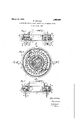
Fig. 1 is a sectional elevation on line '11 r 2 is a plan view on .line'22 of Fig. 1,
-3 is.a section on line of Fi .2. The cylindrical stud 2 mounted on t emachine frame ":11 carries the feeding, disk 3 which has feed teeth 4 in its outer rim and is intermittentlyrrotated for the lengthof the diameter of a ring by means of a ratchet pawl. The feeding disk 3 has an annular groove in which a body 6 is located which has radially directed apertures 7 displaced with regard to one another and designed to 12 designed to receive the ring elements 13 and 14 which are not rotatable and have curvedguides,concentric the'one to the other, said iring, elements '13, 14 serving to guide the ring holders or hooks 8 which haveeach a nose 115 so that they are adjusted into the correct 1 position with regard to the ringformrng tools 16 and 17 when the feeding disk -Sis rotating, inorder to effect the mutual releasing of the rows of meshes.
Two similar opposite working points are auranged the operation being as follows:
. The tube of wire mesh hanging at the one working point at the tools 16 has been gripped by the hooks "of the inner row of rung holders at the rings recently formed, these hooks being in the raised position (Fig. 1),.- The hooks of the corresponding outer; row are at this momentin the lowest posit on so, that rings which are newly ormed and inserted through the rings 19 suspended on the inner row of books encircle the hooks of the outer row. When the feeding disk 3 is further rotated 90 these hooks are controlled the one after the other when 'movmg ifro'm positionl into the position I I (Fig.2) by the curved pieces 13, 14 In such .a manner that at first the hooks of the inner row of books at the left side of F 'ifg. 1 are oscillated in outward direction a'n'dlet drop the meshes of the last row of rings 19 whereupon. the recently "formed rings 18 arecaught on the ends of the hooks belonging to the outer row (Fig. 3 left side) -W11en the rotation ofdisk '3 in the direction of the arrow (Fig.2) of 90 continues (position the holders of. the several rows adopt the position shown at the right side of Fig. 11, those holders which belong :to the inner irow o'fhooks adopt the lowest position and those belonging to the outer row adopting the highest position. In this position of the machine new rings are inserted by the ring forming tools 17 said rings encircling the ring holding hooks of the inner row. After afurther rotation of disk 3 from position III to position IV the ring holders adopt the position shown in Fig. 3 right side, those of the outer row releasing the rings of the last but one row and those of the inner row having gripped the rings which have been last formed.
At a further quarter rotation of disk 3 the ring holders adopt again the position shown in Fig. 1 left side.
The control of the ring holders is effected m that the noses 15 of the ring-holders 8 cooperate with suitable apertures and curved elements of the annular bodies 13 and 1&. When the holders of the inner row oscillate back into their initial position they are lowered by an incline 22 of the annular element 18 until the projection 11 on the holders 8 rest on the feeding disk 3 (Fig. 1 left side). The holders of the outer row on which the ring mesh is hanging slide upward on the incline 23 of the annular element 14 in order to feed the chain mail at a convenient height to the ring-forming tools 17 (Fig. 1 right hand). The operations described are then repeated in inverse order.
The holders of the outer row of holders .are oscillated in outward and inward directions-by the curve 24L of the ring element 14 and lowered by the incline 25 whereupon the holders of the inner row of holders ascend along the incline 26 of the ring element 13 and in this position the chain mail is again conducted towards the ring-forming tools 16.
In this manner the mutual changing of the rows of rings takes place outside the range and independently of the ring forming tools whereby a rapid and secure working of the machine, easy to supervise, is ensured.
I claim 1. In a machine for manufacturing chain mail in tubular shape with opposite working points in which the finished chain mail is alternately held suspended by two groups of opposite ring holders displaced the one with regard to the other, in combination with the inner row of ring holders and with the outer row of ring holders, a fixed axle, a feeding disk rotatably mounted on said fixedaxle and having slots in which said holders are os illatably mounted, means for rotating said disk step by step the distance of one diameter of a ring, a collar on said fixed axle, stationary ring elements fixed on said collar above said feeding disk, cam-like thickenings on said ring elements at points displaced 90 with regard to the points of working, said ring elements acting upon said ring holders in such a manner that when said ring holders are passing through the points of working they are guided by the normal surface of said ring elements so that the mutual position of said ring holders remains the same, the cam-shaped thickenings of said ring elements acting upon said ring holders at points spaced 90 from said working points to make said ring holders carry out the movement required for the chang- 'ing of the row of rings.
2. In a machine for manufacturing chain mail in tubular shape with opposite working points in which the finished chain mail is alternately held suspended by two groups of opposite ring holders displaced the one with regard to the other, in combination with the inner row of ring holders and with the outer row of ring holders, a fixed axle, a feeding disk rotatably mounted on said fixed axle and having slots in which said holders are oscillatably mounted, means for rotating said disk step by step the distance of one diameter of a ring, a collar on said fixed axle, stationary ring elementsfixed on said collar above said feeding disk, cam-like thickenings on said ring elements at points displaced 90 with regard to the points of working, said ring elements acting upon said ring holders in such a manner that when said ring holders are passing through the points of working they areguided by the normal surface of said ring elements so that the camshaped thickenings of said ring elements act upon said ring holders at points spaced 90 from said working points to make said ring holders carry out the movement required for the changing of the row of rings, and a projection at the middle of the outer surface of each ring holder designed to rest upon said feeding disk when said ring holders are in the lowest position, and a nose at the upper end of the same surface of each ring holder which nose cooperates with said camshaped thickenings of said stationary ring elements. i
In testimony whereof I at'fix my signature.
ROBERT EINSELE.
Applications Claiming Priority (1)
| Application Number | Priority Date | Filing Date | Title |
|---|---|---|---|
| DE1663448X | 1922-07-24 |
Publications (1)
| Publication Number | Publication Date |
|---|---|
| US1663448A true US1663448A (en) | 1928-03-20 |
Family
ID=7738634
Family Applications (1)
| Application Number | Title | Priority Date | Filing Date |
|---|---|---|---|
| US5587A Expired - Lifetime US1663448A (en) | 1922-07-24 | 1925-01-29 | Machine for manufacturing chain mail in tubular shape |
Country Status (1)
| Country | Link |
|---|---|
| US (1) | US1663448A (en) |
Cited By (1)
| Publication number | Priority date | Publication date | Assignee | Title |
|---|---|---|---|---|
| US20150367457A1 (en) * | 2010-10-19 | 2015-12-24 | Massachusetts Institute Of Technology | Methods for Digital Composites |
-
1925
- 1925-01-29 US US5587A patent/US1663448A/en not_active Expired - Lifetime
Cited By (1)
| Publication number | Priority date | Publication date | Assignee | Title |
|---|---|---|---|---|
| US20150367457A1 (en) * | 2010-10-19 | 2015-12-24 | Massachusetts Institute Of Technology | Methods for Digital Composites |
Similar Documents
| Publication | Publication Date | Title |
|---|---|---|
| US1663448A (en) | Machine for manufacturing chain mail in tubular shape | |
| US1791378A (en) | Method and machine for mounting coiled filaments | |
| US1666951A (en) | Mesh machine | |
| US2016870A (en) | Knitting machine | |
| US1906741A (en) | Machine for making garment hangers | |
| US1838739A (en) | Machine for knitting pile fabrics | |
| US2009379A (en) | Knitting machine | |
| US1623197A (en) | Process and apparatus for making cups | |
| US2507530A (en) | Fashioned fabric, hosiery, and method of production | |
| US2189276A (en) | Method and apparatus for producing striped knitted fabric | |
| US2185106A (en) | Method of manufacturing grid electrodes | |
| US1417257A (en) | Iaiw ctktv | |
| US2337028A (en) | Cigar machine moistening mechanism | |
| US1397288A (en) | Suspension-sleeve for mesh-machines | |
| US1465446A (en) | Automatic gem-setting machine | |
| US1783337A (en) | Attachment for welding machines | |
| US1496559A (en) | Machine for finishing springs | |
| US2685785A (en) | Machine for the manufacture of knitted fabrics having plain and back stitches | |
| US2247957A (en) | Machine and method for forming bristles | |
| US1897411A (en) | Spring | |
| US1888803A (en) | Forming machine | |
| SU138211A1 (en) | Apparatus for making wire zigzag springs, for example, for a chair | |
| SU869610A1 (en) | Device for indexing planting material to planting apparatus | |
| US615035A (en) | Device for forming breguet coils | |
| JPS58501358A (en) | Device for axially pleating synthetic cylindrical material, especially artificial intestine for sausage production |