US1663447A - Device for lapping in valves - Google Patents
Device for lapping in valves Download PDFInfo
- Publication number
- US1663447A US1663447A US703089A US70308924A US1663447A US 1663447 A US1663447 A US 1663447A US 703089 A US703089 A US 703089A US 70308924 A US70308924 A US 70308924A US 1663447 A US1663447 A US 1663447A
- Authority
- US
- United States
- Prior art keywords
- valve
- axis
- actuating device
- engage
- connecting member
- Prior art date
- Legal status (The legal status is an assumption and is not a legal conclusion. Google has not performed a legal analysis and makes no representation as to the accuracy of the status listed.)
- Expired - Lifetime
Links
- 238000010276 construction Methods 0.000 description 3
- 238000010586 diagram Methods 0.000 description 2
- 239000002184 metal Substances 0.000 description 2
- 241000239290 Araneae Species 0.000 description 1
- 208000035480 Ring chromosome 8 syndrome Diseases 0.000 description 1
- 230000005540 biological transmission Effects 0.000 description 1
- 239000000428 dust Substances 0.000 description 1
- 238000004519 manufacturing process Methods 0.000 description 1
- 230000004048 modification Effects 0.000 description 1
- 238000012986 modification Methods 0.000 description 1
Images

Classifications
-
- B—PERFORMING OPERATIONS; TRANSPORTING
- B24—GRINDING; POLISHING
- B24B—MACHINES, DEVICES, OR PROCESSES FOR GRINDING OR POLISHING; DRESSING OR CONDITIONING OF ABRADING SURFACES; FEEDING OF GRINDING, POLISHING, OR LAPPING AGENTS
- B24B15/00—Machines or devices designed for grinding seat surfaces; Accessories therefor
- B24B15/08—Machines or devices designed for grinding seat surfaces; Accessories therefor for grinding co-operating seat surfaces by moving one over the other
Definitions
- nrcmvinvnn or DAYTON, onro, ASSIGNOR TO THE NATIONAL nnconnme PUMP COMPANY, OF DAYTON, OHIO, A CORPORATION OF OHIO.
- This invention relatesto a device for lappin in'valves. has been customary to rotate the valve in a fixed plane thereby dressing or lapping in only that portion of the surfaceof the valve which engages the valve seat when the valve isin a single predetermined position.
- valves are provided with contact surfaces which are curved to conform substantially to the contour of a portion ofa sphere, so as to fully engage the valve seat when the valve is tilted, and when such a valve is lapped in as above described the spherical surface is deformed, because a portion only thereof will engage the seat during the lapping in operation.
- One object of the present invention is to provide a device of this kind which will operate to quickly and accurately fit the valve to the valve seat.
- a further object of the invention is to i provide such a device which will lap in the entire contact surface of a spherical valve and maintain the same in true spherical form, thus insuring the proper seating of the valve when tilted.
- a further object ofthe invention is to provide such a device which will be simple in its construction, easy to operate and inexpensive to manufacture.
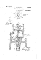
- Fig. 1 is a side elevation of a lapping in deviceand its operating mechanism, embodying my invention
- Fig. 2 is a vertical ectional view taken centrally of the lapping in device and partly broken away
- Fig. 3 is a plan view of the eccentric gearing
- Fig. 4 is a diagram of the path of movement of the valve tilting member
- the particular valve structure here shown comprises a housingQ having its lower portion provided with external screw threads 3 and its upper end provided with internal screw threads 4: whereby it may be connected with the other elements of the pump mechanism.
- This housing also has an inwardly extending annular flange 5 the upper corner of which constitutes the valve seat on which the valve member is seated, this corner being-,- if desired, slightly beveled, as shown at) 6, to increase the area of contact.
- the lower iportion of the housing is provided above the threaded portion thereof with an outwardly extending flange 7 hen a valve of this character is to be lapped in and the valve seat is to be used as the annular friction element the valve housing 2 is mounted on the supporting structure 1 with the valve in position therein.
- the supporting structure 1 of the present device is provided at its upper end with an annular member or ring 8 which will receive the lower threaded portion 3 of the housing and engage the flange 7 so as to support the housing thereon. I have not found it necessary to provide any means for securing the housing in position on the ring8 but obviously this could be done if desirable.
- the ring 8 should be separate from the body portion of the supporting structure 1, of which it forms a part, and, ashere shown, it issecured'to the upper edge of that structure by means of suitable fastening devices, such If desired, the valve seat two. points on the periphery thereof will be substantially equal to the diameter of the valve seat. Consequently the contact surface of the valve will properly engage the valve seat when the valve is seated thereon regardless of whether the body of the valve is in a plane parallel with the plane-of the valve seat.
- the valve also has a stem 12 which extends through the valve seat and projects some distance below the same.
- the Y valve is rotated about an axis extending lengthwise of the housing 2 and during this rotation'is moved about a transverse axis to tilt the valve member and thus cause all portions o f its contact surface tobe brought into contact with'the valve seat during the lappingiin operation.
- the transverse axis about which the valve is tilted is preferably substantially coincident with the axis about which the spherical contactsurface of the valve is described, thus maintaining the valve at-allxtiines in proper relation to its seat.
- any suitable means may be provided for r0- tatingythe valve with itscontact surface in engagement with the annular friction ele- 111(3I1h,'01 valve seat, and I prefer to provide a rotatable actuating device which is arranged above the valve seat for rotation about'an axis extending lengthwise ofthe housing'and, as here shown, this actuating device is in the form of a spindle 13.
- a connecting member 1% which, in the present construction, is in the form of a spider having three arms 15, the lower ends of which are seated in recesses formed in the upper surface of the valve.
- the upper end of.the-connecting member is pivotally connected with the rotatable actuating device and held against rotation relatively thereto.
- the connection between the actuating device and the connection member is a universal one so that the axis about which the connecting member moves may intersect the axis of the actuating device in any direction.
- the upper end of the connecting member is provided with a spherical'head 17 which is seated in a socket 18 carried by the lower end of the spindle 13.
- This spherical head is provided with pins 19 which extend into slots 20 formed in walls of the socket, thereby holding the spindle and the connecting member against relative rotation...
- the means for tilting the valve during the rotation thereof may take various forms but this mechanism should be of such a character that the valve will be rocked about the axis of the connecting member more or less frequent-y during its rotation.
- This tilting or rocking movement of the valve not only brings all arts oft-he contact .surfa cc of the valve into engagement with the valve seat butit CILlSQSt'lllS surface to engagethe valve seatwith .a wiping action which expedites the dressingor-lapping in ofthe parts.
- Thenicans :for so tilting :the valve preferably comprises an actuating member which is movabletransversely to the axis of rotation ofthe valve andzhas movementtoward and from said axis in difi'erentzpaths.
- the present construction I have provided the main supporting structure 1, in the lower portion thereof, with a vertical bearing 21 in which is journaleda shaft 22 the upper end ofwhich'has formed therein a vertical bearing 23 arranged eccentrically to the axis of the shaft 22.
- Journaled in the bearing 23 is a stud 24 having secured to its upper end, and preferably formed integral therewith, a pinion which rests on the upper end of 1e shaft 22 and is rotatable relativelythereto.
- This pinion is arranged within and meshes with an internal gearor annular rack of adi'ameter some-what greater-than the diametcrof the pinion.
- This internal vgear is s pported by an annularboss;27extending upwardly aboutthe upper end of the shaft 22 and is held against relative rotation to that boss. Consequently-ms the pinion rotates about the-axis of the shaft22it will travel about'the internal gear and will be rotated thereby.
- an actuating member here shown as a pin 28 seated in the pinion 25 and extending above the same.
- the upperwendof this pin is so connected withthe stem 12 of the valve as to cause the-lowerendofthe valve stem to move there-with;
- the upper end of the stem has a spherical head 29 arranged within a socket 30 in the lower end of the valve stem.
- a protecting cover may be provided toiprevent the entrance-of'metal dust or other foreign matter into the gearingand bearings of the tilting mechanism. As hcre shown, this cover is in the form of a-plate 31resting upon theupper end ofthc boss 27 Land having a depending flange 32.
- the path of movement of this actuating de vice is along a series of transverse lines which intersect one another and this path extends toward and ,fromthe axis of rotation of the valve in various directions.
- the path defined by the actuating device in one complete rotation of the shaft 22 will be ape proximately that shown in the diagram of i and, as will be noted, comprises a series of loops extending radially from the axis of rotation of the valve. It will be understood, of course, that thispathmay take various forms.
- the driving mechanism for the lapping in device may take any suitable form but, in the present instance, I have associated this device with a driving mechanism similar to a drill press.
- the supporting structure 1 is mounted on a base 33 from which a standard 34 extends upwardly, this standard having its upper end turned at an angle thereto and provided with a vertical bearing 35 in which the'spindle 13 is journaled.
- a driving shaft 36 is journaled in the lower portion of the standard 234i and extends into thesupporting structure 1 where it is connected by means of beveled gearing 37 with the shaft 22.
- the outer end of the shaft 36 is provided with a driving pulley 38 and with a' series of stepped transmission pulleys 39, any one of which may be connected by means of a belt 40 with a pulley 42 on the upper endof the spindle 13.
- the ratio of the driving connection between the spindle and the shaft 22' is preferably such that the spindle will rotate at a considerably greater speed than'the,
- an element having an annular part to engage the surface of a valve, meansfor rotating said valve in contact with said part, and a device having movement transverse to the axis of rotation of said valve and adapted to be operatively connected with said valve independently of said actuating device.
- an element having an annular part to engage the surface of a valve, means for rotating said valve in contact with said part. and a device having movement in a plurality of different directions transverse to the axis invention
- an element having an annular part to engage the surface of a valve, means for rotating said valve in contact with said part, and a device having movement in paths which form a plurality of loops extending in dilferent directions from the axis of rotation of said valve, said device being adapted for operative connection with said valve.
- an element having an annular part to engage the surface of a valve and through which the stem of said valve extends, a rotatable actuating device, a connecting member interposed between said valve and said ac tuating device and pivotally connected with said actuating device, a device rotatable about an axis substantially parallel with the axis of said actuating device .and having a part arranged eccentrically thereof and adapted to be connected with the stem of said valve.
- an element having an annular part to engage the surface of said valve, a rotatable actuating device, a connecting member interposed between said actuating device and said valve and pivotally connected with said actuating device, a shaftrotatable about an axis substantially parallel with the axis of said actuating device, and a part eccentrically connected with said shaft and adapted to be connected with said valve to move the same about the axis of said connectingmemher.
- an element having an annular part to engage the surface of a valve, a rotatable actuating device, a connectingmemberinterposed between said actuating device and said valve and pivotally connected with said actuating device, a shaft rotatable about an axis substantially parallel with the axis of said actuating device, a part eccentrically connected with said shaft and rotatablerelartively thereto, and a second parteccentrically mounted on the first mentioned part to engage the surfacecof a valve, a rotatable actuating device, a connecting member interposed between said actuating device and said valve and pivotally connected with said actuating device, a shaft rotatable about an axis substantially parallel with the axis of said actuating device, a pinionrotatably mounted on said shaft eccentrically to the axis thereof, an annular rack surrounding said pinion and meshing therewith, and-a part mounted on said pinion eccentrically to the axis thereof for connecting the same with said valve
- an element having an annular part to engage the surface of a valve and through which the stem of said valve extends, a rotatable actuating device, a connecting member interposed between said valve and said actuating device, and pivotally con-c nected with said actuatin device, a shaft rotatable about an axis substantially par allel with the axis of said actuating device, a pinion carried by said shaft for rotation about an axis parallel with'but out of line with said axis, an annular rack surrounding said pinion and meshing therewith, and a partmounted on said pinion outof "line with the axisthereof and adapted to engage the stem of said valve.
- a structure having means to support a housing having a valve chamber and a valve seat within said chamber, an actuating device to rotate a valve on said seat, and means carried by said structure on that side of said valve opposite said actuating device for tilting the valve while it is being rotated.
- a structure having means to support a housing having a valve chamber and a valve seat within said chamber, a spindle rotatable about an axis extending lengthwise ofsaid housing-, a member for connecting said spindle with a valve on said valve seat, said .member having universal pivotal connection with said spindle, a device movablein, a;path transverse to the axisof said spindle for moving said valve about the axisof said connecting member.
- a structure having means to support a housing having a valve chamber and a valveseat within said chamber, an actuating device mounted for rotation about an axis extending lengthwise of said housing, a member to connect said actuating device with said valve, said member being pivotally connected with said actuating device, a shaft rotatable about an axis substantially parallel to theaxis of said actuating device, and a part eccentrically connected with said shaft adapted to impart'movement to said valve about the axis of said connecting member;
- a structure having means to support a housing having a valve chamber and a valve seat within said chamber, anactuating device mounted for rotation about an axis extending lengthwise of said housing, a member to connect said actuating device with said valve, said member being pivotally connected with said actuating device, a-shaft mounted for rotation about an axis substantially parallel with the axis of said actuating device, a pinion rotatably mounted on an axis extending parallel tobut offset from the axis of said shaft, a fixed annular rack with which said pinion meshes, and a part carried by said pinion and arranged eccentrically to the axis thereof for imparting movement to said valve about the axis of-said connecting member.
- a stationary element having an annular part to engage the surface of a valve, and separately operated devices each having means for connectingit with said valve, for rotating said valve in contact with said part and for tilting saidvalve with relation to said part during the rotation of said valve.
- a stationary element having, an an nular part to engage the surface of a valve, and devices having means for, separately connecting the same with said valve for rotating said valve in contact with said part about alongitudinal axis and for simultaneously about said transverse axis of said connecting member While it is being rotated'by said actuating device.
- a stationary element having an annular part to engage the surface of a valve, a rotatable actuating device spaced from said part, a connecting member having universal connection With said actuating device and engaging said valve to rotate the same,
- a stationary element having an annular part to engage the surface of a valve
- a spindle rotatable about an axis extending through said annular part and having a socket, a connecting member having a head seated in said socket and held against rotation relatively thereto, the other end of said connecting member engaging said valve to impart rotation thereto, and driven means directly actuating said valve for tilting said valve and said connecting member with relation to said spindle.
- a stationary element having an annular part to engage the surface of a valve, an actuating device rotatable about an axis extending through said annular part, a connecting member pivotally secured to said actuating device for movement about a transverse axis and having a plurality of arms to engage recesses in said valve, and means independent of said connecting member to directly engage said valve and positively move said valve about said transverse axis of said connecting ,member.
- a structure having stationary means to support a housing having a valve chamher and a valve seat Within said chamber, an actuating device to rotate a valve on said seat, and driven means separate from said actuating device and acting directly on said valve for tilting said valve while it is being rotated.
Landscapes
- Engineering & Computer Science (AREA)
- Mechanical Engineering (AREA)
- Mechanically-Actuated Valves (AREA)
Description
' March 20, 1928. v 1,663,447
. E. E. EICKMEYER DEVICE FOR LAPPING IN VALVES 1 Filed March 31, 1924 2 Sheets-Sheet 1 E Ti 9-1- ATTORNEY March 20, 1928.
1,663,447 E. EICKMEYER DEVICE FOR LAPPING IN VALVES Filed March 31. 1924 2 Sheets-Sheet 2 v I I2 31 28 Z5 2 1 1 I r M EARL JEWJFQR I ATTORNEY Patented Mar. 20, 1928.
. pairs!) STATES EARL E.
PATENT OFFICE.
nrcmvinvnn, or DAYTON, onro, ASSIGNOR TO THE NATIONAL nnconnme PUMP COMPANY, OF DAYTON, OHIO, A CORPORATION OF OHIO.
DEVICE FOR LAPPING IN- VALVES.
Application filed March 31, 1924. :Serial No. 703,089.
This invention relatesto a device for lappin in'valves. has been customary to rotate the valve in a fixed plane thereby dressing or lapping in only that portion of the surfaceof the valve which engages the valve seat when the valve isin a single predetermined position.
the valve is tilted slightly on its seat the contact is imperfect and the valve will leak. Some valves are provided with contact surfaces which are curved to conform substantially to the contour of a portion ofa sphere, so as to fully engage the valve seat when the valve is tilted, and when such a valve is lapped in as above described the spherical surface is deformed, because a portion only thereof will engage the seat during the lapping in operation. I
One object of the present inventionis to provide a device of this kind which will operate to quickly and accurately fit the valve to the valve seat.
A further object of the invention is to i provide such a device which will lap in the entire contact surface of a spherical valve and maintain the same in true spherical form, thus insuring the proper seating of the valve when tilted.
A further object ofthe invention is to provide such a device which will be simple in its construction, easy to operate and inexpensive to manufacture.
Other objects of the invention will appear as the mechanism is described in detail.
In the accompanying drawings Fig. 1 is a side elevation of a lapping in deviceand its operating mechanism, embodying my invention; Fig. 2 is a vertical ectional view taken centrally of the lapping in device and partly broken away; Fig. 3 is a plan view of the eccentric gearing; and Fig. 4 is a diagram of the path of movement of the valve tilting member;
In these drawings I have illustrated one embodiment: of my invention and have shown the same as designed primarily for lapping in the foot valve of a gasoline pump but it will be understoodthat the mechanism may take various forms and'that the device may be used in connection .with valves of various kinds without departing from the spirit of the invention.
In that form here shown the device'comprises a supporting structure or main frame In devices of this kind it 1 having means for supporting thereon an element having an annular part to engage the contact surface of the valve. This annular element corresponds exactly to the valve seat so that when the valve has been finished or lapped in it will fit perfectly on the valve seat. itself is utilized as this annular friction or rubbing element so thatthe lapping in operation will fit the valve perfectly to the seat with whichit is to cooperate when in use. It is not necessary to the operation of the device that the valveseat should be used as the friction member and it will be obvious that a separate friction member may be substituted for the valve housing should this be desirable for any reason, as for example, when it is preferable that the friction member should be formed of metal different from the valve. The particular valve structure here shown comprises a housingQ having its lower portion provided with external screw threads 3 and its upper end provided with internal screw threads 4: whereby it may be connected with the other elements of the pump mechanism. This housing also has an inwardly extending annular flange 5 the upper corner of which constitutes the valve seat on which the valve member is seated, this corner being-,- if desired, slightly beveled, as shown at) 6, to increase the area of contact.
The lower iportion of the housing is provided above the threaded portion thereof with an outwardly extending flange 7 hen a valve of this character is to be lapped in and the valve seat is to be used as the annular friction element the valve housing 2 is mounted on the supporting structure 1 with the valve in position therein. In order to properly support the valve housing the supporting structure 1 of the present device is provided at its upper end with an annular member or ring 8 which will receive the lower threaded portion 3 of the housing and engage the flange 7 so as to support the housing thereon. I have not found it necessary to provide any means for securing the housing in position on the ring8 but obviously this could be done if desirable. I prefer that the ring 8 should be separate from the body portion of the supporting structure 1, of which it forms a part, and, ashere shown, it issecured'to the upper edge of that structure by means of suitable fastening devices, such If desired, the valve seat two. points on the periphery thereof will be substantially equal to the diameter of the valve seat. Consequently the contact surface of the valve will properly engage the valve seat when the valve is seated thereon regardless of whether the body of the valve is in a plane parallel with the plane-of the valve seat. The valve also has a stem 12 which extends through the valve seat and projects some distance below the same.
'When the valve structure as a whole has been mounted on the lappingin device the Y valve is rotated about an axis extending lengthwise of the housing 2 and during this rotation'is moved about a transverse axis to tilt the valve member and thus cause all portions o f its contact surface tobe brought into contact with'the valve seat during the lappingiin operation. The transverse axis about which the valve is tilted is preferably substantially coincident with the axis about which the spherical contactsurface of the valve is described, thus maintaining the valve at-allxtiines in proper relation to its seat.
Any suitable means may be provided for r0- tatingythe valve with itscontact surface in engagement with the annular friction ele- 111(3I1h,'01 valve seat, and I prefer to provide a rotatable actuating device which is arranged above the valve seat for rotation about'an axis extending lengthwise ofthe housing'and, as here shown, this actuating device is in the form of a spindle 13. Interposed between the actuating device and the valve is a connecting member 1% which, in the present construction, is in the form of a spider having three arms 15, the lower ends of which are seated in recesses formed in the upper surface of the valve. The upper end of.the-connecting member is pivotally connected with the rotatable actuating device and held against rotation relatively thereto. Preferably the connection between the actuating device and the connection member is a universal one so that the axis about which the connecting member moves may intersect the axis of the actuating device in any direction. As here shown, the upper end of the connecting member is provided with a spherical'head 17 which is seated in a socket 18 carried by the lower end of the spindle 13. This spherical head is provided with pins 19 which extend into slots 20 formed in walls of the socket, thereby holding the spindle and the connecting member against relative rotation...
The means for tilting the valve during the rotation thereof may take various forms but this mechanism should be of such a character that the valve will be rocked about the axis of the connecting member more or less frequent-y during its rotation. This tilting or rocking movement of the valve not only brings all arts oft-he contact .surfa cc of the valve into engagement with the valve seat butit CILlSQSt'lllS surface to engagethe valve seatwith .a wiping action which expedites the dressingor-lapping in ofthe parts. Thenicans :for so tilting :the valve preferably comprises an actuating member which is movabletransversely to the axis of rotation ofthe valve andzhas movementtoward and from said axis in difi'erentzpaths. In;-the present construction I have provided the main supporting structure 1, in the lower portion thereof, with a vertical bearing 21 in which is journaleda shaft 22 the upper end ofwhich'has formed therein a vertical bearing 23 arranged eccentrically to the axis of the shaft 22. Journaled in the bearing 23 is a stud 24 having secured to its upper end, and preferably formed integral therewith, a pinion which rests on the upper end of 1e shaft 22 and is rotatable relativelythereto. This pinion is arranged within and meshes with an internal gearor annular rack of adi'ameter some-what greater-than the diametcrof the pinion. This internal vgear is s pported by an annularboss;27extending upwardly aboutthe upper end of the shaft 22 and is held against relative rotation to that boss. Consequently-ms the pinion rotates about the-axis of the shaft22it will travel about'the internal gear and will be rotated thereby. Mounted on the pinion and arranged eccentrically of the axisthereof. is an actuating member, here shown as a pin 28 seated in the pinion 25 and extending above the same. The upperwendof this pin is so connected withthe stem 12 of the valve as to cause the-lowerendofthe valve stem to move there-with; In the present instance, the upper end of the stem has a spherical head 29 arranged within a socket 30 in the lower end of the valve stem. If desired, a protecting cover may be provided toiprevent the entrance-of'metal dust or other foreign matter into the gearingand bearings of the tilting mechanism. As hcre shown, this cover is in the form of a-plate 31resting upon theupper end ofthc boss 27 Land having a depending flange 32. The pin-28-extends through this cover and'thus serves to connectthe same with the pinion so that it will move therewith, the diameter'of the cover being sufficient to permit'of this movement withrelation to the:boss. .It will be apparent that the double eccentric movement thus imparted to the actuating member 28 will carry the lower end of the valve stem transversely to the axis of rotation of the valve and will cause the valve to be tilted first in one direction and then in another.
The path of movement of this actuating de vice is along a series of transverse lines which intersect one another and this path extends toward and ,fromthe axis of rotation of the valve in various directions. The path defined by the actuating device in one complete rotation of the shaft 22 will be ape proximately that shown in the diagram of i and, as will be noted, comprises a series of loops extending radially from the axis of rotation of the valve. It will be understood, of course, that thispathmay take various forms.
The driving mechanism for the lapping in device may take any suitable form but, in the present instance, I have associated this device with a driving mechanism similar to a drill press. The supporting structure 1 is mounted on a base 33 from which a standard 34 extends upwardly, this standard having its upper end turned at an angle thereto and provided with a vertical bearing 35 in which the'spindle 13 is journaled. A driving shaft 36 is journaled in the lower portion of the standard 234i and extends into thesupporting structure 1 where it is connected by means of beveled gearing 37 with the shaft 22. The
outer end of the shaft 36 is provided with a driving pulley 38 and with a' series of stepped transmission pulleys 39, any one of which may be connected by means of a belt 40 with a pulley 42 on the upper endof the spindle 13. The ratio of the driving connection between the spindle and the shaft 22' is preferably such that the spindle will rotate at a considerably greater speed than'the,
While I have shown and described one embodiment of my invention I wish it to be understood that I do not desire to be limited to the details thereof as various modifications may appear to a person skilled, in the art.
Having now fully described my what I claim as new and desire Letters Patent, is:
1. In a mechanism of the character described, an element having an annular part to engage the surface of a valve, meansfor rotating said valve in contact with said part, and a device having movement transverse to the axis of rotation of said valve and adapted to be operatively connected with said valve independently of said actuating device.
2. In a mechanism of the character described, an element having an annular part to engage the surface of a valve, means for rotating said valve in contact with said part. and a device having movement in a plurality of different directions transverse to the axis invention,
to secure by rotating said valve in'contact with said part,
and a device having movement in intersecting paths transverse to the axis of rotation of said valve, and adapted to be operatively connected with said valve.
4:. In a mechanism of the character described, an element having an annular part to engage the surface of a valve, means for rotating said valve in contact with said part, and a device having movement in paths which form a plurality of loops extending in dilferent directions from the axis of rotation of said valve, said device being adapted for operative connection with said valve.
5. In a device. of the charac-terdescribed,
an element having an annular part to engage which the stem of said valve extends, a rotatable actuating device, a connecting member interposed between said valve and said actuating device and pivotally connected with said actuating device, and a device movable transversely to the axis of said actuating device and adapted to engage the stem'of said valve to move the latter about the axis of said connecting member.
- 7. In a mechanism of the character described, an element having an annular part to engage the surface of a valve and through which the stem of said valve extends, a rotatable actuating device, a connecting member interposed between said valve and said ac tuating device and pivotally connected with said actuating device, a device rotatable about an axis substantially parallel with the axis of said actuating device .and having a part arranged eccentrically thereof and adapted to be connected with the stem of said valve.
8. In a mechanism of the character de scribed, an element having an annular part to engage the surface of said valve, a rotatable actuating device, a connecting member interposed between said actuating device and said valve and pivotally connected with said actuating device, a shaftrotatable about an axis substantially parallel with the axis of said actuating device, and a part eccentrically connected with said shaft and adapted to be connected with said valve to move the same about the axis of said connectingmemher. 7 i
9. In a mechanism of the character described, an element having an annular part to engage the surface of a valve, a rotatable actuating device, a connectingmemberinterposed between said actuating device and said valve and pivotally connected with said actuating device, a shaft rotatable about an axis substantially parallel with the axis of said actuating device, a part eccentrically connected with said shaft and rotatablerelartively thereto, and a second parteccentrically mounted on the first mentioned part to engage the surfacecof a valve, a rotatable actuating device, a connecting member interposed between said actuating device and said valve and pivotally connected with said actuating device, a shaft rotatable about an axis substantially parallel with the axis of said actuating device, a pinionrotatably mounted on said shaft eccentrically to the axis thereof, an annular rack surrounding said pinion and meshing therewith, and-a part mounted on said pinion eccentrically to the axis thereof for connecting the same with said valve.
11. In a mechanism of the character described, an element having an annular part to engage the surface of a valve and through which the stem of said valve extends, a rotatable actuating device, a connecting member interposed between said valve and said actuating device, and pivotally con-c nected with said actuatin device, a shaft rotatable about an axis substantially par allel with the axis of said actuating device, a pinion carried by said shaft for rotation about an axis parallel with'but out of line with said axis, an annular rack surrounding said pinion and meshing therewith, and a partmounted on said pinion outof "line with the axisthereof and adapted to engage the stem of said valve.
12. In a mechanism of the character described, a structure having means to support a housing having a valve chamber and a valve seat within said chamber, an actuating device to rotate a valve on said seat, and means carried by said structure on that side of said valve opposite said actuating device for tilting the valve while it is being rotated. i 13. In a mechanism of the character described, a structure having means to support a housing having a valve chamber and a valve seat within said chamber, a spindle rotatable about an axis extending lengthwise ofsaid housing-,a member for connecting said spindle with a valve on said valve seat, said .member having universal pivotal connection with said spindle, a device movablein, a;path transverse to the axisof said spindle for moving said valve about the axisof said connecting member.
let. In a mechanism of the character described,-a structure having means to support a housing having a valve chamber and a valveseat within said chamber, an actuating device mounted for rotation about an axis extending lengthwise of said housing, a member to connect said actuating device with said valve, said member being pivotally connected with said actuating device, a shaft rotatable about an axis substantially parallel to theaxis of said actuating device, and a part eccentrically connected with said shaft adapted to impart'movement to said valve about the axis of said connecting member;
15. In a mechanism ofthe character described, a structurehaving means to support a housing having a valve chamber and a valve seat within said chamber, anactuating device mounted for rotation about an axis extending lengthwise of said housing, a member to connect said actuating device with said valve, said member being pivotally connected with said actuating device, a-shaft mounted for rotation about an axis substantially parallel with the axis of said actuating device, a pinion rotatably mounted on an axis extending parallel tobut offset from the axis of said shaft, a fixed annular rack with which said pinion meshes, and a part carried by said pinion and arranged eccentrically to the axis thereof for imparting movement to said valve about the axis of-said connecting member.
16. In a mechanism of thecharacter described, a stationary element having an annular part to engage the surface of a valve, and separately operated devices each having means for connectingit with said valve, for rotating said valve in contact with said part and for tilting saidvalve with relation to said part during the rotation of said valve.
17. In a mechanism of the character described, a stationary element having, an an nular part to engage the surface of a valve, and devices having means for, separately connecting the same with said valve for rotating said valve in contact with said part about alongitudinal axis and for simultaneously about said transverse axis of said connecting member While it is being rotated'by said actuating device.
20. In a mechanism of the character described, a stationary element having an annular part to engage the surface of a valve, a rotatable actuating device spaced from said part, a connecting member having universal connection With said actuating device and engaging said valve to rotate the same,
and driven means directly actuating said valve independently of said connecting mem her for tilting said valve with relation to said part of said element.
21. In a mechanism of the character described, a stationary element having an annular part to engage the surface of a valve,
a spindle rotatable about an axis extending through said annular part and having a socket, a connecting member having a head seated in said socket and held against rotation relatively thereto, the other end of said connecting member engaging said valve to impart rotation thereto, and driven means directly actuating said valve for tilting said valve and said connecting member with relation to said spindle.
22. In a mechanism of the character described, a stationary element having an annular part to engage the surface of a valve, an actuating device rotatable about an axis extending through said annular part, a connecting member pivotally secured to said actuating device for movement about a transverse axis and having a plurality of arms to engage recesses in said valve, and means independent of said connecting member to directly engage said valve and positively move said valve about said transverse axis of said connecting ,member.
23. In a mechanism of the character described, a structure having stationary means to support a housing having a valve chamher and a valve seat Within said chamber, an actuating device to rotate a valve on said seat, and driven means separate from said actuating device and acting directly on said valve for tilting said valve while it is being rotated.
In testimony whereof, I alfix my signature Y hereto.
EARL E. EIOKMEYER.
Priority Applications (1)
| Application Number | Priority Date | Filing Date | Title |
|---|---|---|---|
| US703089A US1663447A (en) | 1924-03-31 | 1924-03-31 | Device for lapping in valves |
Applications Claiming Priority (1)
| Application Number | Priority Date | Filing Date | Title |
|---|---|---|---|
| US703089A US1663447A (en) | 1924-03-31 | 1924-03-31 | Device for lapping in valves |
Publications (1)
| Publication Number | Publication Date |
|---|---|
| US1663447A true US1663447A (en) | 1928-03-20 |
Family
ID=24823959
Family Applications (1)
| Application Number | Title | Priority Date | Filing Date |
|---|---|---|---|
| US703089A Expired - Lifetime US1663447A (en) | 1924-03-31 | 1924-03-31 | Device for lapping in valves |
Country Status (1)
| Country | Link |
|---|---|
| US (1) | US1663447A (en) |
Cited By (1)
| Publication number | Priority date | Publication date | Assignee | Title |
|---|---|---|---|---|
| US2558649A (en) * | 1946-07-05 | 1951-06-26 | Gemeinhardt Walter | Means for shaping the bores of mouthpieces |
-
1924
- 1924-03-31 US US703089A patent/US1663447A/en not_active Expired - Lifetime
Cited By (1)
| Publication number | Priority date | Publication date | Assignee | Title |
|---|---|---|---|---|
| US2558649A (en) * | 1946-07-05 | 1951-06-26 | Gemeinhardt Walter | Means for shaping the bores of mouthpieces |
Similar Documents
| Publication | Publication Date | Title |
|---|---|---|
| KR930006787B1 (en) | Roundness processing device of a slipper surface of a rocker arm | |
| US2493206A (en) | Lens grinding and polishing machine | |
| US1840254A (en) | Polishing apparatus | |
| US1663447A (en) | Device for lapping in valves | |
| US2215288A (en) | Washing machine mechanism | |
| US2082108A (en) | Washing machine | |
| US2649669A (en) | Appliance for lapping flat annular surfaces or disks | |
| US2086942A (en) | Pressure relief valve | |
| US1131611A (en) | Valve-grinding machine. | |
| US1404103A (en) | Valve | |
| US1801847A (en) | Combination hot and cold water faucet | |
| US2817463A (en) | Valve arrangement for the discharge of material from a space below atmospheric pressure and like purposes | |
| US1963884A (en) | Lapping machine | |
| US2233246A (en) | Fluid meter | |
| US1611452A (en) | Lubricating machine | |
| US2365105A (en) | Liquid control valve | |
| US2159620A (en) | Lens grinding and polishing machine | |
| US3071902A (en) | Valve seat refacing apparatus | |
| US2240573A (en) | Valve and stop for wobbler motors | |
| US2338509A (en) | Grinding machine | |
| US2037443A (en) | Dynamic balancing machine | |
| US1494166A (en) | Thrust device | |
| US2435126A (en) | Formation of curved surfaces of prescribed figure by grinding and/or polishing | |
| US415886A (en) | Grinding-machine | |
| US2434463A (en) | Valve seat grinder |