US1663444A - Tinning apparatus - Google Patents
Tinning apparatus Download PDFInfo
- Publication number
- US1663444A US1663444A US756742A US75674224A US1663444A US 1663444 A US1663444 A US 1663444A US 756742 A US756742 A US 756742A US 75674224 A US75674224 A US 75674224A US 1663444 A US1663444 A US 1663444A
- Authority
- US
- United States
- Prior art keywords
- rollers
- tin
- plates
- feed
- compartment
- Prior art date
- Legal status (The legal status is an assumption and is not a legal conclusion. Google has not performed a legal analysis and makes no representation as to the accuracy of the status listed.)
- Expired - Lifetime
Links
- ATJFFYVFTNAWJD-UHFFFAOYSA-N Tin Chemical compound [Sn] ATJFFYVFTNAWJD-UHFFFAOYSA-N 0.000 description 63
- 230000004907 flux Effects 0.000 description 23
- 239000003921 oil Substances 0.000 description 19
- 235000019198 oils Nutrition 0.000 description 19
- 230000007246 mechanism Effects 0.000 description 17
- 239000011248 coating agent Substances 0.000 description 12
- 238000000576 coating method Methods 0.000 description 12
- XEEYBQQBJWHFJM-UHFFFAOYSA-N Iron Chemical compound [Fe] XEEYBQQBJWHFJM-UHFFFAOYSA-N 0.000 description 10
- 239000005028 tinplate Substances 0.000 description 8
- 229910001128 Sn alloy Inorganic materials 0.000 description 6
- 239000000571 coke Substances 0.000 description 6
- NNIPDXPTJYIMKW-UHFFFAOYSA-N iron tin Chemical compound [Fe].[Sn] NNIPDXPTJYIMKW-UHFFFAOYSA-N 0.000 description 6
- 239000013078 crystal Substances 0.000 description 5
- 229910052742 iron Inorganic materials 0.000 description 5
- 238000004519 manufacturing process Methods 0.000 description 5
- CWYNVVGOOAEACU-UHFFFAOYSA-N Fe2+ Chemical compound [Fe+2] CWYNVVGOOAEACU-UHFFFAOYSA-N 0.000 description 3
- 229910045601 alloy Inorganic materials 0.000 description 3
- 239000000956 alloy Substances 0.000 description 3
- 238000010276 construction Methods 0.000 description 3
- 239000002932 luster Substances 0.000 description 3
- 229910000831 Steel Inorganic materials 0.000 description 2
- 238000010438 heat treatment Methods 0.000 description 2
- 230000001788 irregular Effects 0.000 description 2
- 239000010959 steel Substances 0.000 description 2
- PSBDWGZCVUAZQS-UHFFFAOYSA-N (dimethylsulfonio)acetate Chemical compound C[S+](C)CC([O-])=O PSBDWGZCVUAZQS-UHFFFAOYSA-N 0.000 description 1
- 235000019482 Palm oil Nutrition 0.000 description 1
- 241001302210 Sida <water flea> Species 0.000 description 1
- 230000001464 adherent effect Effects 0.000 description 1
- 239000003610 charcoal Substances 0.000 description 1
- 238000009499 grossing Methods 0.000 description 1
- 239000000463 material Substances 0.000 description 1
- 238000002844 melting Methods 0.000 description 1
- 230000008018 melting Effects 0.000 description 1
- 239000002540 palm oil Substances 0.000 description 1
- 238000005192 partition Methods 0.000 description 1
- 230000008439 repair process Effects 0.000 description 1
- 239000000126 substance Substances 0.000 description 1
Images

Classifications
-
- C—CHEMISTRY; METALLURGY
- C23—COATING METALLIC MATERIAL; COATING MATERIAL WITH METALLIC MATERIAL; CHEMICAL SURFACE TREATMENT; DIFFUSION TREATMENT OF METALLIC MATERIAL; COATING BY VACUUM EVAPORATION, BY SPUTTERING, BY ION IMPLANTATION OR BY CHEMICAL VAPOUR DEPOSITION, IN GENERAL; INHIBITING CORROSION OF METALLIC MATERIAL OR INCRUSTATION IN GENERAL
- C23C—COATING METALLIC MATERIAL; COATING MATERIAL WITH METALLIC MATERIAL; SURFACE TREATMENT OF METALLIC MATERIAL BY DIFFUSION INTO THE SURFACE, BY CHEMICAL CONVERSION OR SUBSTITUTION; COATING BY VACUUM EVAPORATION, BY SPUTTERING, BY ION IMPLANTATION OR BY CHEMICAL VAPOUR DEPOSITION, IN GENERAL
- C23C2/00—Hot-dipping or immersion processes for applying the coating material in the molten state without affecting the shape; Apparatus therefor
- C23C2/14—Removing excess of molten coatings; Controlling or regulating the coating thickness
- C23C2/22—Removing excess of molten coatings; Controlling or regulating the coating thickness by rubbing, e.g. using knives, e.g. rubbing solids
-
- C—CHEMISTRY; METALLURGY
- C23—COATING METALLIC MATERIAL; COATING MATERIAL WITH METALLIC MATERIAL; CHEMICAL SURFACE TREATMENT; DIFFUSION TREATMENT OF METALLIC MATERIAL; COATING BY VACUUM EVAPORATION, BY SPUTTERING, BY ION IMPLANTATION OR BY CHEMICAL VAPOUR DEPOSITION, IN GENERAL; INHIBITING CORROSION OF METALLIC MATERIAL OR INCRUSTATION IN GENERAL
- C23C—COATING METALLIC MATERIAL; COATING MATERIAL WITH METALLIC MATERIAL; SURFACE TREATMENT OF METALLIC MATERIAL BY DIFFUSION INTO THE SURFACE, BY CHEMICAL CONVERSION OR SUBSTITUTION; COATING BY VACUUM EVAPORATION, BY SPUTTERING, BY ION IMPLANTATION OR BY CHEMICAL VAPOUR DEPOSITION, IN GENERAL
- C23C2/00—Hot-dipping or immersion processes for applying the coating material in the molten state without affecting the shape; Apparatus therefor
- C23C2/04—Hot-dipping or immersion processes for applying the coating material in the molten state without affecting the shape; Apparatus therefor characterised by the coating material
- C23C2/08—Tin or alloys based thereon
Definitions
- tin plate having a rela tively thin or light weight coating or' tin e and known commercially as coke plate.
- Tin plate ⁇ is sold universallyby the base box a base box being'the equivalent of 112 plates, 14 inches by 20 inches of designated gage,-totaling 31,360 square' inches superle icial area.
- the standard commercial grade ot coke plate as made heretofore carries approximately one and one-haltl pounds of tin per base box, is without a ⁇ high luster and is dull or dry in appearance.
- the coating on commercial coke plate is not entirely continuous but contains smallopenings or channels running through the coating to the ferrous sheet underneath and forming what is technically known as pin holes.
- the cleaned iron or steel plate or base is passed through a layer .of flux into and at least partly through a bath of molten tin by hand, surplus tin on the plates surfaces being removed by the set or sets of rotary spring pressed feed out77 or exit rollers located in the oil bath on the exit end of the machine.
- a layer of iron-tin alloy forms on its surfaces.
- This' alloy has a melting 40 point higher than that of the molten tin itself and the result of this action is that fine needle-like crystals of this iron-tin alloy are formed, which protrude from the sur-- faces of the iron base and form a ne spongy or porous network of crystals, the interstices ot which are filled with the molten tin.
- the plates as they emerge from between the exit rollers, consist oi a ferrous base covered with a coating composed of a mixtureof crystals of iron-tin alloy and pure tin. VThe presence of the crystals produces what is shown by a microscope to be a rough, irregular surface. irregular surface' which imparts the dull, or as technically termed, the dryappearance to the surface of coke plate as heretofore made.
- One object of my invention is the provision of tinning apparatus having novel features of construction whereby the capacity of the tinning apparatus is increased, a superior product is obtained and the cost of r making the tin plate is lessened.
- a further object of the invention is to provide tinning apparatus particularly adapted for use in carryingout the method of making tin plate described and claimed in my copending 9o patent application, Serial No. 306,521, filed June 25, 1919, (Patent No. 1,528,407, granted March 3, 1925) of which this application is a division.
- Figure 1 is a plan showing a tinning pot constructed and arranged in accordance with my invent-ion.
- i A designates a tinning pot, in itself an old edgeI of this partition 2,-which terminates of pot.
- the pot is separated transversely by a vertical wall orpartition 2 into compartments B and' C.
- The' lower above the bottom o f the tinning pot, and the upper'edge of a rib or projection 3 on the bottom of the pot define the width or vertical dimension vof a narrow opening forming a passage D through which v'the plates, while submerged inthe bath of molten tin, pass from the compartment B into the compartment C ⁇ of the pot A.
- rlhe particular pot shown is of a width.
- these means will be constructed and arranged to maintain the tin in compartment B at a considerably higher temperature than the tin in compartment C. rlhe pot heating apparatus, not formingl part of this invention, is not shown ynor further described.
- the side walls of the compartment C at I the exit end of the pot are extended upwardly so thatl this compartment is considerably deeper thanxthe compartment B, this old and well known construction making it possible to maintain a body of oil, (generally palm oil). of the requisite depth or thickness, on top of the molten tin in compartment C.
- the levels at which the bath of molten tin is maintained in the pot are indicated by the line X-X of Figure 2, and a layer H of flux is maintained on top of the tin in the compartment B at the entrance end of the pot. Due to the weight of the body of oil on thetin bath in the compartment C of the tin pot, the 'level of the molten.
- tin in this compartment is somewhat lower than that of the tin in the compartment B. (See Figure 2.) ⁇ l
- a supporting frame O is mounted in the compartment B, and is composed of suitable side plates which extend above the top of the tin pot.
- a pair of transverse plates O extend between and are connected tothe side plates of the frame O so as to cooperate therewith and serve to form a flux box to confine or retain the layer of iuX H on top of the tin in the compartment B of the pot.
- the set of feed rollers E is formed of rollers 4 and 5, and the set of rollers F, consisting of the rollers 6 and 7 are at a somewhat lower levelthan the set E.
- An adjustable deflecting roller G although not always necessary, preferably will be rovided below and'on the discharge side o the set of rollers F, to guide and direct the front end of the plates forwardly and downwardly through the flux H into the molten tin in the compartment B.
- the uppenroller 9 is mounted in sliding bearing blocks 10 which have upwardly extending tension rods 11 that extend through a transverse bar 12 and through the over-hanging portion 13 of a bracket 14 on the bar 12.
- the roller 9 is provided midway of its length with a bearing surface 15, and a bearing shoe 16 engaging the upper porton thereof has a rod 11 by which ⁇ it is yieldingly mounted on the bar 12.
- the rods ⁇ 11 are provided with shoulders 17 and a coil spring 18 is mounted on each of the rods 11, a ove the shoulder 17, so that one end of the springs bears against the shoulders 17 and the other end against the overhanging ortions 13 of the brackets 14.
- the resi ient springs 18 serve to normallyliold the roller 9 in close contact with the roller 8.
- the roller. 8 is mounted in bearing blocks 19 and is ,provided with a center bearing portion 20 which is supported by a bearing ⁇ shoe 2l mounted on a post 22, which is pivotally supported at itslower end on a bar 23, this bar being pivotally secured by one end to the frame O and having its other end pivotally connected to a link 24.
- the upper ,end of the link 24 passes through the bracket 25 on the frame O and ⁇ is provided with a shoulder 26 at a point below the br .cket 25, which supports the lower end of a coil spring 27 on the link, the upper end "of the s ring'27 bearing against the bracket 25.
- the bearing shoe 21 and its resilient mounting act to -normally force the roller 8 toward the roller compartment B into the compartmentv C of the tinning pot and at the same time flattening and smoothing the layer of iron-tin alloy that forms on the iron or steel plates or sheets as they enter the molten tin in compartment B of the tinning, pot.
- the location of the pressure rollers l with respect to the layer of flux H is to be particularly noted, because it has heretofore been considered impossible to use submerged rollers in a tinning machine. This is because. experience shows that long contact of the rollers With the molten tin bath causes the layer of tin.on the rollers to flake off and bare the surface of the rollers, and Asuch occurrence results in making 'defectively coated plates, known in the art as having black spots or plates having uneoated spots on the surfaces thereof.
- sets of feed-out rollers J and K are provided, which are located within the body of oil maintained on top of the tin bath in compartment@ of the pot A.
- the pair of rollers 30, 3l forming the set J, and the rollers 32, 33 forming the set K, are-arranged to not only feed the plates out of the tin pot but also act to 4squeeze off surplus tin from the smooth, tin coated surfaces of the plates as the plates pass upwardly through the oil bath out of the tinning pot.
- the sets of rollers E, F, and J are relatively positioned or lapaeed so that the front end of the plates Y Will be engaged in the bite of a succeeding set of rollers before the rear end emerges from between the rollers of the preceding set. ⁇ That is to sayhthe rollers are so positioned that the distance the plates must travel from one set of rollers to the next set is less than the length of the plates. It will also be seen by reference to Figure of the drawings that the set of rollers I is the only one submerged in the tin bath.
- the plates and 3G form a guide L for directing the front end of successive plates into the bite of the set-of rollers F -as it emerges from between theset of rollers E.
- Curvedplates 37 and 33 forming a guide M are positioned within the compartment B so as to direct the forward end of the plates being tinned into the nip of the set of pressure feed rollers l, as is clearly shown in Figure 2.
- rlhese guide plates 37 and 38 preferably are of skeleton form, so as not to interfere with scr-uff and dross or other foreign material in the molten tin settling to the bottom of the pot.
- Curved guide plates 39 and 40 form a guide N which directs the forward end of the plates emerging from the set of rollers 'I upwardly into 'the bite of the lower set Jk of the. feed-out rollers 'located in the upper end of the compartment C.
- Reference to Figure 2 shows that the rear end of the lowermost guide plate 40 extends backwardly through the passage D into proximity to the set of rollers l.
- T he framework O which supports the sets ⁇ of feed rollers E and F, guide rollers G and pressure rollers I, and the stationaryI guides L and M, is removably secured within the compartment B so as to permit the feed-in apparatus to be bodily removed from thepot while the tin bath is molten. This is done at inter-vals in order to clean the tinning pot Vand 1to make necessary repairs to the feed-in apparatus.
- the sets of feed-out rollers J and K and guide N are mounted in a similar manner on the framework P in the compartment C ofthe pot and can be taken out of and replaced in the compartment C in the same manner as the apparatus within the other compartment B.
- the feed rollers 4 and 5 of the set E are connected by a pair of spur gears 42 so that both of these rollers are positively driven, and the rollers 6 and 7 of the set F are likewise connected by spur gears 43.
- the rollers 8 and 9 forming the submerged set i are also connected by spur gears 44 so es to be positively rotated. f
- the rollers 30, 3l forming the set J. are connected by spur gears 45 so as to be positively rotated, and the rollers 32 and 33 and roller 8 of the pressure feed rollers are the driven members of their respective sets.
- the feed roller 4 is providedwith a spur gear 47 which meshes with the spur gear 48 on the stub shaft 49 which is journaled lin the frame O, this shaft having a drive sprocket 50 driven by a chain from a suitable motor (not shown).
- a drive .shaft 51 is journaled in suitable bearings 52, these bearings being mounted on an angle support 53 fastened to one side ⁇ of the frame O.
- Each of the rollers 4 and 6 and roller 8 is provided with bevel gears 54 which mesh with bevel gears 55 on the shaft 51.
- rollers'30, 3l and 32, 33 forming the sets of feed-out rollers J and K, respectively, are driven by a sprocket wheel 56 which is mounted on an extension of the shaft of the roller 32.
- the roller 32 is also provided with a spur gear 57 which meshes with ⁇ a ⁇ spur gear 5.8 on the roller 31.
- the gears and other drive mechanism for the sets of feed-in rollers E and F, feed pressure rollers I and feed-out rollers J and K are arranged sov that each individual roller is positively driven at a uniform surface speed of at least 120 and up to 1504 -inches per minute, thereby providing for feeding plates into',through, and out of the;
- the exit or feed-out side of the slightly modified form of tinning machine shown in Figure 6 is the same as that of Figures 2 and 3, excepting that in the machine of Fig-y ure 6 the compartment C is made slightly deeper and is provided with three sets of feed-out rollers R, S, and T formed of the rollers 59 and 60, 61 and 62, and 63 and 64, respectively.
- the roller 64 ofthe set T is positively driven from a source of power (not shown), and is provided with a spur gear which meshes with a spur gear 66 on Athe roller 6l of the set S, and thev gear 66 meshes withv a spur gear 67 on the roller 60 of the set R, so that all of the rollers are positively driven.
- the third set of feed-out rollers in the modified apparatus of Figure 6 serves, like the other two sets, to squeeze more of the molten tin from the plates as they pass -g'upwardly through theoil in the compartment C.
- the plate After passing through the flux, the plate enters the molten tin" in thecompartment B, passing through the curved guide M which delivers the plate into the nip of the pressure feed rollers .I. l
- the plate As the plate passes through the tin bath in the compartment B an iron-tin alloy coating is formed on the surfaces thereof, and as it passes between the pressure feed rollers I the coating is compressed and flattened, and surplus tin4 is sequeezed off and removed from the alloy coating on the plate.
- any excess tin adhering to the surfaces of the plate is re- 4moved by the pressure of these rollers and a finished plate is produced having an outer layer of substantially-pure tin which has the luster and other properties and characteristics of the heavy coating of charcoal plates.
- Tinning apparatus comprising a tinning pot having compartments for the molten .tinbath' commuicating with each. other below the top ⁇ of the tin bath', means in one compartment for maintaining a body of iiux on top of the tin bath, means 1n the other compartment for maintaining an.o1l
- Tinning apparatus comprising atinningfr pot having compartments for the molten tin bathjcommunicating with each other below the top of the tin bath, means in one compartment for .maintaining a body of iiux on top of the t-in bath, a feeding mechanism above the flux to feed the plates into and through the flux into the tin bath, an intermediate feed mechanism on theliux sida.”
- said intermediate mechanism comprising a single pair of rollers and 'a feed-out mechanism in the'oil bath to feed the tinned plates out of the oil bath, and driving mechanism positively and unyieldingly connected to said three feeding mechanisms .and adapted to drive them at a relatively high and equal and uniform surface speed.
Landscapes
- Chemical & Material Sciences (AREA)
- Chemical Kinetics & Catalysis (AREA)
- Engineering & Computer Science (AREA)
- Materials Engineering (AREA)
- Mechanical Engineering (AREA)
- Metallurgy (AREA)
- Organic Chemistry (AREA)
- Coating With Molten Metal (AREA)
Description
'March 20, 1928.
fs. A. DAVIS TINNI'NG APPARATUS originamiled June 25. 1919 4 sheets-sheet 1 INI II, i jf um. W mm. QQQN .a Qu.
Marchvzo, 1928. 4 1,663,444
S. A. DAVIS TINNING APPARATUS Original Fil-ed'JunegS. 1919 'l 4 Sheets-Sheetl 2 Marchz'o, 192s. 1,663,444,
s. A. DAvls TINNINGLAPPARATUS original Filed June 25.' 1919.` 4 sheets-sheet 4 nesses lieven Z027 f l v :Snam/ABTA. DAV/ 6,
Patented Mar. 20, 1928.
UNITED STATES PATENT OFFICE.
STEWART A. DAVIS, OF PITTSBURGH, SYLVANIA, ASSIGNOR T AMERICN SHEET AND TIN PLATE COMPANY, OF PITTSBURGH, PENNSYLVANIA., .A CORPORA- TION OF NEWJERSEY.
TINN ING- APPARATUS.
Drignal application filed June 25, 1919, Serial No. 306,521.
December 18, 1924.
ticularly in making tin plate having a rela tively thin or light weight coating or' tin e and known commercially as coke plate.
Tin plate `is sold universallyby the base box a base box being'the equivalent of 112 plates, 14 inches by 20 inches of designated gage,-totaling 31,360 square' inches superle icial area.
The standard commercial grade ot coke plate as made heretofore carries approximately one and one-haltl pounds of tin per base box, is without a `high luster and is dull or dry in appearance. The coating on commercial coke plate is not entirely continuous but contains smallopenings or channels running through the coating to the ferrous sheet underneath and forming what is technically known as pin holes.
As the thickness or' the coating is increased on commercial coke plate its luster is improved, approximately in proportion to the increase in weight ol the tin per base box. 2,5 However, the pin holes do not decrease in this same proportion, the number of pin holes remaining about the same.
In the manufact-ure of tin plate with extant tinning machines the cleaned iron or steel plate or base is passed through a layer .of flux into and at least partly through a bath of molten tin by hand, surplus tin on the plates surfaces being removed by the set or sets of rotary spring pressed feed out77 or exit rollers located in the oil bath on the exit end of the machine. When the ferrous base first comes into Contact with the molten tin, a layer of iron-tin alloy forms on its surfaces. This' alloy has a melting 40 point higher than that of the molten tin itself and the result of this action is that fine needle-like crystals of this iron-tin alloy are formed, which protrude from the sur-- faces of the iron base and form a ne spongy or porous network of crystals, the interstices ot which are filled with the molten tin.
When the iron base and adherent alloy layer of crystals later pass between the exit rollers in the oil bath, the network of crys- Divided and this applicatiomled Serial No. 756,742.
tals is crushed and flattened against the iron 5o base, and a considerable proportion of. the molten, interstitial tin is squeezed out and -flows ed the plate. l
The plates, as they emerge from between the exit rollers, consist oi a ferrous base covered with a coating composed of a mixtureof crystals of iron-tin alloy and pure tin. VThe presence of the crystals produces what is shown by a microscope to be a rough, irregular surface. irregular surface' which imparts the dull, or as technically termed, the dryappearance to the surface of coke plate as heretofore made.
Great care is taken to keep the yield at orvbelow a certain limit, t-he yield' varying with different grades of tin plate and being determined by the particular grade of tin plate being m'ade. It was the univer-sal belief thatthe yield increased with an increase in the speed of passing the plates through the tinning bath and a speed of 100 to 120 inches perfminute was considered the maximum speed that could be employed in the manufacture of coke plate. It is known y that keeping the plates within the molten tin bath for too long a time interval results in making plates having black spots (i. e. spots where the tin does not adhere to the base).
One object of my invention is the provision of tinning apparatus having novel features of construction whereby the capacity of the tinning apparatus is increased, a superior product is obtained and the cost of r making the tin plate is lessened. A further object of the invention is to provide tinning apparatus particularly adapted for use in carryingout the method of making tin plate described and claimed in my copending 9o patent application, Serial No. 306,521, filed June 25, 1919, (Patent No. 1,528,407, granted March 3, 1925) of which this application is a division.
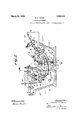
Referring now to the drawings forming part of this specification, Figure 1 is a plan showing a tinning pot constructed and arranged in accordance with my invent-ion.
It ist-his rough, 60`
i A designates a tinning pot, in itself an old edgeI of this partition 2,-which terminates of pot. v
In the accompanying drawings, the letter and approved form. The pot is separated transversely by a vertical wall orpartition 2 into compartments B and' C. The' lower above the bottom o f the tinning pot, and the upper'edge of a rib or projection 3 on the bottom of the pot define the width or vertical dimension vof a narrow opening forming a passage D through which v'the plates, while submerged inthe bath of molten tin, pass from the compartment B into the compartment C`of the pot A.
rlhe particular pot shown is of a width.
which permits of two or more plates, side by side, being passed through the tinning pot. (See Figures 1 and Obviously, when desired, a. narrower pot of a.width slightly greater than the "width of the widest plate may be used. Any of various known means may be used for heating the tinning pot and,
preferably, these means will be constructed and arranged to maintain the tin in compartment B at a considerably higher temperature than the tin in compartment C. rlhe pot heating apparatus, not formingl part of this invention, is not shown ynor further described.
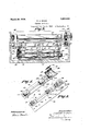
The side walls of the compartment C at I the exit end of the pot are extended upwardly so thatl this compartment is considerably deeper thanxthe compartment B, this old and well known construction making it possible to maintain a body of oil, (generally palm oil). of the requisite depth or thickness, on top of the molten tin in compartment C. The levels at which the bath of molten tin is maintained in the pot are indicated by the line X-X of Figure 2, and a layer H of flux is maintained on top of the tin in the compartment B at the entrance end of the pot. Due to the weight of the body of oil on thetin bath in the compartment C of the tin pot, the 'level of the molten.
tin in this compartment is somewhat lower than that of the tin in the compartment B. (See Figure 2.)` l
.A supporting frame O is mounted in the compartment B, and is composed of suitable side plates which extend above the top of the tin pot. A pair of transverse plates O extend between and are connected tothe side plates of the frame O so as to cooperate therewith and serve to form a flux box to confine or retain the layer of iuX H on top of the tin in the compartment B of the pot.
Located immediately above the upper edge of the compartment B, at the' plate entering side of the tinning pot, are two sets of spring pressed feed 4rollers E and `F, which are ar ranged to move the pickled and washed Aplatesforwardly and downwardly into the tin pot at an angle to the horizontal..
The set of feed rollers E, 'as shown, is formed of rollers 4 and 5, and the set of rollers F, consisting of the rollers 6 and 7 are at a somewhat lower levelthan the set E. An adjustable deflecting roller G, although not always necessary, preferably will be rovided below and'on the discharge side o the set of rollers F, to guide and direct the front end of the plates forwardly and downwardly through the flux H into the molten tin in the compartment B.
Positioned within the 'compartment B, at a point closely adjacent to thepassage D, 1s
a set of pressure rollers I formed of rollers 8 and 9. The uppenroller 9 is mounted in sliding bearing blocks 10 which have upwardly extending tension rods 11 that extend through a transverse bar 12 and through the over-hanging portion 13 of a bracket 14 on the bar 12. The roller 9 is provided midway of its length with a bearing surface 15, and a bearing shoe 16 engaging the upper porton thereof has a rod 11 by which `it is yieldingly mounted on the bar 12. The rods` 11 are provided with shoulders 17 and a coil spring 18 is mounted on each of the rods 11, a ove the shoulder 17, so that one end of the springs bears against the shoulders 17 and the other end against the overhanging ortions 13 of the brackets 14. The resi ient springs 18 serve to normallyliold the roller 9 in close contact with the roller 8.
The roller. 8 is mounted in bearing blocks 19 and is ,provided with a center bearing portion 20 which is supported by a bearing` shoe 2l mounted on a post 22, which is pivotally supported at itslower end on a bar 23, this bar being pivotally secured by one end to the frame O and having its other end pivotally connected to a link 24. The upper ,end of the link 24 passes through the bracket 25 on the frame O and` is provided with a shoulder 26 at a point below the br .cket 25, which supports the lower end of a coil spring 27 on the link, the upper end "of the s ring'27 bearing against the bracket 25. See Figure 3.) The bearing shoe 21 and its resilient mounting act to -normally force the roller 8 toward the roller compartment B into the compartmentv C of the tinning pot and at the same time flattening and smoothing the layer of iron-tin alloy that forms on the iron or steel plates or sheets as they enter the molten tin in compartment B of the tinning, pot.
lt will be noted that the sets of feed in rollers E and'F and the guide roller G are above the layer of ux H, and that the successive plates are mechanically fed and guided into, through and out of the tinning pot. This mechanical feed is important, since it permits the 4plates to be fed s'uccessively and interruptedly through the flux at the same speed as they are fed through the tin.
The location of the pressure rollers l with respect to the layer of flux H is to be particularly noted, because it has heretofore been considered impossible to use submerged rollers in a tinning machine. This is because. experience shows that long contact of the rollers With the molten tin bath causes the layer of tin.on the rollers to flake off and bare the surface of the rollers, and Asuch occurrence results in making 'defectively coated plates, known in the art as having black spots or plates having uneoated spots on the surfaces thereof.
I have found. that by positioning the rollers I so that vthe distance from the flux H is nottoo great and by feeding the plates at a constant and fairly high speed, venough flux will be carried dovvn on the surfaces of the plates and the flux will be carried so uniformly on such surfaces as to maintain the rollers l in uniformly good lworking condition. lAlso, I propose to use a single set of rollers submerged in the tin bath because it is not practicable to use two or more suchsets in succession and still carry the iiux uniformly to the second or later set and in 4such quantityas to prevent the production of plates with black spots.
ln the construction of Figures 2 and 3,
. sets of feed-out rollers J and K are provided, which are located within the body of oil maintained on top of the tin bath in compartment@ of the pot A. The pair of rollers 30, 3l forming the set J, and the rollers 32, 33 forming the set K, are-arranged to not only feed the plates out of the tin pot but also act to 4squeeze off surplus tin from the smooth, tin coated surfaces of the plates as the plates pass upwardly through the oil bath out of the tinning pot. The body of oil, in which the feed-out rollers are submerged, acts to prevent the molten coating on thesurfaces of the plates from contacting with the atmosphere until after the excess coating has been removed therefrom.
lt will be noted that, the sets of rollers E, F, and J are relatively positioned or lapaeed so that the front end of the plates Y Will be engaged in the bite of a succeeding set of rollers before the rear end emerges from between the rollers of the preceding set. `That is to sayhthe rollers are so positioned that the distance the plates must travel from one set of rollers to the next set is less than the length of the plates. It will also be seen by reference to Figure of the drawings that the set of rollers I is the only one submerged in the tin bath.
An inclined apron 34 at the entrance end of the compartment B of the pot, receives the plates as they are delivered to the tinning pot. The plates and 3G form a guide L for directing the front end of successive plates into the bite of the set-of rollers F -as it emerges from between theset of rollers E.
Curvedplates 37 and 33 forming a guide M are positioned within the compartment B so as to direct the forward end of the plates being tinned into the nip of the set of pressure feed rollers l, as is clearly shown in Figure 2. rlhese guide plates 37 and 38 preferably are of skeleton form, so as not to interfere with scr-uff and dross or other foreign material in the molten tin settling to the bottom of the pot.
T he framework O, which supports the sets` of feed rollers E and F, guide rollers G and pressure rollers I, and the stationaryI guides L and M, is removably secured within the compartment B so as to permit the feed-in apparatus to be bodily removed from thepot while the tin bath is molten. This is done at inter-vals in order to clean the tinning pot Vand 1to make necessary repairs to the feed-in apparatus. The sets of feed-out rollers J and K and guide N are mounted in a similar manner on the framework P in the compartment C ofthe pot and can be taken out of and replaced in the compartment C in the same manner as the apparatus within the other compartment B.
The feed rollers 4 and 5 of the set E are connected by a pair of spur gears 42 so that both of these rollers are positively driven, and the rollers 6 and 7 of the set F are likewise connected by spur gears 43. The rollers 8 and 9 forming the submerged set i are also connected by spur gears 44 so es to be positively rotated. f
The rollers 30, 3l forming the set J. are connected by spur gears 45 so as to be positively rotated, and the rollers 32 and 33 and roller 8 of the pressure feed rollers are the driven members of their respective sets. The feed roller 4 is providedwith a spur gear 47 which meshes with the spur gear 48 on the stub shaft 49 which is journaled lin the frame O, this shaft having a drive sprocket 50 driven by a chain from a suitable motor (not shown). A drive .shaft 51 is journaled in suitable bearings 52, these bearings being mounted on an angle support 53 fastened to one side `of the frame O. Each of the rollers 4 and 6 and roller 8 is provided with bevel gears 54 which mesh with bevel gears 55 on the shaft 51. l
The rollers'30, 3l and 32, 33 forming the sets of feed-out rollers J and K, respectively, are driven by a sprocket wheel 56 which is mounted on an extension of the shaft of the roller 32. The roller 32 is also provided with a spur gear 57 which meshes with` a` spur gear 5.8 on the roller 31.
The gears and other drive mechanism for the sets of feed-in rollers E and F, feed pressure rollers I and feed-out rollers J and K are arranged sov that each individual roller is positively driven at a uniform surface speed of at least 120 and up to 1504 -inches per minute, thereby providing for feeding plates into',through, and out of the;
tinning machine at a uni orm and relatively high speed.
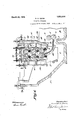
The exit or feed-out side of the slightly modified form of tinning machine shown in Figure 6 is the same as that of Figures 2 and 3, excepting that in the machine of Fig-y ure 6 the compartment C is made slightly deeper and is provided with three sets of feed-out rollers R, S, and T formed of the rollers 59 and 60, 61 and 62, and 63 and 64, respectively. y
' The roller 64 ofthe set T is positively driven from a source of power (not shown), and is provided with a spur gear which meshes with a spur gear 66 on Athe roller 6l of the set S, and thev gear 66 meshes withv a spur gear 67 on the roller 60 of the set R, so that all of the rollers are positively driven. The third set of feed-out rollers in the modified apparatus of Figure 6 serves, like the other two sets, to squeeze more of the molten tin from the plates as they pass -g'upwardly through theoil in the compartment C.
In carrying out my method of making tin plate is thereafter mechanically fed forward through the guide L into the nip of the second pair of feed rollers F, which are loy cated immediately above the layer of flux H in the flux box. In passing from between the rollers F, the plate is directed into the flux H by the guide roller G, so that at notime does it come into Contact with anyA extension or guide pro]ect1ng.below orbeyond I the level of the flux. The provision of means for entering the sheets into the tin bath through the luxvwithout having the plates come into contact with any stationary part of the pot avoids dislodgment of flux and other substances previously depositedfon the plate and which desirably should be carried down .tol the pressure feed rollers I. The
uniform rate of movement of the plate into and through the flux and tin bath also aids .in causing a sufficient uantity of flux -to be carried down to the ro lers I, to keep these rollers in proper working condition. Heret'ofore,vwith the well known hand-feed apparatus the plates are first moved through the flux very fast and then at a comparatively slower rate of speed through the tin bath, with the result that the `plates are not sufficiently 'liuxed and poorly coated plates being produced. Y
After passing through the flux, the plate enters the molten tin" in thecompartment B, passing through the curved guide M which delivers the plate into the nip of the pressure feed rollers .I. l As the plate passes through the tin bath in the compartment B an iron-tin alloy coating is formed on the surfaces thereof, and as it passes between the pressure feed rollers I the coating is compressed and flattened, and surplus tin4 is sequeezed off and removed from the alloy coating on the plate. The
plate, having an iron-tin alloy coating, then passes through the opening D and is deflected by the curved guide N upwardly through the bath of tin in the compartment C and into the nip of the first pair of feedout rollers J which are in the oil bath above and supported upon the tin in the compartment C.
As the plate passes between the feed-out rollers of the sets J and K, any excess tin adhering to the surfaces of the plate is re- 4moved by the pressure of these rollers and a finished plate is produced having an outer layer of substantially-pure tin which has the luster and other properties and characteristics of the heavy coating of charcoal plates.
As has' been said before, all of the rollers of the several sets in the machine are positively driven at a substantially uniform and relatively high surface speed and, therefore, the plates are fed through the machine at a uniform speed. This, together with the other novel features of the machine, permits the plates to be fed into, through, and out of the tinning apparatus at a speed of from 120 to 150 inches or even more p er minute, Without increasing the yield and in some cases, With an A actual decrease in the yield, such speeds being considerably higher than is possible Without an increase in yield, with the tinning apparatus heretofore used. l
While a specific embodiment of my invention has been described herein, it will be vother below the top of the tin bath, means in one compartment for maintaining a body of` iiux on top of the tin bath, means in the other compartment for maintaining an oil bath on top of the tin bath, a feeding mechanism above the iuX to feed the plates into and through the flux into the tin bath, an intermediate feed mechainsm to feed said plates through the tin bath into the oil bath, said intermediate mechanism comprising a single pair of rollers setin the tin bath close to the iiux so that the ux is carried rapidly and at a uniform rate to said rollers, and a feedout mechanism in the oil. bath to feed the tinned plates out of the oil bath, said feed mechanisms being operatively connected to successively and uninterruptedly feed' plates into, through and out of the flux, tin bath and oil bath at a relatively high and substantially equal and uniform speed.
2. Tinning apparatus comprising a tinning pot having compartments for the molten .tinbath' commuicating with each. other below the top` of the tin bath', means in one compartment for maintaining a body of iiux on top of the tin bath, means 1n the other compartment for maintaining an.o1l
bath on top of the tin bath, a feeding mechanism above the flux to feed the plates into and through the iiux into the tin bath, an intermediate feed mechanism onthe uX side of the tinning pot to feed said plates through the tin bath into the oil bath, said i termediate mechanism comprising a single -pair of rollers and a feed-out mechanism in the oil bath to feed the tinned plates out of the oil bath, said feed-in and feed-through mechanisms being directly and unyieldingly connected to a common driving mechanism adapted to operate them at a relatively high and equal and uniform speed.
3. Tinning apparatus comprising atinningfr pot having compartments for the molten tin bathjcommunicating with each other below the top of the tin bath, means in one compartment for .maintaining a body of iiux on top of the t-in bath, a feeding mechanism above the flux to feed the plates into and through the flux into the tin bath, an intermediate feed mechanism on theliux sida."
of the tinning pot to feed said plates through the tin bath into the oil bath, said intermediate mechanism comprising a single pair of rollers and 'a feed-out mechanism in the'oil bath to feed the tinned plates out of the oil bath, and driving mechanism positively and unyieldingly connected to said three feeding mechanisms .and adapted to drive them at a relatively high and equal and uniform surface speed.
In testimony whereof I have hereunto set my hand.t
STEWART A. Davis
Priority Applications (1)
| Application Number | Priority Date | Filing Date | Title |
|---|---|---|---|
| US756742A US1663444A (en) | 1919-06-25 | 1924-12-18 | Tinning apparatus |
Applications Claiming Priority (2)
| Application Number | Priority Date | Filing Date | Title |
|---|---|---|---|
| US306521A US1528407A (en) | 1919-06-25 | 1919-06-25 | Manufacture of tin plate |
| US756742A US1663444A (en) | 1919-06-25 | 1924-12-18 | Tinning apparatus |
Publications (1)
| Publication Number | Publication Date |
|---|---|
| US1663444A true US1663444A (en) | 1928-03-20 |
Family
ID=26975217
Family Applications (1)
| Application Number | Title | Priority Date | Filing Date |
|---|---|---|---|
| US756742A Expired - Lifetime US1663444A (en) | 1919-06-25 | 1924-12-18 | Tinning apparatus |
Country Status (1)
| Country | Link |
|---|---|
| US (1) | US1663444A (en) |
Cited By (1)
| Publication number | Priority date | Publication date | Assignee | Title |
|---|---|---|---|---|
| US5072689A (en) * | 1988-06-15 | 1991-12-17 | Hitachi, Ltd. | Continuous hot-dip plating apparatus |
-
1924
- 1924-12-18 US US756742A patent/US1663444A/en not_active Expired - Lifetime
Cited By (1)
| Publication number | Priority date | Publication date | Assignee | Title |
|---|---|---|---|---|
| US5072689A (en) * | 1988-06-15 | 1991-12-17 | Hitachi, Ltd. | Continuous hot-dip plating apparatus |
Similar Documents
| Publication | Publication Date | Title |
|---|---|---|
| US1663444A (en) | Tinning apparatus | |
| US3738861A (en) | Method of wiping galvanised wire or strip | |
| US3460512A (en) | Apparatus for depositing a solder strip on a base metal band | |
| US1663445A (en) | Tin plate | |
| US2878171A (en) | Method of manufacturing abrasive surfaces by electro formation and the products obtained thereby | |
| GB1481000A (en) | Aluminium plating methods and coating alloy for use therein | |
| US2075331A (en) | Method and apparatus for the electrodeposition of metal | |
| FR2568271A1 (en) | PROCESS FOR THE ELECTRODEPOSITION OF CONTINUOUS METALS, AT HIGH CURRENT DENSITY, IN VERTICAL CELLS AND DEVICE FOR EXECUTING THE PROCESS | |
| US1734737A (en) | Method of and apparatus for coating strand material | |
| US1810699A (en) | Method of and apparatus for the manufacture of tin plate | |
| US2267877A (en) | Apparatus for the manufacture of tin plate | |
| US1672526A (en) | Metal-coating machine | |
| US1755559A (en) | Galvanizing | |
| US4239817A (en) | Process and apparatus for coating one side of a metal strip with molten metal | |
| US2332946A (en) | Apparatus for manufacturing phonographic disks | |
| US1528407A (en) | Manufacture of tin plate | |
| US2075332A (en) | Apparatus for the electrodeposition of metal | |
| US1608644A (en) | Method of and apparatus for forming sheet glass | |
| US1862249A (en) | Process and apparatus for coating ferric articles with a. metallic protective | |
| US1669975A (en) | Metal-coating machine | |
| US1469316A (en) | Candy-making machine | |
| US1783575A (en) | Apparatus for coating roofing units | |
| US1971220A (en) | Galvanizing machine | |
| US1732504A (en) | Method and apparatus for coating | |
| US2037503A (en) | Machine for coating metal plates with metals or alloys |