US1663302A - Mark hehzl - Google Patents
Mark hehzl Download PDFInfo
- Publication number
- US1663302A US1663302A US1663302DA US1663302A US 1663302 A US1663302 A US 1663302A US 1663302D A US1663302D A US 1663302DA US 1663302 A US1663302 A US 1663302A
- Authority
- US
- United States
- Prior art keywords
- mark
- aeroplane
- bell
- power system
- propeller
- Prior art date
- Legal status (The legal status is an assumption and is not a legal conclusion. Google has not performed a legal analysis and makes no representation as to the accuracy of the status listed.)
- Expired - Lifetime
Links
- 238000010304 firing Methods 0.000 description 9
- 238000010276 construction Methods 0.000 description 6
- 238000002485 combustion reaction Methods 0.000 description 4
- 239000002360 explosive Substances 0.000 description 3
- 239000007789 gas Substances 0.000 description 3
- 230000037431 insertion Effects 0.000 description 2
- 238000003780 insertion Methods 0.000 description 2
- 239000000126 substance Substances 0.000 description 2
- 238000004880 explosion Methods 0.000 description 1
- 239000003721 gunpowder Substances 0.000 description 1
- 239000000463 material Substances 0.000 description 1
- 239000000843 powder Substances 0.000 description 1
- 239000007787 solid Substances 0.000 description 1
Images
Classifications
-
- B—PERFORMING OPERATIONS; TRANSPORTING
- B64—AIRCRAFT; AVIATION; COSMONAUTICS
- B64C—AEROPLANES; HELICOPTERS
- B64C23/00—Influencing air flow over aircraft surfaces, not otherwise provided for
- B64C23/005—Influencing air flow over aircraft surfaces, not otherwise provided for by other means not covered by groups B64C23/02 - B64C23/08, e.g. by electric charges, magnetic panels, piezoelectric elements, static charges or ultrasounds
-
- Y—GENERAL TAGGING OF NEW TECHNOLOGICAL DEVELOPMENTS; GENERAL TAGGING OF CROSS-SECTIONAL TECHNOLOGIES SPANNING OVER SEVERAL SECTIONS OF THE IPC; TECHNICAL SUBJECTS COVERED BY FORMER USPC CROSS-REFERENCE ART COLLECTIONS [XRACs] AND DIGESTS
- Y10—TECHNICAL SUBJECTS COVERED BY FORMER USPC
- Y10S—TECHNICAL SUBJECTS COVERED BY FORMER USPC CROSS-REFERENCE ART COLLECTIONS [XRACs] AND DIGESTS
- Y10S60/00—Power plants
- Y10S60/914—Explosive
Definitions
- the present invention relates to improvements in aerial Vessels, and more part1cularly to an auxiliary power system therefor.
- the main object of the invention is to provide an aerial vessel, provided, in addition to the motor-driven propeller or propellers, with one or more propellers which are driven independently of the motor of the aerial vessel, more particularly by a rotary internal combustion engine in which a charge of gun powder or other explosive substance 1s exploded and the resulting gases allowed to I act upon the working piston of the engine.
- Another object of the invention is to provide an auxiliary power system of the charactor described which is simple in construc tion, efficient in operation, and which may be conveniently installed in aerial vessels Without necessitating material changes in the construction of the latter.
- a further object of the invention is to produce an auxiliary power system of the character mentioned, which, when applied to aeroplanes, will sustain the same in flight for a considerable time even after the main motor thereof comes to a full stop, thereby avoiding accidents due to the sudden stoppage of the said motor.
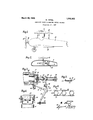
- igure 1 is a side elevation of the front portion of an aeroplane, provided with ,an auxiliary power system constructed in accordance with the present invention
- Fig. 2 is a transverse section taken through one of the aerofoils of the aeroplane, on a larger scale, showing in elevation the auxiliary power system
- Fig. 3 is a central vertical section, partly in elevation, taken through the firing device of the power system
- Fig. 4 is a side elevation of a portion of said firing device
- Fig. 5 is a section taken through one of the cartridges used in the internal-com- I bustion motor
- Fig, 6 is a plan view of a band of the cartridges.
- the numeral 10 indicates an aeroplane, which may be of any suitable type and construction.
- the said aeroplane includes an upperaerofoil 11, a lower aerofoil 12, and a screw propeller 13 mounted on a horizontal shaft 14, the said shaft being driven by a power plant, not shown.
- the construction and operation of the elements are well known, so that a further detailed description thereof seems to be unnecessary.
- the auxiliary power plant comprises a rotary internal combustion engine 15 of any suitable type, preferably mounted within. the upper aerofoil 11, and provided with a vertical driven shaft 16, to which is attached an auxiliary propeller 17, disposed above the aerofoil 11.
- This motor is, preferably, of the turbine type, its runner being actuated by charges of un powder of other explosive substances, w ich are exploded within a chamber 18, provided with a, nozzle 19, the latter directing the resultant gases to the said runner which is thus rotated, thereby actuating the auxiliary propeller 17.
- this head On diagonally opposite portions of this head are provided apertures 22, to allow of the insertion of cartridges, as will hereinafter appear, said apertures being adapted to be closed by a cap 23, which is slidably arranged on the said head, springs 24 being adapted to keep the said can in its outer position in which the said apertures are open, as clearly shown in Fig. 4 of the drawings.
- the head and cap are provided with registering openings 25 and 26, respectively, through which a firing pin 27 is adapted to protude.
- This pin slides in guides 28 and carries a collar 29, adapted to bear against the outer face of the cap 23.
- On'the pin is provided a further collar 30, between which and one of the guides 28 is inserted an actuating spring 31.
- the cartridges consist each of a shallow ,open container 32, having projections 33.
- the cartridges are supplied to the chamber 18 through the apertures 22, by a bell-crank lever 37, which is fulcrumed at 37' adjacent the said chamber.
- the arm 38 of this bell-crank lever is in engagement with a flexible means 39 such as a cord, which leads over a sheave 40 down to within reach of the operator on a seat on the body of the aeroplane.
- the other arm 41 of the said bell-crank lever is. adapted to engage projections 33 on the cartridges, drawing them, in a manner hereinafter to be described, through the apertures 22 above mentioned to an abutment 42, which is carried by the head 21.
- the bell-crank lever Adjacent its fulcrum, the bell-crank lever is provided with a finger 43, adapted to engage a lug 44 of a lever 45, which is fulcrumed at 46 adjacent the firing pin and engages a recess 47 in said firing pin.
- this device is as follows: Normally the aeroplane is propelled through the air by the main propcller'l3.- The auxiliary propeller 17 is then at rest and the elements ofthe cartridge supplying and firing pin setting device and also the firing pin are in the positions shown in Fig. 3 of the drawings. In these positions the arm 41 of the bell-crank lever 37 engages an already fired cartridge, that is in contact with the abutment 42. If the main power plant of the propeller, by accident or otherwise, comes to a full stop, the rotary'internal combustion engine 15 is set to motion. For this purpose, the operator takes hold of the cord 39 and pulls the same in the direction of the arrow shown in Fig. 1 of the drawings, whereby the finger 43 of the bell-crank lever engages the lug 44 of the ever 45,
- bell-crank lever 37 supplies a new cartridge to the chamber by engaging the already fired cartridge, in contact with the abutment 42, and'drawing the said cartridge downwards, whereby a new cartridge is inserted into the chamber 18.
- the finger 43 is disengaged from the lug 44, the spring 31 is allowed to act, whereby the firing pin is projected into the chamber cord 39, the auxiliary propeller is kept in,
- An auxiliary propelling mechanism for aeroplanes including arotary internal combustion engine having a vertical driven shaft extending through the top aerofoil of the aeroplane, a propeller attached to said shaft above said aerofoil rotatable in a horizontal plane, means associated with said engine for exploding solid explosivecharges and permitting the resulting gases to act upon the rotor of said engine, and means within the reach of the operators'seat in the body of said aeroplane forfeeding explosive charges to said first-mentioned means and for actuating the charge explosion means.
Landscapes
- Engineering & Computer Science (AREA)
- Aviation & Aerospace Engineering (AREA)
- Toys (AREA)
Description
M. HERZL AUXILIARY POWER SYSTEM FOR AERIAL VESSELS Filed 061;. 27. 1927 Mim A r I III/ IN V EN TOR.
ATTORN s.
Patented Mar. 20, 1928.
UNITED STATES MARK HERZL, OF NEW YORK, N. Y.
AUXILIARY POWER SYSTEM FOR AERIAL VESSELS.
Application filed October 27, 1927. Serial No. 229,126.
The present invention relates to improvements in aerial Vessels, and more part1cularly to an auxiliary power system therefor.
The main object of the invention is to provide an aerial vessel, provided, in addition to the motor-driven propeller or propellers, with one or more propellers which are driven independently of the motor of the aerial vessel, more particularly by a rotary internal combustion engine in which a charge of gun powder or other explosive substance 1s exploded and the resulting gases allowed to I act upon the working piston of the engine.
Another object of the invention is to provide an auxiliary power system of the charactor described which is simple in construc tion, efficient in operation, and which may be conveniently installed in aerial vessels Without necessitating material changes in the construction of the latter.
A further object of the invention is to produce an auxiliary power system of the character mentioned, which, when applied to aeroplanes, will sustain the same in flight for a considerable time even after the main motor thereof comes to a full stop, thereby avoiding accidents due to the sudden stoppage of the said motor.
With these and other objects in View, which will more fully appear as the nature of the invention is better understood, the same consists in the combination, arrangement and construction of parts hereinafter described, pointed out in the appended claim and illustrated in the accompanying drawings, it being understood that many changes may be made in the size and proportion of the several parts and details of construction within the scope of the appended claim, without departing from the spirit or sacrificing any of the advantages of the invention.
One of the many possible embodiments of the invention is illustrated in the accompanying drawings, in which igure 1 is a side elevation of the front portion of an aeroplane, provided with ,an auxiliary power system constructed in accordance with the present invention; Fig. 2 is a transverse section taken through one of the aerofoils of the aeroplane, on a larger scale, showing in elevation the auxiliary power system; Fig. 3 is a central vertical section, partly in elevation, taken through the firing device of the power system; Fig. 4 is a side elevation of a portion of said firing device; Fig. 5 is a section taken through one of the cartridges used in the internal-com- I bustion motor; and Fig, 6 is a plan view of a band of the cartridges.
In the drawings, the numeral 10 indicates an aeroplane, which may be of any suitable type and construction. In the case illustrat ed the said aeroplane includes an upperaerofoil 11, a lower aerofoil 12, and a screw propeller 13 mounted on a horizontal shaft 14, the said shaft being driven by a power plant, not shown. The construction and operation of the elements are well known, so that a further detailed description thereof seems to be unnecessary.
The auxiliary power plant comprises a rotary internal combustion engine 15 of any suitable type, preferably mounted within. the upper aerofoil 11, and provided with a vertical driven shaft 16, to which is attached an auxiliary propeller 17, disposed above the aerofoil 11. This motor is, preferably, of the turbine type, its runner being actuated by charges of un powder of other explosive substances, w ich are exploded within a chamber 18, provided with a, nozzle 19, the latter directing the resultant gases to the said runner which is thus rotated, thereby actuating the auxiliary propeller 17. The
On diagonally opposite portions of this head are provided apertures 22, to allow of the insertion of cartridges, as will hereinafter appear, said apertures being adapted to be closed by a cap 23, which is slidably arranged on the said head, springs 24 being adapted to keep the said can in its outer position in which the said apertures are open, as clearly shown in Fig. 4 of the drawings. The head and cap are provided with registering openings 25 and 26, respectively, through which a firing pin 27 is adapted to protude. This pin. slides in guides 28 and carries a collar 29, adapted to bear against the outer face of the cap 23. On'the pin is provided a further collar 30, between which and one of the guides 28 is inserted an actuating spring 31.
The cartridges consist each of a shallow ,open container 32, having projections 33.
33. The cartridges are supplied to the chamber 18 through the apertures 22, by a bell-crank lever 37, which is fulcrumed at 37' adjacent the said chamber. The arm 38 of this bell-crank lever is in engagement with a flexible means 39 such as a cord, which leads over a sheave 40 down to within reach of the operator on a seat on the body of the aeroplane. The other arm 41 of the said bell-crank lever is. adapted to engage projections 33 on the cartridges, drawing them, in a manner hereinafter to be described, through the apertures 22 above mentioned to an abutment 42, which is carried by the head 21. Adjacent its fulcrum, the bell-crank lever is provided with a finger 43, adapted to engage a lug 44 of a lever 45, which is fulcrumed at 46 adjacent the firing pin and engages a recess 47 in said firing pin.
The operation of this device is as follows: Normally the aeroplane is propelled through the air by the main propcller'l3.- The auxiliary propeller 17 is then at rest and the elements ofthe cartridge supplying and firing pin setting device and also the firing pin are in the positions shown in Fig. 3 of the drawings. In these positions the arm 41 of the bell-crank lever 37 engages an already fired cartridge, that is in contact with the abutment 42. If the main power plant of the propeller, by accident or otherwise, comes to a full stop, the rotary'internal combustion engine 15 is set to motion. For this purpose, the operator takes hold of the cord 39 and pulls the same in the direction of the arrow shown in Fig. 1 of the drawings, whereby the finger 43 of the bell-crank lever engages the lug 44 of the ever 45,
whereby compressing the spring31 of the firing pin 27. At the same time thecap 23,-
under the tension of the springs 24, moves outwards, thereby allowing of the insertion of a new cartridge into the chamber 18. As
soon as the apertures 22 are uncovered, the
bell-crank lever 37 supplies a new cartridge to the chamber by engaging the already fired cartridge, in contact with the abutment 42, and'drawing the said cartridge downwards, whereby a new cartridge is inserted into the chamber 18. When now, in the further swinging movement of the bell-crank lever 37, the finger 43 is disengaged from the lug 44, the spring 31 is allowed to act, whereby the firing pin is projected into the chamber cord 39, the auxiliary propeller is kept in,
motion until a safe landing is made.
What I claim is An auxiliary propelling mechanism for aeroplanes, including arotary internal combustion engine having a vertical driven shaft extending through the top aerofoil of the aeroplane, a propeller attached to said shaft above said aerofoil rotatable in a horizontal plane, means associated with said engine for exploding solid explosivecharges and permitting the resulting gases to act upon the rotor of said engine, and means within the reach of the operators'seat in the body of said aeroplane forfeeding explosive charges to said first-mentioned means and for actuating the charge explosion means.
Signed at New York, in the county of New York, and State of New York, this 22nd day of September, A. D. 1927.
MARK HERZL.
Publications (1)
| Publication Number | Publication Date |
|---|---|
| US1663302A true US1663302A (en) | 1928-03-20 |
Family
ID=3414735
Family Applications (1)
| Application Number | Title | Priority Date | Filing Date |
|---|---|---|---|
| US1663302D Expired - Lifetime US1663302A (en) | Mark hehzl |
Country Status (1)
| Country | Link |
|---|---|
| US (1) | US1663302A (en) |
-
0
- US US1663302D patent/US1663302A/en not_active Expired - Lifetime
Similar Documents
| Publication | Publication Date | Title |
|---|---|---|
| US3023980A (en) | Turbo-fan lift device | |
| US2898893A (en) | Impact tool | |
| US2479713A (en) | Canopy control and jettisoning mechanism | |
| US2466980A (en) | Missile ejector for aircraft | |
| US3622108A (en) | Safety device for disabled airplanes | |
| US3487445A (en) | Power actuated gyro controlled ejection seat stabilizing system | |
| US2693326A (en) | Ejectable seat for aircraft | |
| US2553253A (en) | Jet propulsion engine | |
| US1663302A (en) | Mark hehzl | |
| US3233548A (en) | Dirigible aerial torpedo | |
| GB1174464A (en) | Device for Preventing Rotation of an Object in Space. | |
| US2445235A (en) | Aircraft with blast or like tube and closure therefor | |
| US4052927A (en) | Autorotor launching system | |
| US3158100A (en) | Rocket propelled reconnaissance vehicle | |
| US3424409A (en) | Occupant escape apparatus for an aircraft or the like | |
| US3186662A (en) | Ejection of one body from another | |
| US2924403A (en) | Actuator device | |
| US2937830A (en) | Ejecting device for aircraft | |
| US3013493A (en) | Aerial flare | |
| US2998213A (en) | Ejection seat | |
| GB1420689A (en) | Rocket actuated escape apparatus | |
| US1621421A (en) | Apparatus for lighting the landing place from aerial craft | |
| RU2090454C1 (en) | Saucer-type flying vehicle for planetary and interplanetary navigation | |
| US2469660A (en) | Control of variable pitch airscrews for aircraft | |
| US1838984A (en) | Rocket motor aeroplane |