US1663296A - Locked closure for tank openings - Google Patents
Locked closure for tank openings Download PDFInfo
- Publication number
- US1663296A US1663296A US110338A US11033826A US1663296A US 1663296 A US1663296 A US 1663296A US 110338 A US110338 A US 110338A US 11033826 A US11033826 A US 11033826A US 1663296 A US1663296 A US 1663296A
- Authority
- US
- United States
- Prior art keywords
- wall
- cap
- aperture
- tank
- bolt
- Prior art date
- Legal status (The legal status is an assumption and is not a legal conclusion. Google has not performed a legal analysis and makes no representation as to the accuracy of the status listed.)
- Expired - Lifetime
Links
Images
Classifications
-
- B—PERFORMING OPERATIONS; TRANSPORTING
- B65—CONVEYING; PACKING; STORING; HANDLING THIN OR FILAMENTARY MATERIAL
- B65D—CONTAINERS FOR STORAGE OR TRANSPORT OF ARTICLES OR MATERIALS, e.g. BAGS, BARRELS, BOTTLES, BOXES, CANS, CARTONS, CRATES, DRUMS, JARS, TANKS, HOPPERS, FORWARDING CONTAINERS; ACCESSORIES, CLOSURES, OR FITTINGS THEREFOR; PACKAGING ELEMENTS; PACKAGES
- B65D90/00—Component parts, details or accessories for large containers
- B65D90/54—Gates or closures
Description
J. H. FALSTER March 20, 1928. 1,663,296
LOCKED CLOSURE FOR TANK OPENINGS Filed May 20, 1926 INVENTOR. @197) H, 5% 722? M3 maw ATTORNEY Patented Mar. 20, 19 28.
UNITED STATES 1,663,296 PATENT OFFICE.
JOHN H. FALSTER, OF OAKLAND, CALIFORNIA.
LOCKED CLOSURE FOR TANK-OPENINGS.
application filed May 20,
comparatively large and must beTcovered' W with a capping closure, the problem resolves itself into providing means for locking, the closure in position and which are at. the same time readily releasable by an author ized person. Furthermore, the means must l be simple in structurefand operation, and
" readily applicable tofexisting tanks. 'The foregoing requirements have {been met in the device of my invention and it- .is accordingly one object of the invention to pro-.
vide a device of the character described whichma-y be applied to containers of usual structure without requiring the alterationthereot,
Another object of the invention is to provide locking units of the character described so arranged that a single unit thereof may be used on a variety of tanks, thus providing forthe substantially universal use of? the device in a single size and design.
A .further object of the invention is to provide a device ofthe character described which is ofextremely simple structure and may be manufactured at a minimum'cost.
The invention possesses other objects and features of advantage,-some of which,,with
the. foregoing, will bev set forth in the followingdescription of the preferred form of my inventionwhich is illustrated in the draw-, ings accompanying and forming partof the. specification. I It is to be understood that-l do not limit myselfto the showing made by thewsaid drawings and description, as In ay adopt variations of the preferred formwithin the scope of-my invent-ion as set, forth. inthe claims. v y
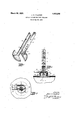
Referring tosaid drawingsi y i Figure l is a perspective viewrshowing cooperating members of the device in slight ly spaced relation. g
Fi ure 2 is a vertical sectional view showingthe deviceoperatively disposed to effect the locked closure of a tank filler opening. Figure 3 is a sectional view takenon the line 3-3 in Figure 2. As illustrated in thedrawings, the device of my invention comprises a member 4 hav- 1926. Serial No. 110,338.
ing a cylindrical stem portion 5 and a base portion 6. r g
As here shown, the portion 6 is cylindrical about a common axis with the portion, 5 and is of somewhat greater diameter than is the filler opening 7 of the tank8, while the stem portion 5 is of somewhat less diameter than is the opening 7 The stem 5 it will now be noted, is provided with a number of transverseperforationsv 9 along its length, such perforations being arranged to receive the bolt 11 of a suitable lock 12, the latter being here shown as a: padlock of a usual type.
Toprovide for the insertion of the device through the filler opening,.the member 4 is preferably formed in transversely separable sections. As here shown, the, member A comprises a pair of cooperating like sections,
13 and 14k having their plane of separation include the axis of'the member 4,-it being noted that the perforations 9 extend transversely of suchplane.
7. one at a time, it being noted that the section first placed in the opening may be held to one side thereof to permit the insertion of the other section, after which the sections maybe placed together with their flat back surfaces 15 together. i
The tank cap 16, it will now benoted, is provided with a perforation 17 arranged to freely receive the stem 5 when the sections arein cooperative relation. Inv this manner, with the memberftpositioned .in'the opening 7 having the base portion 6 thereof disposed belowthe adjacent wall 18 of the tank and the stem portion/5 extending. from the tank, and with the sections held together, the cap Jlfimaywthen be passed downwardly alongthe stem to efi'ectla closure of the opening 7. I 4 1 j lVith the member l preferably drawn up-j wardly 'as'1'fa1- as possible, the lock bolt 11 is thenpassedthrough the lowermost free. stem perforation 9 'andlocked therein, In
p In this manner, the sections may be passed through the opening this manner, the i pward displacement of i the cap is prevented and unauthorized ac;
cess' to the opening 7 thus positively denied. I a U i As. herewith, particularly illustrated, the cap 16 is arranged for "threaded "engagement with an externally threaded flange 19 defining the o ening 7, so that, after the device is lockec, the partial unscrewing of the cap will cause it to exert a thrust against the cap comprising a unitary member having'a.
lock bolt and thus force the portion 6 of" the device against the wall 18" to therebyfix the various engaged members against relative motion and so prevent rattling of the" device, it being obvious, however, that other means might be used to prevent such rattling.
Means are provided to' facilitate the-holding of the device prior to the positioning'of the lock, and to insure the proper registration of the parts of the bolt receiving per forations. As here shown, such means comprises the provision of a socketv 21 in one of the surfaces I5 in which a projection 22 which protrudes from the" other surtace I5 is arranged to register when. the sections are properly related, the projection 22 being here shown provided by means of a pin fixed in the latter surface.
In order to insure the usually desirable venting of the tank the cap opening 17 is preferably large enough to permit the passage of gas tlierethrougli when the stem 5 is disposed therein, while the upper surface of. the base 6 is provided with one or more radial grooves 23 through which the gas may pass when the base is engaged with the tank wall 18.
It will now be particularly noted that the device of my inventionis so designed that the two sections thereof may be cast in the same mold, and that a minimum of labor is involved in preparing them: for use, so that the device will be inexpensive to manufacture.
I claim:
1. In combination with a tank having a wall provided with an aperture, a lock having a bolt, a screw cap' providing a closure member for said aperture, and a locking member passing through said aperture and closure member arranged to bear on the inner face of said wall and to receive said lock bolt at a point thereof above said closure member whereby. a releasing movement of said cap will efi'ect a forcible engagement of said member with the inner wall face and the displacement of said latter member to uncover said aperture may be prevented.
2'. In combination with a wall provided with an aperture and a removable cap-therefor, a lock bolt,. and locking means for said wall engaging. portion engageable against a side of the wall and a stem portion disposed through said aperture and cap to extend transversely outwardly of the other side of the wall, said stem portion being provided with a plurality of bolt receiving perforations longitudinally along the stem whereby side of the wall and a stem portion disposed through said" aperture and, cap to extend transversely outwardly of the other wall side and the cap, said stem portion being pro vided' with a bolt receiving perforation ar ranged to receivesaid bolt at a point closelyadjacent and outwardly ofsaid cap whereby an unscrewing rotation of said cap will act through. said'bolt and stem, to eilect a pressure engagement of said wall engaging portion withthe wall.
4. In combination with atank provided with an aperture in a wall thereof, a closure member for: said aperture arranged for threaded engagement with said wall, and a bolt; a locking bar removably positionable to extend transversely through said aperture and said closure member comprising a base portion arranged to engage the inner surface of said wall, and a stem portion arranged to receive said bolt outwardly of and substantially against said closure member whereby a releasing rotation of. said member will effect a forcible engagement oft-he baseportion of said bar with the opposed wall surface and said closure member may be held fixed against removal from said wall.
5. In combination with a tank provided with. an aperture in a wall thereof, a closure member for said aperture disposable in aplurality of' operative positions with respect to said aperture, and a bolt; a locking bar removably positionable to extend transversely through said aperture and said closure member comprising a base portion arranged to engage the inner surface of said wall, and a stem portion'arranged to receive said bolt outwardly of and substantially against said closurememberwhen in a prizmary operative positionwhereby adisposal of said closure member out of said primary position will effect a forcible engagement of the base portion of said bar with the opposed wall surface and said closure member may:
be held fixed against removal from said wall.
In testimony whereof, I have hereunto set my hand at (lalifornia, this l-Oth'day of May 1926.
JOHN H. FALSTEB.
Priority Applications (1)
| Application Number | Priority Date | Filing Date | Title |
|---|---|---|---|
| US110338A US1663296A (en) | 1926-05-20 | 1926-05-20 | Locked closure for tank openings |
Applications Claiming Priority (1)
| Application Number | Priority Date | Filing Date | Title |
|---|---|---|---|
| US110338A US1663296A (en) | 1926-05-20 | 1926-05-20 | Locked closure for tank openings |
Publications (1)
| Publication Number | Publication Date |
|---|---|
| US1663296A true US1663296A (en) | 1928-03-20 |
Family
ID=22332468
Family Applications (1)
| Application Number | Title | Priority Date | Filing Date |
|---|---|---|---|
| US110338A Expired - Lifetime US1663296A (en) | 1926-05-20 | 1926-05-20 | Locked closure for tank openings |
Country Status (1)
| Country | Link |
|---|---|
| US (1) | US1663296A (en) |
-
1926
- 1926-05-20 US US110338A patent/US1663296A/en not_active Expired - Lifetime
Similar Documents
| Publication | Publication Date | Title |
|---|---|---|
| US2765950A (en) | Container devices | |
| US1663296A (en) | Locked closure for tank openings | |
| DE212021000223U1 (en) | Bottle cap and bottle combination structure | |
| US1001041A (en) | Locking mechanism for manhole-covers. | |
| US1387172A (en) | Bolt-lock | |
| US359714A (en) | Lock-cock | |
| US1555759A (en) | Locking closure for receptacles | |
| US1762371A (en) | Safety-lock stop | |
| US1656686A (en) | Locking means for barrel bungs and faucets | |
| US1195745A (en) | Benjamin snydeb | |
| DE746702C (en) | Connection of junction boxes for electrical equipment | |
| US1113344A (en) | Nut-lock. | |
| US1296943A (en) | Grease-cup. | |
| US1058990A (en) | Bolt and nut lock. | |
| US1556001A (en) | Lock for tank-car safety valves | |
| US1038183A (en) | Seal for service-cocks. | |
| US1270734A (en) | Nut-lock. | |
| DE549478C (en) | Safety tap | |
| US470973A (en) | Nut-lock | |
| US1061125A (en) | Nut or bolt locking device. | |
| US1478503A (en) | Port-plug wrench | |
| US1722615A (en) | Cover lock for gas tanks and the like | |
| US1954114A (en) | Lock nut | |
| AT59990B (en) | Acetylene generator. | |
| US1967701A (en) | Nonrefillable container |