US1663289A - Ring traveler and method of producing same - Google Patents
Ring traveler and method of producing same Download PDFInfo
- Publication number
- US1663289A US1663289A US190583A US19058327A US1663289A US 1663289 A US1663289 A US 1663289A US 190583 A US190583 A US 190583A US 19058327 A US19058327 A US 19058327A US 1663289 A US1663289 A US 1663289A
- Authority
- US
- United States
- Prior art keywords
- traveler
- ring
- bow
- horns
- gravity
- Prior art date
- Legal status (The legal status is an assumption and is not a legal conclusion. Google has not performed a legal analysis and makes no representation as to the accuracy of the status listed.)
- Expired - Lifetime
Links
- 238000000034 method Methods 0.000 title description 3
- 230000005484 gravity Effects 0.000 description 13
- 238000004519 manufacturing process Methods 0.000 description 7
- 239000007787 solid Substances 0.000 description 6
- 239000000463 material Substances 0.000 description 5
- 239000002184 metal Substances 0.000 description 4
- 230000003247 decreasing effect Effects 0.000 description 2
- 238000010586 diagram Methods 0.000 description 2
- 230000009467 reduction Effects 0.000 description 2
- 230000009471 action Effects 0.000 description 1
- 238000005452 bending Methods 0.000 description 1
- 230000008901 benefit Effects 0.000 description 1
- 238000010276 construction Methods 0.000 description 1
- 230000000694 effects Effects 0.000 description 1
- 238000003801 milling Methods 0.000 description 1
- 238000012986 modification Methods 0.000 description 1
- 230000004048 modification Effects 0.000 description 1
- 230000036544 posture Effects 0.000 description 1
- 230000001105 regulatory effect Effects 0.000 description 1
- 238000007378 ring spinning Methods 0.000 description 1
- 238000009987 spinning Methods 0.000 description 1
- OPASCBHCTNRLRM-UHFFFAOYSA-N thiometon Chemical compound CCSCCSP(=S)(OC)OC OPASCBHCTNRLRM-UHFFFAOYSA-N 0.000 description 1
- 230000007306 turnover Effects 0.000 description 1
Images
Classifications
-
- D—TEXTILES; PAPER
- D01—NATURAL OR MAN-MADE THREADS OR FIBRES; SPINNING
- D01H—SPINNING OR TWISTING
- D01H7/00—Spinning or twisting arrangements
- D01H7/02—Spinning or twisting arrangements for imparting permanent twist
- D01H7/52—Ring-and-traveller arrangements
- D01H7/60—Rings or travellers; Manufacture thereof not otherwise provided for ; Cleaning means for rings
- D01H7/604—Travellers
Definitions
- the essence of my present conception consists in a lowering of the center of gravity in any style of travelers so that while produced in its specified weight andin substantially its usual design, the center of gravity would actually be lower than for the corresponding traveler heretofore, being in fact at or slightly below the geometrical center of the traveler.
- Such floating action was readily discernible by means of the rotostat machine which showed the traveler positioned vertically on the ring at all times and in all positions oftraverse of the ring rail stead of being tilted thereon as in the oldstyle traveler.
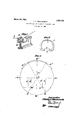
- FIG. 1 is a perspective view of a ring traveler in accordance with my invention applied to a spinning ring of standard type.
- Fig. 2 is an enlarged section through such traveler
- Fi 3 is an illustrative geometrical analysis of the gravity problem involved.
- circle as indicated in the diagram as a full circle having its geometrical centre at C, it will be seen that the circle would be in balance on its horizontal axis which I have indicated by the arrows BB as the axis of balance.
- the point C may therefore be considered for the moment as both the geometrical centre and as the axis of balance for a complete ring of metal of which it would be the centre.
- the mutilated circle has not, however, been restored to a state of balance or equilibrium on the two sides of the axis of balance.
- This state of balance or equilibrium consists of two factors. First, the factor of ponderability of the mutilated ring on each side of the axis of balance and second, the effective length of the leverage on each side.
- This leverage I have indicated as I, the same being that general distance from the axis of balance at which the weight of the ring on that side is affected. This, of course, is a resultant on each side of the ring, as the ring is not. absolutely identical on the two sides.
- the factors may be continuations of the slot disclosed in my original Patent, N 0. 1,415,069, or the lateral removal of material from the bow as indicated in my previous Patent No. 1,512,25 l, but as shown herein and as illustrating a wholly new type traveler, the removal of Weight from the traveler bow, with resultant lowering of the centre of gravity back to or below the geometrical centre of gravity, is accomplished by removing a definite slab of material transversely of the width of the traveler at the bow from edge to edge thereof as indicated at 4 in Figs. 1 and 2.
- the bow and horns may be of original uniform thickness, but after removal of the slab 4 from the how, the bow is of reduced thickness as compared with the horns.
- a ring traveler comprising a solid imperforate bow and terminal horns of uniform width throughout, said bow gradually de* creasing in thickness from the horns towards the center thereof so that the center of gravity of the traveler is lowered to a point corresponding approximately to the geometrical center of the traveler.
- a ring traveler having a solid imperforate bow and terminal horns which consists in forming the traveler of solid stock of uniform thickness and width throughout bow and horns, and in removing from the how a slab of material whereby the bow is of gradually decreasing thickness from the horns toward the center thereof so that the center of gravity of the traveler is lowered to a point corresponding approxi mately to the geometrical center of the traveler.
Landscapes
- Engineering & Computer Science (AREA)
- Mechanical Engineering (AREA)
- Textile Engineering (AREA)
- Spinning Or Twisting Of Yarns (AREA)
Description
March 20, 1928.
- 1,663,289 P. c. WENTWORTH RING TRAVELER AND METHOD OF PRODUCING SAME Filed May 11; 1927 fiuzenlvr Plu'ly'u flmulworlld Patented Mar. 20, 1928.
UNITED STATES PHILIP G. WENTWORTH, OF PROVIDENCE, QREODE ISLAND.
RING TRAVELER AND METHOD OF PRODUCINGSAME.
Application filed May 11,
As I understand the history of the ring traveler, there was at the time of its inception a theory that such a traveler would float upon the ring, being so supported by the yarn or thread that it had such a minimum physical contact with the ring that the friction was practically negligible. The pull on the yarn wassupposed to be regulated by the weight of the traveler, and for this reason there were introduced into the in dustry specifications'as to traveler Weights, which were most exacting, and these specifications have persisted through the years, to the great embarrassment of the manufacturer and at a very considerable cost in the production of travelers as specified.
It has, however, long been recognized that Whatever the original theory may have been, travelers do have such a very considerable frictional contact with the ring that there has been constant difficultyv both with the wearlog out of the traveler and even the wearing out of the ring itself. On this point there can be .no uncertainty at all.
It will therefore be seen that, aside from any other disturbing factors, faithfulness in production to exact specifications as to weighthave been probably more or less futile, because the element of friction-was so great that the resultant drag-of the traveler was only partly related to its weight. 7
The desideratum behind the original theory is, however, of even greater importance today than it was in the beginning of the industry fifty. years ago on account '0' the speeding up of production and other exacting causes in the development of the industry.
In my study of this problem I have conceived a way of realizing at least in a measure the original ideal of ring spinning and twisting. This conception, which may possibly be called a discovery, has to do with the effect of lowering the center ofgravity of the traveler without disturbing its other required functions, and thus providing travelers wi 11 a minimized frictional engagement with the ring which will approximate that theoretical ideal of the free floating traveler.
In this I find myself to some extent indebted to my own previous inventions as disclosed in my prior Letters Patent No. 1,415,069 and No. 1,461,059. In these two patents my preferred construction was a traveler in which a characteristic commerical form had a slotted bow originally intended these travelers,
1927. Serial no. 190,583.
as set forth in these patents for quite a dif- 'ferent purpose. In a rotostat observation of I detected running'postures which suggested to my mind a reduction of frictionon the horns of the travelers and with this the possibility of minimizing this frict on to a point where the original specified weights of travelers could be restored to their true reliability in functioning.
This matter of friction reduction, however, has a definite relation to traveler weights. It has alwaysbcen recognized that the heavier the traveler used (within the breaking limit of the yarn) the tighter the twist which could be given the yarn, but with the old-style travelers any increase in weight meant a corresponding increase in friction. By-minimizing the friction as I have done, however, I am 'able to use a correspondingly heavier traveler for the same number of yarn.
Briefly, the essence of my present conception consists in a lowering of the center of gravity in any style of travelers so that while produced in its specified weight andin substantially its usual design, the center of gravity would actually be lower than for the corresponding traveler heretofore, being in fact at or slightly below the geometrical center of the traveler. This results in a balancing of the traveler which enables it to float rather than ride on the ring. Such floating action was readily discernible by means of the rotostat machine which showed the traveler positioned vertically on the ring at all times and in all positions oftraverse of the ring rail stead of being tilted thereon as in the oldstyle traveler.
With this understanding of my invention, I will proceed at once to describe the production 0 a commercial traveler as an illustrative embodiment. I have shown such a traveler in the accompanying drawings, in
whichm v Fig. 1 is a perspective view of a ring traveler in accordance with my invention applied to a spinning ring of standard type. I
Fig. 2 is an enlarged section through such traveler, and
Fi 3 is an illustrative geometrical analysis of the gravity problem involved.
I haveindicated at R a portion of the traveler ring, at T the traveler and at Ythe yarn. Thetraveler is of the usual horseshoe form presenting a substantial semi-circular relative to the spindle intration.
body or bow portion 1 and inturned terminal horns 2 which are separated from each other by a gap or space 3 usually termed the flange.
In order to make my invention clear, I will first explain it from the purely theoretical side as it is one, partly at least, capable of geometrical demonstration and definitely involving laws of gravity and leverage. Referring therefore to the diagram in Fig. 3, I have shown in solid lines the characteristic outline of a traveler. It will be noted that the traveler, roughly speaking, shows in edge elevation an arc of something more than 180 from which the flanges turn inwardly generally parallel to the central horizontal'axis of the circle of which the bow is a segment.
Considering now that circle as indicated in the diagram as a full circle having its geometrical centre at C, it will be seen that the circle would be in balance on its horizontal axis which I have indicated by the arrows BB as the axis of balance. The point C may therefore be considered for the moment as both the geometrical centre and as the axis of balance for a complete ring of metal of which it would be the centre.
It is, of course, immediately apparent that the inturned horns of the traveler, if bent back into a continuation of the curvature of the bow, would tend to complete this theoretical circle. I have indicated the position of the horns which lying in the line of this true circle at III-I. This, of course, does not conform to actual manufacturing practice, but it is merely utilized for purposes of illus- The distance between the points HH maytherefore be considered as the gap which would be left if a segment of a true ring of metal were removed. The weight of this segment thus removed may be considered as W.
When such a ring with such a segment re moved is placed on an axis of balance BB as indicated, the ring would turn over due to the fact that the weight W was removed and the ring counterbalanced by the weight of the corresponding arc W on the opposite side of the circle. It iiiay therefore be considered in the first instance, that a portion of metal equal in weight to the arc 1V will be removed from the bow. This may be done in any desired manner.
lVith such an amount of metal W removed, the mutilated circle has not, however, been restored to a state of balance or equilibrium on the two sides of the axis of balance. This state of balance or equilibrium consists of two factors. First, the factor of ponderability of the mutilated ring on each side of the axis of balance and second, the effective length of the leverage on each side. This leverage I have indicated as I, the same being that general distance from the axis of balance at which the weight of the ring on that side is affected. This, of course, is a resultant on each side of the ring, as the ring is not. absolutely identical on the two sides.
I now come to the step of bending the mutilated circle to form the horns of the traveler. In this it may be considered that the ends H are moved to the position H This obviouslychanges the element L which is the leverage for the ponderability of the traveler on that side as indicated at L so that the balance between the two sides is lost and the new axis of balance would pass through a point C parallel to and above its first position. The point C may now be considered as the new gravity centre and which, as shown in Fig. 3, is positioned above the normal geometrical gravity centre Q.
As first explained, however, it is desirable to keep the centre of gravity as low as possible in the traveler. I have therefore removed from the bow of the traveler further weight as, for example, the portions W This again lowers the axis of balance, letting the gravity centre down from the point C to a point which we may assume is back to or even lower than the original centre C.
The factors may be continuations of the slot disclosed in my original Patent, N 0. 1,415,069, or the lateral removal of material from the bow as indicated in my previous Patent No. 1,512,25 l, but as shown herein and as illustrating a wholly new type traveler, the removal of Weight from the traveler bow, with resultant lowering of the centre of gravity back to or below the geometrical centre of gravity, is accomplished by removing a definite slab of material transversely of the width of the traveler at the bow from edge to edge thereof as indicated at 4 in Figs. 1 and 2. In such a traveler, the bow and horns may be of original uniform thickness, but after removal of the slab 4 from the how, the bow is of reduced thickness as compared with the horns.
I have shown the bow as solid and imperforate, but if desired, the milling out which removes the slab of material 4 from the traveler bow may be carried through the bow itself so as to obtain the benefit of the slotted traveler as regards the draft feature .disclosed in myprior Patent N 0. 1,415,069.
Various modifications in theconstruction and operation of my device may obviously be resorted to, all'without departing from the spirit of my invention, if within the limits of the appended claims.
What I therefore claim and desire to secure by Letters Patent is:
1. A ring traveler comprising a solid imperforate bow and terminal horns of uniform width throughout, said bow gradually de* creasing in thickness from the horns towards the center thereof so that the center of gravity of the traveler is lowered to a point corresponding approximately to the geometrical center of the traveler. t
2. The method of making a ring traveler having a solid imperforate bow and terminal horns, which consists in forming the traveler of solid stock of uniform thickness and width throughout bow and horns, and in removing from the how a slab of material whereby the bow is of gradually decreasing thickness from the horns toward the center thereof so that the center of gravity of the traveler is lowered to a point corresponding approxi mately to the geometrical center of the traveler.
3, The method of making a rin traveler having a solid imperforate bow an terminal horns, which consists in forming the traveler of solid stock of uniform thickness and width throughout bow and horns, and in transversely removing from the top face of the how a slab of material whereby the how is of gradually decreasing thickness from the horns toward the center thereof so that the center of gravity of the traveler is lowered to a point corresponding approximately to the geometrical center of the traveler.
In testimony whereof I afiix my signature.
PHILIP Ct VVENTWORTH.
Priority Applications (1)
| Application Number | Priority Date | Filing Date | Title |
|---|---|---|---|
| US190583A US1663289A (en) | 1927-05-11 | 1927-05-11 | Ring traveler and method of producing same |
Applications Claiming Priority (1)
| Application Number | Priority Date | Filing Date | Title |
|---|---|---|---|
| US190583A US1663289A (en) | 1927-05-11 | 1927-05-11 | Ring traveler and method of producing same |
Publications (1)
| Publication Number | Publication Date |
|---|---|
| US1663289A true US1663289A (en) | 1928-03-20 |
Family
ID=22701933
Family Applications (1)
| Application Number | Title | Priority Date | Filing Date |
|---|---|---|---|
| US190583A Expired - Lifetime US1663289A (en) | 1927-05-11 | 1927-05-11 | Ring traveler and method of producing same |
Country Status (1)
| Country | Link |
|---|---|
| US (1) | US1663289A (en) |
-
1927
- 1927-05-11 US US190583A patent/US1663289A/en not_active Expired - Lifetime
Similar Documents
| Publication | Publication Date | Title |
|---|---|---|
| US2010485A (en) | Antisnoring device | |
| US1663289A (en) | Ring traveler and method of producing same | |
| US1623532A (en) | Safety pin | |
| US1666714A (en) | Poration | |
| US1818845A (en) | Method of and machine for stranding special or figured wires | |
| US2118873A (en) | Traveler | |
| US1985608A (en) | Ring traveler | |
| US2120528A (en) | Spring assembly | |
| US3343361A (en) | Spindle attachment for spinning with reduced balloon | |
| US1298542A (en) | Paper-clip. | |
| US1914816A (en) | Paper clip | |
| US2002078A (en) | Textile apparatus | |
| US2591866A (en) | Condenser for long draft spinning | |
| US1512220A (en) | Flier | |
| US1450239A (en) | Hairpin | |
| US1676205A (en) | Method of constructing spinning-ring travelers | |
| US2086927A (en) | Transmission line support | |
| US1609871A (en) | Ophthalmic mounting | |
| US3157981A (en) | Traveler for use with spinning rings | |
| US1121378A (en) | Ring-traveler. | |
| US1773541A (en) | Thread holder for the threading guides of stocking machines | |
| US3132467A (en) | Ring spinner | |
| US1469530A (en) | Braiding die | |
| US2035973A (en) | Ring traveler | |
| US1464674A (en) | Island |