US1663288A - Machine for washing serving trays - Google Patents
Machine for washing serving trays Download PDFInfo
- Publication number
- US1663288A US1663288A US1663288DA US1663288A US 1663288 A US1663288 A US 1663288A US 1663288D A US1663288D A US 1663288DA US 1663288 A US1663288 A US 1663288A
- Authority
- US
- United States
- Prior art keywords
- trays
- receptacle
- feed screws
- stack
- rails
- Prior art date
- Legal status (The legal status is an assumption and is not a legal conclusion. Google has not performed a legal analysis and makes no representation as to the accuracy of the status listed.)
- Expired - Lifetime
Links
- 238000005406 washing Methods 0.000 title description 2
- XLYOFNOQVPJJNP-UHFFFAOYSA-N water Substances O XLYOFNOQVPJJNP-UHFFFAOYSA-N 0.000 description 6
- 230000005484 gravity Effects 0.000 description 1
Images

Classifications
-
- A—HUMAN NECESSITIES
- A47—FURNITURE; DOMESTIC ARTICLES OR APPLIANCES; COFFEE MILLS; SPICE MILLS; SUCTION CLEANERS IN GENERAL
- A47L—DOMESTIC WASHING OR CLEANING; SUCTION CLEANERS IN GENERAL
- A47L15/00—Washing or rinsing machines for crockery or tableware
- A47L15/24—Washing or rinsing machines for crockery or tableware with movement of the crockery baskets by conveyors
Definitions
- My present invention relates to machines for washing serving trays used in restaurants, cafeterias and the like and is of the type disclosed and claimed in a co-pending application jointly invented by myself and one W. A. Miller, filed June 13, 1921, under Serial Number 477,103, and has for its object to improve the same in the several particulars hereinafter noted.
- Fig. 1 is a perspective view of the invention
- Fig. 2 is a view principally in longitudinal central section
- Fig. 3 is a view principally in transverse vertical section
- Fig. 4 is a detail view with some parts sectioned on the line 4--4 of Fig. 2, on an enlarged scale;
- Fig. 5 is a fragmentary plan view of one of the feed screws and trays
- Fig. 6 is a perspective view of the free end of one of the switch rails.
- Fig. 7 is a detail view of one of the free ends of one of the switch rails and co-oper ating track rails, said track rail being shown in section.
- the numeral 8 indicates a water-contain ing drum or receptacle mounted on a skeleton frame 9 and having at its sides bearings 10.
- Said receptacle 8 has flat parallel sides and a curved bottom struck from a center at the axis of said bearings 10.
- the front wall of the receptacle 8 is on an incline and extends tangentially from the curved bottom, and the back wall'of said receptacle is on the same curve as said bottom and terminates substantially in a horizontal plane that extends through the axis of the bear ings 10.
- the front wall of the receptacle extends above the rear wall thereof, and the front upper edge portions of the sides of said receptacle extend horizontally rearward from the front wall thereof to a point directly above the axis of the bearings 10.
- the rear upper edge portions of the sides of the receptacle 8 are on the same curve as the rear wall of said receptacle.
- a drain pipe 11 Leading from the bottom of the receptacle 8 is a drain pipe 11 normally closed by a valve 12.
- An overflow pipe 13 leads from the receptacle 8, at the rear thereof, empties into the drain pipe 11 outward of the valve Serial No. 675,073.
- the receptacle 8 is a pair of guide rails 14: that extend from the upper edge of the front wall of said receptacle to a point above the rear wall thereof. These guide rails '14 rest on the front wall of the receptacle 8, and hence have the same inclination, and their rear end portions rest on the curved bottom and rear wall of said receptacle. Also within the receptacle 8 is a pair of curved guide rails 15,. the intermediate portions of which are concentric with the curved portions of the outer guide rails 14 and are radially spaced therefrom. The front ends of the guide rails 15 are inclined and extend tangentially from the curved portions of said rails. The inclined front portions of the guide rails 14 and 15 are in diverging relation, as shown in Fig. 2.
- the rear end portions of the guide rails 15 are tangentially extended to afford inclined extensions 16 that extend upward and forward over the receptacle 8 at an angle of substantially forty-five degrees and have at their extreme upper ends stop fingers 17.
- a pair of inclined switch rails 18 is intermediately pivoted at 19 to the rear upper ends of the guide rails 14, and their long or upper arms normally rest on the guide rail extensions 16 materially below the stop fingers 17.
- Curved rods 20, attached to the lower or short arm of the switch rails 18, work in guide holes the guide rails 14.
- Coiled springs 21, encircling the rods 20, are compressed between the guide rails 14 and switch rails 18 and yieldingly hold said switch rails on the guide rail extensions 16 with freedom for lifting movement therefrom.
- the upper ends of the switch rails 18 are undercut at 22 to receive the guide rail extensions 16, as best shown in Figs. 6 and 7, so that the upper surfaces of said switch rails are substantially flush with the respective surfaces of the guide rail extensions, 16.
- I For automatically feeding trays into the receptacle.
- I provide means for supporting a. stack of trays y and removing successive trays from the bottom of the stack and then release the same into the receptacle 8.
- This means may take various different forms and in the present commercial form of the machine I provide four feed screws 23 ar ranged in front and rear laterally spaced pairs.
- the threads 24: of the feed screws 23 are adapted to support a stack of trays y, and the upper ends of said threads are cut square and their upper surfaces beveled to afford wedge-acting points 25.
- These feed screws 23 are secured to upright shafts 26 journaled in bearings 2'7 secured by nutequipped bolts 28 to the frame 9 at the sides of the receptacle 8.
- the front pair of bearings 27 is made adjustable toward and from the rear pair of bearings 27 by extending the respective bolts 28 through slots 28 in said fran'le.
- the feed screws 23 have truncated conical upper end portions 29 above the threads 24 for directing the trays y onto said threads.
- Suitable means is provided for positively driving the feed screws 23, as will presently appear, and it is important to note that the feed screws 23 on one side of the machine are driven in an opposite direction from the feed screws on the other side thereof to neutralize the tendency of the trays 1 to move endwise on the threads 24 under the action of the rotation of said feed screws.
- I provide a reel head 30 having a short shaft 31 journaled in the bearing 10.
- a plurality of radial arm extensions 32 are secured to the reel head 30, work at one side of the guide rails 15, and have on their outer ends horizontal extensions 33 that extend transversly over said guide rails and radially inward therefrom.
- On each arm extension 32 is a pair of pins 34 that extend radially outward between the two guide rails 15 and are of such length as to engage a tray y on the guide rails 14, and push the same through the water 00 and above the the same onto the guide rail extensions 16.
- An electric motor 36 is mounted on a shelf 37 secured to the frame 9 under the front of the receptacle 8 and has on its armature shaft a grooved pulley 38 aligned with a relatively large grooved wheel 39 on the front end of a counter-shaft 40, and over which pulley 3'8 and wheel 39 runs a belt 11.
- the counter-shaft 40 is journaled in bearings 42 on the frame 9 and has on its rear end a worm 4-3 that meshes with a worm gear 4 1 on the shaft 31.
- Front and rear transverse shafts 45 and 46 are journaled, respectively, in the front and rear pairs of bearings 27 and have secured thereto bevelled pinions 17 which mesh with bevelled pinions 48 on the 'lower'ends of the shafts 26.
- a sprocket chain 49 runs over a relatively large sprocket wheel 50 on the shaft 31 and a relatively small sprocket wheel 51 on the rear shaft 46 and positively drives'the same.
- the front shaft 45 is driven from the rear shaft 4-6 by a sprocket chain 52 which runs over sprocket wheels 53 on the shafts 45 and 46.
- the driving of the shafts 45 and 46 and the arrangement and driving of the pinions 47 and 4-8 is such that the feed screws 23 on opposite sides of the machine are driven in reverse directions, as previously stated.
- the trays 3 are automatically removed from the bottom of a stack of trays supported on the threads 21, successively deposited into the receptacle 8, moved through the water therein onto the guide rail extensions 16 into draining positions, and from receptacle 8 properly position the stack of trays g as they are placed on the feed screws 23, and they also hold said stack against excessive endwise movement on said feed screws.
- the trays 3/ as they slide from the inclined shelf 35 will automatically form a stack and the height thereof will depend on the distance between said shelf and the table z, or if desired, the shelf 35 may be dispensed with and the trays 7 allowed to form a stack as they are delivered directly from the inclined switch rails 18.
- tray is herein used in a broad sense to cover plates or other objects that can be stacked.
- the above described invention has, in actual commercial usa e, proven highly eflicient for the purpose ha in view.
- a tray-supporting and releasing device comprising, in combination with a conveyor, a plurality of revoluble upright feed screws adapted to support a stack of tra s on their threads and successively remove t e trays from the bottom of the stack and then release the same to said conveyor, said feed screws having conical truncated upper end portions for directing the stack of trays onto their threads.
- a tray-supporting and releasing device having two pairs of revoluble upright feed screws rotated in opposite directions and adapted to support a stack of trays 011 their threads and successively remove the trays from the bot-tom of the stack and then release the same, said two pairs of feed screws being arranged to support the stack of trays therebetween.
Landscapes
- Washing And Drying Of Tableware (AREA)
Description
March 20, 1928. 1,663,288
' C. J. U LRICH MACHINE FOR WASHING SERVING TRAYS Filed Nov. 16. 1923 I5 Sheets-Sheet 1 March 20, 1928.
C. J. ULRICH MACHINE FOR WASHING SERVING TRAYS Filed Nov. 16, 1923 3 ih6ets-Sheet 2 March 20,1928.
c. J. ULRICH Filed Nov. 16. 1923 3 Sheets-Sheet 3 ,Z/Zr' 7 9 9 am [611K]. FJJy'cfi Z JIJAJW Patented Mar. 20, 1928.
UNITED STATES CARL J. ULRICH, OF MANKA'I'O, MINNESOTA.
MACHINE FOR WASHING SERVING TRAYS.
Application filed November 16, 1923.
My present invention relates to machines for washing serving trays used in restaurants, cafeterias and the like and is of the type disclosed and claimed in a co-pending application jointly invented by myself and one W. A. Miller, filed June 13, 1921, under Serial Number 477,103, and has for its object to improve the same in the several particulars hereinafter noted.
In the accompanying drawings, which illustrate the invention, like characters indicate like parts throughout the several views.
Referring to the drawings:
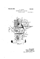
Fig. 1 is a perspective view of the invention;
Fig. 2 is a view principally in longitudinal central section;
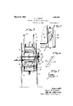
Fig. 3 is a view principally in transverse vertical section;
Fig. 4 is a detail view with some parts sectioned on the line 4--4 of Fig. 2, on an enlarged scale;
Fig. 5 is a fragmentary plan view of one of the feed screws and trays;
Fig. 6 is a perspective view of the free end of one of the switch rails; and
Fig. 7 is a detail view of one of the free ends of one of the switch rails and co-oper ating track rails, said track rail being shown in section.
The numeral 8 indicates a water-contain ing drum or receptacle mounted on a skeleton frame 9 and having at its sides bearings 10. Said receptacle 8 has flat parallel sides and a curved bottom struck from a center at the axis of said bearings 10. The front wall of the receptacle 8 is on an incline and extends tangentially from the curved bottom, and the back wall'of said receptacle is on the same curve as said bottom and terminates substantially in a horizontal plane that extends through the axis of the bear ings 10. The front wall of the receptacle extends above the rear wall thereof, and the front upper edge portions of the sides of said receptacle extend horizontally rearward from the front wall thereof to a point directly above the axis of the bearings 10. The rear upper edge portions of the sides of the receptacle 8 are on the same curve as the rear wall of said receptacle.
Leading from the bottom of the receptacle 8 is a drain pipe 11 normally closed by a valve 12. An overflow pipe 13 leads from the receptacle 8, at the rear thereof, empties into the drain pipe 11 outward of the valve Serial No. 675,073.
12, and determines the level of the water :0 in said receptacle.
lVithin the receptacle 8 is a pair of guide rails 14: that extend from the upper edge of the front wall of said receptacle to a point above the rear wall thereof. These guide rails '14 rest on the front wall of the receptacle 8, and hence have the same inclination, and their rear end portions rest on the curved bottom and rear wall of said receptacle. Also within the receptacle 8 is a pair of curved guide rails 15,. the intermediate portions of which are concentric with the curved portions of the outer guide rails 14 and are radially spaced therefrom. The front ends of the guide rails 15 are inclined and extend tangentially from the curved portions of said rails. The inclined front portions of the guide rails 14 and 15 are in diverging relation, as shown in Fig. 2.
The rear end portions of the guide rails 15 are tangentially extended to afford inclined extensions 16 that extend upward and forward over the receptacle 8 at an angle of substantially forty-five degrees and have at their extreme upper ends stop fingers 17.
A pair of inclined switch rails 18 is intermediately pivoted at 19 to the rear upper ends of the guide rails 14, and their long or upper arms normally rest on the guide rail extensions 16 materially below the stop fingers 17. Curved rods 20, attached to the lower or short arm of the switch rails 18, work in guide holes the guide rails 14. Coiled springs 21, encircling the rods 20, are compressed between the guide rails 14 and switch rails 18 and yieldingly hold said switch rails on the guide rail extensions 16 with freedom for lifting movement therefrom. The upper ends of the switch rails 18 are undercut at 22 to receive the guide rail extensions 16, as best shown in Figs. 6 and 7, so that the upper surfaces of said switch rails are substantially flush with the respective surfaces of the guide rail extensions, 16.
For automatically feeding trays into the receptacle. I provide means for supporting a. stack of trays y and removing successive trays from the bottom of the stack and then release the same into the receptacle 8. This means may take various different forms and in the present commercial form of the machine I provide four feed screws 23 ar ranged in front and rear laterally spaced pairs. The threads 24: of the feed screws 23 are adapted to support a stack of trays y, and the upper ends of said threads are cut square and their upper surfaces beveled to afford wedge-acting points 25. These feed screws 23 are secured to upright shafts 26 journaled in bearings 2'7 secured by nutequipped bolts 28 to the frame 9 at the sides of the receptacle 8. The front pair of bearings 27 is made adjustable toward and from the rear pair of bearings 27 by extending the respective bolts 28 through slots 28 in said fran'le. The purpose of this adjustment of the bearings 27 to position the feed screws 23 for trays that may vary slightly in width. The feed screws 23 have truncated conical upper end portions 29 above the threads 24 for directing the trays y onto said threads. Suitable means is provided for positively driving the feed screws 23, as will presently appear, and it is important to note that the feed screws 23 on one side of the machine are driven in an opposite direction from the feed screws on the other side thereof to neutralize the tendency of the trays 1 to move endwise on the threads 24 under the action of the rotation of said feed screws. During the rotation of the feed screws 23 the wedgeacting ends 25 of the threads 24 enter between the rolled rims of the two lowermost trays 11/ and separate the lowermost tray from the stack. The threads 24, acting on the separated tray 3 carry the same downward from. the stack and then release said tray into the receptacle 8. This released tray ;2 drops onto the inclined guide rails 14 and slides thereon into the water :12.
To convey the trays 3 through the water a: and above the same into draining positions on the guide rail extensions 16, I provide a reel head 30 having a short shaft 31 journaled in the bearing 10. A plurality of radial arm extensions 32, as shown three, are secured to the reel head 30, work at one side of the guide rails 15, and have on their outer ends horizontal extensions 33 that extend transversly over said guide rails and radially inward therefrom. On each arm extension 32 is a pair of pins 34 that extend radially outward between the two guide rails 15 and are of such length as to engage a tray y on the guide rails 14, and push the same through the water 00 and above the the same onto the guide rail extensions 16.
When a tray y supported on one pair of the pins 3a is lifted thereby out of the water 00, said tray is in a substantially vertical position, and under further lifting movement of said tray, the same tilts under the action, of gravity onto the guide rail extensions 16. As the tray 1 is pushed upward onto the guide rail extensions 16 by the respective pins 34. the upper rolled edge thereof engages the switch rails 18, lifts the same from the guide rail extensions 16 and allows the tray to pass thereunder and above the same. At the time the tray passes above the switch rails 18, the respective pins 34: move out of engagement therewith, and at the same time said switch rails are again closed under the action of the springs 21. As the trays y are released by the respective pins 3d, the same slide downward on the guide rail. extensions 16 onto the switch rails 13 and are conveyed thereby onto an inclined shelf 35 at the rear of the machine where they may be removed by an (merator who examines, dries and stacks the trays on the table a.
The following connections are provided for driving the reel head 30 and feed screws 23:
An electric motor 36 is mounted on a shelf 37 secured to the frame 9 under the front of the receptacle 8 and has on its armature shaft a grooved pulley 38 aligned with a relatively large grooved wheel 39 on the front end of a counter-shaft 40, and over which pulley 3'8 and wheel 39 runs a belt 11. The counter-shaft 40 is journaled in bearings 42 on the frame 9 and has on its rear end a worm 4-3 that meshes with a worm gear 4 1 on the shaft 31. For driving the feed screws 23 from the shaft 31, the following connections are provided: Front and rear transverse shafts 45 and 46 are journaled, respectively, in the front and rear pairs of bearings 27 and have secured thereto bevelled pinions 17 which mesh with bevelled pinions 48 on the 'lower'ends of the shafts 26. A sprocket chain 49 runs over a relatively large sprocket wheel 50 on the shaft 31 and a relatively small sprocket wheel 51 on the rear shaft 46 and positively drives'the same. The front shaft 45 is driven from the rear shaft 4-6 by a sprocket chain 52 which runs over sprocket wheels 53 on the shafts 45 and 46. The driving of the shafts 45 and 46 and the arrangement and driving of the pinions 47 and 4-8 is such that the feed screws 23 on opposite sides of the machine are driven in reverse directions, as previously stated. a
From the above description it is evident that the trays 3 are automatically removed from the bottom of a stack of trays supported on the threads 21, successively deposited into the receptacle 8, moved through the water therein onto the guide rail extensions 16 into draining positions, and from receptacle 8 properly position the stack of trays g as they are placed on the feed screws 23, and they also hold said stack against excessive endwise movement on said feed screws.
It may be here stated. that the trays 3/ as they slide from the inclined shelf 35 will automatically form a stack and the height thereof will depend on the distance between said shelf and the table z, or if desired, the shelf 35 may be dispensed with and the trays 7 allowed to form a stack as they are delivered directly from the inclined switch rails 18.
The term tray is herein used in a broad sense to cover plates or other objects that can be stacked.
The above described invention has, in actual commercial usa e, proven highly eflicient for the purpose ha in view.
What I claim is:
1. A tray-supporting and releasing device comprising, in combination with a conveyor, a plurality of revoluble upright feed screws adapted to support a stack of tra s on their threads and successively remove t e trays from the bottom of the stack and then release the same to said conveyor, said feed screws having conical truncated upper end portions for directing the stack of trays onto their threads.
2. A tray-supporting and releasing device having two pairs of revoluble upright feed screws rotated in opposite directions and adapted to support a stack of trays 011 their threads and successively remove the trays from the bot-tom of the stack and then release the same, said two pairs of feed screws being arranged to support the stack of trays therebetween.
3. The structure defined in claim 2 in which one pair of feed screws is adjustable toward and from the other pair of feed screws.
In testimony whereof I aflix my signature.
CARL J. ULRICH.
Publications (1)
| Publication Number | Publication Date |
|---|---|
| US1663288A true US1663288A (en) | 1928-03-20 |
Family
ID=3414733
Family Applications (1)
| Application Number | Title | Priority Date | Filing Date |
|---|---|---|---|
| US1663288D Expired - Lifetime US1663288A (en) | Machine for washing serving trays |
Country Status (1)
| Country | Link |
|---|---|
| US (1) | US1663288A (en) |
Cited By (10)
| Publication number | Priority date | Publication date | Assignee | Title |
|---|---|---|---|---|
| US2433736A (en) * | 1943-09-16 | 1947-12-30 | Dixie Cup Co | Dispensing apparatus |
| US2556740A (en) * | 1945-12-27 | 1951-06-12 | Blanche H Polsen | Cup dispenser |
| US2595013A (en) * | 1949-05-25 | 1952-04-29 | Colborne Mfg Company | Pie plate depositor |
| US2603363A (en) * | 1952-07-15 | Ware piling apparatus | ||
| US2692691A (en) * | 1950-04-15 | 1954-10-26 | Harriss | Nested article dispenser |
| US2993622A (en) * | 1954-12-23 | 1961-07-25 | Fmc Corp | Machine for packing eggs |
| US3001198A (en) * | 1956-04-10 | 1961-09-26 | Melpar Inc | Wafer feed and insertion |
| US3034683A (en) * | 1959-03-19 | 1962-05-15 | Reynolds Metals Co | Package dispenser |
| US3122230A (en) * | 1960-11-29 | 1964-02-25 | Donnelley & Sons Co | Transfer apparatus for books |
| US3980204A (en) * | 1974-12-05 | 1976-09-14 | Avant Industries, Inc. | Tray dispenser apparatus |
-
0
- US US1663288D patent/US1663288A/en not_active Expired - Lifetime
Cited By (10)
| Publication number | Priority date | Publication date | Assignee | Title |
|---|---|---|---|---|
| US2603363A (en) * | 1952-07-15 | Ware piling apparatus | ||
| US2433736A (en) * | 1943-09-16 | 1947-12-30 | Dixie Cup Co | Dispensing apparatus |
| US2556740A (en) * | 1945-12-27 | 1951-06-12 | Blanche H Polsen | Cup dispenser |
| US2595013A (en) * | 1949-05-25 | 1952-04-29 | Colborne Mfg Company | Pie plate depositor |
| US2692691A (en) * | 1950-04-15 | 1954-10-26 | Harriss | Nested article dispenser |
| US2993622A (en) * | 1954-12-23 | 1961-07-25 | Fmc Corp | Machine for packing eggs |
| US3001198A (en) * | 1956-04-10 | 1961-09-26 | Melpar Inc | Wafer feed and insertion |
| US3034683A (en) * | 1959-03-19 | 1962-05-15 | Reynolds Metals Co | Package dispenser |
| US3122230A (en) * | 1960-11-29 | 1964-02-25 | Donnelley & Sons Co | Transfer apparatus for books |
| US3980204A (en) * | 1974-12-05 | 1976-09-14 | Avant Industries, Inc. | Tray dispenser apparatus |
Similar Documents
| Publication | Publication Date | Title |
|---|---|---|
| US1663288A (en) | Machine for washing serving trays | |
| US2209340A (en) | Automatic feeding device | |
| US1794517A (en) | Machine for placing rings in envelopes | |
| US2699711A (en) | Carton erecting machine | |
| US2119596A (en) | Box dumping machine | |
| SE455901B (en) | DEVICE FOR EXHAUSTING A NUMBER OF MAIN SPHERICAL FORMS | |
| US3581750A (en) | Automatic scullery apparatus | |
| US2263811A (en) | Device for intermittently feeding rolling articles | |
| US1753036A (en) | Mail-sorting apparatus | |
| US3980204A (en) | Tray dispenser apparatus | |
| US1794198A (en) | Card-separating mechanism | |
| CN113318958A (en) | Automatic tableware sorting device | |
| US1850480A (en) | Feeding device for cans | |
| US1964152A (en) | Egg feeding machine | |
| US2279947A (en) | Grading machine | |
| US1954944A (en) | Can separating and feeding machine | |
| US1710199A (en) | Sizing machine | |
| CN215235663U (en) | A tableware automatic sorting device | |
| US3080797A (en) | Carton extractor and opener | |
| US1851958A (en) | Method and apparatus for sorting and distributing mail and the like | |
| US1545225A (en) | Tile-stacking machine | |
| US1902088A (en) | Laundry sorting machine | |
| US1663704A (en) | Egg candler | |
| US1200241A (en) | Assorting or grading machine. | |
| US2517341A (en) | Adjustable range egg-sorting machine |