US1663280A - Furnace-wall construction - Google Patents
Furnace-wall construction Download PDFInfo
- Publication number
- US1663280A US1663280A US190021A US19002127A US1663280A US 1663280 A US1663280 A US 1663280A US 190021 A US190021 A US 190021A US 19002127 A US19002127 A US 19002127A US 1663280 A US1663280 A US 1663280A
- Authority
- US
- United States
- Prior art keywords
- wall
- tile
- tiles
- section
- members
- Prior art date
- Legal status (The legal status is an assumption and is not a legal conclusion. Google has not performed a legal analysis and makes no representation as to the accuracy of the status listed.)
- Expired - Lifetime
Links
Images
Classifications
-
- F—MECHANICAL ENGINEERING; LIGHTING; HEATING; WEAPONS; BLASTING
- F27—FURNACES; KILNS; OVENS; RETORTS
- F27D—DETAILS OR ACCESSORIES OF FURNACES, KILNS, OVENS, OR RETORTS, IN SO FAR AS THEY ARE OF KINDS OCCURRING IN MORE THAN ONE KIND OF FURNACE
- F27D1/00—Casings; Linings; Walls; Roofs
- F27D1/0003—Linings or walls
- F27D1/004—Linings or walls comprising means for securing bricks
Definitions
- This invention relates to furnace Wall construction. and more especially to walls of considerable height, composed of an inner member of refractory material and an outer masonry member of any suitable character.
- the walls are relatively low, as deterioration of the refactory tile or firebrick composing the inner member, is increased at a. rate proportionate to the increase in the load imposed upon it.
- My olncct is to provide a wall construction composed of a plurality of independently supported sections at dillerent levels, to enable repairs to be made or arch openings to be formed in any section. without disturbing an underlying or overlying section.
- Another object is to provide a double wall containing: a row or rows of interlocle ing tile tying the wall members together and susceptible of conjoint upward movement or of differential upward movement in the event the inner wall member expands upwardly to a greater extent or degree than the outer wall member.
- a skeleton frame of metal for carrying the weight of the sections of: the wall above the bottom section, special types of: blocks or tile for suspension lrom the frame to serve as a bottom support for the immediately overlying section of the wall, and horizontal series of tiles or blocks, at one or more levels in each se tion of the wall,,to tie the inner and outer members of the wall together and at the same time accommodate differential expansion between the inner and outer members of the wall.
- Figure is a horizontal section of the wall, on the line II-II of Figure 1.
- Figure 3 is a horizontal section of the well taken on the line III-III of Figure 1.
- Figure at isv a detail perspective view of 1927. Serial No. 190,021.
- Figure 5 is a detail perspective view of a single suspension tile susceptible of use as a substitute for the sectional or double type of tile shown in Figure 1.
- FIG. 1 indicates a horizontal support or member of a suitable skeleton framework, not otherwise shown. as it may be of any suitable or preferred type that will sustain the horizontal support or a plurality thereof under a. predetermined load.
- the support shown in Figures 1 and 2 is in the form of two relatively rigid channel bars spaced a suit able distance apart to receive between them the upper hook or head end 2 of asuspension tile which may be of sectional construction as shown in Figures 1 and 2, or in a single piece as shown in Figure 5, it being understood that there will be a series of these tiles abutting, .sidewise together and extending for the full length of the Wall of which they "form apart. as shown by Figure 2.
- the suspension tiles serve to support opposite hanger tiles 3, the outer faces of said tiles defining, by preference, the Width of the wall of which they form a part.
- suspension and hanger tiles To interlock the suspension and hanger tiles so that the latter may form supports.
- the suspension tiles are formed at opposite sides with step portions 4, and the tread surfaces thereof are of substantially compound curve form in cross section or end View, so as to provide grooves 5 and tongues 6, the tongues hiring disposed outward of the grooves.
- the hanger tiles are formed at their upper ends with in verted step portions 7 of the same general contour as the step portions 4, and the step portions of the hanger tiles overlie the step portions of the suspension tiles. the tongues and grooves of the abutting tiles being mutually interlocked with each other.
- the tiles 3 depend to a lower plane than the suspension tile, for a purpose which hereinafter appears.
- a wall section of desired height is superimposed upon the tiles 3, and comprises an outer section 8 and an inner section 9, which are alike except that the former may be of ordinary masonry whereas the latter should be of refractory character, as constituting the innervvall of the furnace and therefore subject to greater heat
- the walls and 8 are alike except that the former may be of ordinary masonry whereas the latter should be of refractory character, as constituting the innervvall of the furnace and therefore subject to greater heat
- each section there may be several will sections of the character thus far described, arranged in superposed relation, and underlying each section are similar inner and outer wall members 8 and 9 spaced apart as at 10, the inner portions of the wall memhere being extended upward as at 12 bee tween the lower ends of the hanger tiles so as to provide an inverted tlshaped space 13 between said tile and the suspension tile and the said underlying wall members, which space is provided to absorb upward expansion of said underlying wall members, and to seal the wall against the entrance of air or escape of heat, the said joint is filled with suitable compressible material such as asbestos or other material 14, which will resist the action of heat.
- a horizontal series of tile 15 are employed to tie the two members of the wall against lateral or bulgingin ove ment, and these tile are preferably sorelated that those which form a part of the inner wall member are capable of movement upward independentl of those anchored more particularly in t e outer Wall member, this being desirable because the inner wall member is liable to greater upward expansion than the outer wall member.
- Each of such tiles partly underlies and forms a support for the juxtaposed overlapping tile, the overlapping portions of the tiles bearing a. tongue and groove relation as at 16 to lock them against separating movement in a horizontal plane by leaving each overlapping tile free to move upward from the underly' ing portion of the adjacent tile.
- the single piece suspension tile illustrated by Figure 5 may be employed as a support for the hanger tiles 3, it fitted edgewise between the supports or members .1, and then turned until its head or hook end overlaps the bottom flanged edges of said supports.
- the sectional type of suspension tile is preferred however, as easier handled, and by forming their adjacent faces at a suitable neeaaeo angle to provide a J-shaped space between them, it is possible to fit them in operative position by tilting them sidewise and then permit-ting them to swing to pendent position and abut at their lower edges.
- A. wall comprising superposed sections of masonry, ahorizontal metal supporting member above and spaced from one section and extending longitudinall of and through the overlying section, an tile suspended from the supporting member and underlying and supporting the section of the wall thrcugh which said supporting member exten s.
- a wall comprising superpcised sections or masonry, a horizontal metal supporting member above and spaced from one section and extending longitudinally of and through the overlying section, tile suspended from the supporting member and underlying and supporting the section of the wall through which said supporting member extends, and means cooperating with the metal supporting member in providing, for circulation of cool air in contact with the said member.
- a wall comprising superposed sections of masonry, a horizontal metal supporting member spaced above one of such masonry sections and extending longitudinally of and through the lower part of the overlying masonry section, tile suspended from the supporting member and underlying and supporting the section of the wall through which the supporting member extends, and spaced above the underlying wall section, and compressible sealing material interposed between said suspended tile and the underlying Wall section.
- a wall comprising a masonry section composed of an inner and an outer member spaced a art, a horizontal metal supporting mem er extending longitudinally of and through the wall at the lowerend thereof and providing a longitudinal air circulating channel between it and the masonry portion of the wall, and tile suspended from the supporting member and forming a bottom closure for said passage and underlying said member and the wall and forming a support for. the latter.
- a wall comprising superposed sections of masonry, a horizontal metal supportin member extending longitudinally of an through the wall below each section of masonry to be supported, tile suspended from the said member and provided with stepped outer faces, and tile having inverted stepped portions overlying and interlocked with the ste ped faces of the suspended tile and un der ying and supporting the section of the wall through which the supporting member extends.
- a wall comprising a pair of spaced horizontal supporting members of metal a tile suspended from said metal members and? tween said members, tiles at opposite sides of and interlocked with and suspended from the first-named tile and depending to a lower plane than the latter, spaced masonry walls at opposite sides of the supporting members and resting upon the last-named tiles, tiles resting upon and bridgin the space between said supporting mem ers and forming a part1t1on between said space and the space between the Wall members at opposite sides of said supporting members, a wall member composed of inner and outer members underlyingand spaced from the hanger tiles and rovided with upward extensions disposmf'between the said hanger tiles and spaced from the bottomof said suspended tile, and a compressible packing sealing the joint between the last-named wall members and the said tiles.
- a hanging furnace wall comprising a masonry column, a horizontal metal supporting member extending parallel to said column, and tile suspended from said sup; porting member and underlying and supporting said masonry column.
- masonry column a supporting membcr extending parallel to said column, and a tile suspended from said supporting member and underlying and supporting said masonry column.
- a hanging furnace wall comprising a pair of juxtaposed masonry columns, a supporting member extending between said masonry columns, and a tile suspended from av supporting member and underlying and supporting said masonry columns.
- a hanging furnace wall comprising a e
Landscapes
- Engineering & Computer Science (AREA)
- Mechanical Engineering (AREA)
- General Engineering & Computer Science (AREA)
- Finishing Walls (AREA)
Description
March 20, 1928. 1,663,280
G. P. REINTJES FURNACE WALL CONSTRUCTION Filed May 9, 192 7 INVENTOR. (Zea. E E6 g'zziieg UNITED STATES GEORGE P. REINTJES, OF KANSAS CITY, MISSOURI.
FURNACE-WALL oousrnuc'rrou.
Application filed May 9,
This invention relates to furnace Wall construction. and more especially to walls of considerable height, composed of an inner member of refractory material and an outer masonry member of any suitable character. In such walls repair or construction, especially of the inner members which are eX- posed to direct action of heatis necessary more frequently than it the walls are relatively low, as deterioration of the refactory tile or lirebrick composing the inner member, is increased at a. rate proportionate to the increase in the load imposed upon it.
My olncct is to provide a wall construction composed of a plurality of independently supported sections at dillerent levels, to enable repairs to be made or arch openings to be formed in any section. without disturbing an underlying or overlying section. Another object is to provide a double wall containing: a row or rows of interlocle ing tile tying the wall members together and susceptible of conjoint upward movement or of differential upward movement in the event the inner wall member expands upwardly to a greater extent or degree than the outer wall member.
Accordinoly I employ a skeleton frame of metal for carrying the weight of the sections of: the wall above the bottom section, special types of: blocks or tile for suspension lrom the frame to serve as a bottom support for the immediately overlying section of the wall, and horizontal series of tiles or blocks, at one or more levels in each se tion of the wall,,to tie the inner and outer members of the wall together and at the same time accommodate differential expansion between the inner and outer members of the wall.
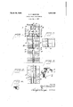
With the objects n.ent-ioned in View, the invention consists in certain novel and use-- tul features of construction and combinations of parts as hereinafter described and claimed; and in order that it maybe fully understood, reference is to. be had to the. accompanying drawing, in which Figure l is a vertical section of a wall embodying the invention, taken on the line II of Figure 2.
Figure is a horizontal section of the wall, on the line II-II of Figure 1.
Figure 3 is a horizontal section of the well taken on the line III-III of Figure 1.
Figure at isv a detail perspective view of 1927. Serial No. 190,021.
one of the series of tie blocks for the inner and outer members of the wall.
Figure 5 is a detail perspective view of a single suspension tile susceptible of use as a substitute for the sectional or double type of tile shown in Figure 1. l
Referring now to the drawing in detail 1 indicates a horizontal support or member of a suitable skeleton framework, not otherwise shown. as it may be of any suitable or preferred type that will sustain the horizontal support or a plurality thereof under a. predetermined load. The support shown in Figures 1 and 2, is in the form of two relatively rigid channel bars spaced a suit able distance apart to receive between them the upper hook or head end 2 of asuspension tile which may be of sectional construction as shown in Figures 1 and 2, or in a single piece as shown in Figure 5, it being understood that there will be a series of these tiles abutting, .sidewise together and extending for the full length of the Wall of which they "form apart. as shown by Figure 2. The suspension tiles serve to support opposite hanger tiles 3, the outer faces of said tiles defining, by preference, the Width of the wall of which they form a part.
To interlock the suspension and hanger tiles so that the latter may form supports.
for a superposed section of the Wall of predetermined height, the suspension tiles are formed at opposite sides with step portions 4, and the tread surfaces thereof are of substantially compound curve form in cross section or end View, so as to provide grooves 5 and tongues 6, the tongues hiring disposed outward of the grooves. The hanger tiles are formed at their upper ends with in verted step portions 7 of the same general contour as the step portions 4, and the step portions of the hanger tiles overlie the step portions of the suspension tiles. the tongues and grooves of the abutting tiles being mutually interlocked with each other. In the preferred construction the tiles 3 depend to a lower plane than the suspension tile, for a purpose which hereinafter appears.
A wall section of desired height is superimposed upon the tiles 3, and comprises an outer section 8 and an inner section 9, which are alike except that the former may be of ordinary masonry whereas the latter should be of refractory character, as constituting the innervvall of the furnace and therefore subject to greater heat The walls and 8,
lid
till
from a point slightly above the support or supports, are spaced apart by preference to provide an air space 10, and in order that the space within or between the support or supports may constitute a cooling passage, tile 11 are arranged to bridge the support and therefore form a top wall for said space.
in a tall furnace there may be several will sections of the character thus far described, arranged in superposed relation, and underlying each section are similar inner and outer wall members 8 and 9 spaced apart as at 10, the inner portions of the wall memhere being extended upward as at 12 bee tween the lower ends of the hanger tiles so as to provide an inverted tlshaped space 13 between said tile and the suspension tile and the said underlying wall members, which space is provided to absorb upward expansion of said underlying wall members, and to seal the wall against the entrance of air or escape of heat, the said joint is filled with suitable compressible material such as asbestos or other material 14, which will resist the action of heat.
In each section of the wall composed of members 8 ahd 9, a horizontal series of tile 15 are employed to tie the two members of the wall against lateral or bulgingin ove ment, and these tile are preferably sorelated that those which form a part of the inner wall member are capable of movement upward independentl of those anchored more particularly in t e outer Wall member, this being desirable because the inner wall member is liable to greater upward expansion than the outer wall member. Each of such tiles partly underlies and forms a support for the juxtaposed overlapping tile, the overlapping portions of the tiles bearing a. tongue and groove relation as at 16 to lock them against separating movement in a horizontal plane by leaving each overlapping tile free to move upward from the underly' ing portion of the adjacent tile. By this arrangement it will be apparent that the wall members are tied together but that the tiles forming more directly a part of the inner wall member permit of upward expansion of said member independent of the outer member, and yet maintain the tie between the two members, it being of course understood that the maximum upward expansion of the inner member must be less than the depth of the interlocking tongues and grooves between said tiles.
The single piece suspension tile illustrated by Figure 5, may be employed as a support for the hanger tiles 3, it fitted edgewise between the supports or members .1, and then turned until its head or hook end overlaps the bottom flanged edges of said supports. The sectional type of suspension tile is preferred however, as easier handled, and by forming their adjacent faces at a suitable neeaaeo angle to provide a J-shaped space between them, it is possible to fit them in operative position by tilting them sidewise and then permit-ting them to swing to pendent position and abut at their lower edges.
From the toregoin it will be apparent that I have provided a wall construction which embodies the features set forth as desirable in the statement of the objects of the invention, and which is susceptible of modification within the principle of construction involved and the spirit and scope of the appended claims. I
l'claim:
1. A. wall comprising superposed sections of masonry, ahorizontal metal supporting member above and spaced from one section and extending longitudinall of and through the overlying section, an tile suspended from the supporting member and underlying and supporting the section of the wall thrcugh which said supporting member exten s.
2. A wall comprising superpcised sections or masonry, a horizontal metal supporting member above and spaced from one section and extending longitudinally of and through the overlying section, tile suspended from the supporting member and underlying and supporting the section of the wall through which said supporting member extends, and means cooperating with the metal supporting member in providing, for circulation of cool air in contact with the said member.
3. A wall comprising superposed sections of masonry, a horizontal metal supporting member spaced above one of such masonry sections and extending longitudinally of and through the lower part of the overlying masonry section, tile suspended from the supporting member and underlying and supporting the section of the wall through which the supporting member extends, and spaced above the underlying wall section, and compressible sealing material interposed between said suspended tile and the underlying Wall section.
4. A wall comprising a masonry section composed of an inner and an outer member spaced a art, a horizontal metal supporting mem er extending longitudinally of and through the wall at the lowerend thereof and providing a longitudinal air circulating channel between it and the masonry portion of the wall, and tile suspended from the supporting member and forming a bottom closure for said passage and underlying said member and the wall and forming a support for. the latter.
5. A wall comprising superposed sections of masonry, a horizontal metal supportin member extending longitudinally of an through the wall below each section of masonry to be supported, tile suspended from the said member and provided with stepped outer faces, and tile having inverted stepped portions overlying and interlocked with the ste ped faces of the suspended tile and un der ying and supporting the section of the wall through which the supporting member extends.
6. A wall comprising a pair of spaced horizontal supporting members of metal a tile suspended from said metal members and? tween said members, tiles at opposite sides of and interlocked with and suspended from the first-named tile and depending to a lower plane than the latter, spaced masonry walls at opposite sides of the supporting members and resting upon the last-named tiles, tiles resting upon and bridgin the space between said supporting mem ers and forming a part1t1on between said space and the space between the Wall members at opposite sides of said supporting members, a wall member composed of inner and outer members underlyingand spaced from the hanger tiles and rovided with upward extensions disposmf'between the said hanger tiles and spaced from the bottomof said suspended tile, and a compressible packing sealing the joint between the last-named wall members and the said tiles. 1 v
7. A hanging furnace wall comprising a masonry column, a horizontal metal supporting member extending parallel to said column, and tile suspended from said sup; porting member and underlying and supporting said masonry column.
masonry column, a supporting membcr extending parallel to said column, and a tile suspended from said supporting member and underlying and supporting said masonry column.
9. A hanging furnace wall comprising a pair of juxtaposed masonry columns, a supporting member extending between said masonry columns, and a tile suspended from av supporting member and underlying and supporting said masonry columns.
In testimony whereof I afiix my signature.
GEORGE P. REINTJES.
8. A hanging furnace wall comprising a e
Priority Applications (1)
| Application Number | Priority Date | Filing Date | Title |
|---|---|---|---|
| US190021A US1663280A (en) | 1927-05-09 | 1927-05-09 | Furnace-wall construction |
Applications Claiming Priority (1)
| Application Number | Priority Date | Filing Date | Title |
|---|---|---|---|
| US190021A US1663280A (en) | 1927-05-09 | 1927-05-09 | Furnace-wall construction |
Publications (1)
| Publication Number | Publication Date |
|---|---|
| US1663280A true US1663280A (en) | 1928-03-20 |
Family
ID=22699732
Family Applications (1)
| Application Number | Title | Priority Date | Filing Date |
|---|---|---|---|
| US190021A Expired - Lifetime US1663280A (en) | 1927-05-09 | 1927-05-09 | Furnace-wall construction |
Country Status (1)
| Country | Link |
|---|---|
| US (1) | US1663280A (en) |
Cited By (1)
| Publication number | Priority date | Publication date | Assignee | Title |
|---|---|---|---|---|
| RU2559257C1 (en) * | 2014-06-16 | 2015-08-10 | Константин Евгеньевич Бессонов | Method of installation of cladding panel of external lining of furnace |
-
1927
- 1927-05-09 US US190021A patent/US1663280A/en not_active Expired - Lifetime
Cited By (1)
| Publication number | Priority date | Publication date | Assignee | Title |
|---|---|---|---|---|
| RU2559257C1 (en) * | 2014-06-16 | 2015-08-10 | Константин Евгеньевич Бессонов | Method of installation of cladding panel of external lining of furnace |
Similar Documents
| Publication | Publication Date | Title |
|---|---|---|
| US2150459A (en) | Insulating refractory wall | |
| US1663280A (en) | Furnace-wall construction | |
| US1657453A (en) | Furnace wall | |
| US2143280A (en) | Suspended furnace wall | |
| US1806113A (en) | Furnace wall | |
| US2156008A (en) | Continuous furnace | |
| US2127842A (en) | Furnace construction | |
| US2359619A (en) | Furnace or boiler arch | |
| US2081417A (en) | Furnace wall construction | |
| US2294788A (en) | Furnace wall construction | |
| US1798331A (en) | Fire wall | |
| US2742002A (en) | Sealing shoe for furnaces | |
| US1927909A (en) | Furnace wall construction | |
| US1581817A (en) | Furnace-wall construction | |
| US1961510A (en) | Furnace and regenerator construction therefor | |
| US1588118A (en) | Baffle-wall support | |
| US2107524A (en) | Fire wall construction | |
| US2818035A (en) | Unit expansion furnace walls | |
| US2299874A (en) | Furnace wall construction | |
| US1843384A (en) | Furnace wall | |
| US1326753A (en) | Furnace-arch for boilers | |
| US2294108A (en) | Furnace arch | |
| US2665895A (en) | Soaking pit curb wall with fixed elevation | |
| US1529242A (en) | Steam-boiler furnace | |
| US1747824A (en) | Furnace-wall construction |