US1663270A - Draft equalizer - Google Patents
Draft equalizer Download PDFInfo
- Publication number
- US1663270A US1663270A US114569A US11456926A US1663270A US 1663270 A US1663270 A US 1663270A US 114569 A US114569 A US 114569A US 11456926 A US11456926 A US 11456926A US 1663270 A US1663270 A US 1663270A
- Authority
- US
- United States
- Prior art keywords
- supplemental
- chain
- bolt
- evener
- draft
- Prior art date
- Legal status (The legal status is an assumption and is not a legal conclusion. Google has not performed a legal analysis and makes no representation as to the accuracy of the status listed.)
- Expired - Lifetime
Links
- 230000000153 supplemental effect Effects 0.000 description 59
- 238000010276 construction Methods 0.000 description 2
- 241001255830 Thema Species 0.000 description 1
- 230000004048 modification Effects 0.000 description 1
- 238000012986 modification Methods 0.000 description 1
Images

Classifications
-
- B—PERFORMING OPERATIONS; TRANSPORTING
- B62—LAND VEHICLES FOR TRAVELLING OTHERWISE THAN ON RAILS
- B62C—VEHICLES DRAWN BY ANIMALS
- B62C5/00—Draught assemblies
- B62C5/04—Swingletrees; Mountings thereof; Draught equalisers for a span of draught animals; Mountings for traces
Definitions
- This invention relates to draft equalizers and has relation more particularly to a device of this kind of a four horse equalizer, and it is primarily an object of the invention to provide a deviceof this character whereby the draft is equal at all times irrespective of the'positions of'the equalizing members.
- v y The invention consists in the details of construction and in the combination and arrangen'ient of the several parts of my improved draft equalizer whereby certain important advantages are attained and the do vice rendered simpler, less expensive and otherwise more convenient and advantageous for use, as will be hereinafter more fully set forth.
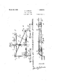
- FIG. 1 is a view in t p plan illustrating a draft equalizer constructed in accordance with an embodiment of my invention
- Figure 2 is a sectional view taken substantially on the line 2-2 of Figure 1;
- Figure 3 is an enlarged fragmentary 'view in top plan with portions'broken away of the main draft or evener member
- Figure 4 is an enlarged sectional view taken substantially on the line 4- 1 of Figure 1;
- Figure 5 is a the inner end portion of the supplemental evener or draft member;
- Figure 6 is a fragmentary view. in top plan with a portion broken away illustrating in detail the operative connection of the flexible member or chain withthe'inner end portion of the supplemental draft or evener member and with a doubletree. s
- M denotes thema n equalizing or draft member and which, asherem d1sclosed,fcomprises an elongated metallic plate 1 of requisite thlckness and which is returned ends of said plates; spaced substantiallytwenty-four inches from view in front elevationiof.
- the beam 2 is held in applied position by the bolts at and 5 disposed through the plates at and the beam 2.
- the bolt 5 is positioned at substantially the longitudinal center of the member M while the bolt 4 is adjacent to the free ends ofthe plates at and substantially twenty-four inches from the bolt 5.
- the opening or slot 3 is intersected by a bolt 6 disposed through the plates a and in relatively close proximity to the connected This bolt 6 is also the bolt 5.
- a pulley or roller 7 Rotatably mounted upon the bolt 6 and positioned within the opening or slot 3 is a pulley or roller 7 with which is engaged the chain 8 which will hereinafter be more to the clevis C 'being'of this type as any other form can be employedas the requirements of-practice may necessitate.
- the upper and lower faces of the applied beam 2 are provided with the substantially semi-circular recesses 10 which, in connection with the overlying portions of the plates a, provide pockets in which are adapted to be received the inner end portions ofthe forwardly directed arms 11.
- the outer end portions of the arms 11 overlie the upper and lower faces of the supplemental draft or equalizing member S and are pivotally connected thereto by the bolt 12.
- the bolt 12 is spaced, in a direction lengthwise of the arms 11, from the bolt 5 a distance of substantially twenty-four inches.
- These arms 11 provide means for maintaining the supplemental member S in proper assembly or relation with respect to the member M and its pivotal connection with said arms 11 by the bolt 12 permits the member S also to have swinging movement about the bolt 12 with relation to the arms 11.
- the right end portion of the member S has bolted, as at 1 1, to the upper and lower faces thereof the side arms 15 of a substantially U-shaped bracket B the intermediate portion of which being outwardly disposed.
- the extremity of the member S between the side arms 15 preferably are gradually reduced in width as at 16 ( Figure 1), said reduced portion 16 having a slot or kerf 17 intersected by a removable bolt 18.
- This removable bolt 18 is directed through the portion 16 of the member S and the adjacent portions of the arms 15 of the bracket B.
- the bolt 18 is spaced from the bolt 12 a distance of substantially twenty-four inches.
- the bolt 18 is selectively disposed through a link of the chain 8 hereinbefore referred to whereby an end portion of such chain 8 is effectively and conveniently anchored to the right end of the member S.
- This chain 8 is also disposed around a pulley 19 carried by a doubletree 20 and positoned rearwardly thereof.
- the pulley 19, as herein disclosed, is supportedby the rearwardly directed straps 21 carried by the doubletree 20.
- the opposite or left end portion of the member S has disposed therethrough at a point spaced substantially twenty-eight inches from the bolt 12 the bolt 22 extending above and below the member S and provides a pivotal mounting for the forwardly directed straps 23 each of which in turn being pivotally connected, as at 24, withzthe central portion of a doubletree 25.
- the bolt 22 also provides a mounting for the rear wardly disposedelongated clevis 26 to which is attached the second extremity of the chain 8 hereinbefore referred to.
- the member S has directed thcrethough the bolt 27 extending above and below the member S and to which extended portions are pivotally engaged the forward end portions of the rigid pulling straps 28.
- the opposite or rear end portions of these straps are freely or pivotally engaged with the upper and lower end portions of the bolt 4 hereinbefore referred to.
- the bolt 18 permits the chain 8 to be adjustably connected or attached to the right end of the member S in accordance with the extent it is desired to have the doubletrce 20 or more particularly the pulley 19 positioned in advance of the member S.
- my equalizer device as herein disclosed is of a four horse type and the assembly and arrangement of the parts as hereinbefore set forth are such that the pull of the teams hitched to the doubletrees 20 and 25 will assure equal draft in all positions of the members M and S.
- the chain 8 is disposed between the side arms of the bracket B in order that the bracket may afford an effective support for the doubletree 20.
- the bracket B is of such construction that when it is in applied position it provides an elongated opening or slot in which the chain 8 can work.
- a-doubletree connected with the outer extremity of the longer portion of the supplemental member, a chain secured to the end portion of said longer side of the supplemental member, the end portion of the main evener member remote from the connection of the chain with the supplemental member carrying a pulley, said chain extending around such pulley and extending forwardly therefrom, means for connecting the outer extremity of the shorter portion of the supplemental member to the chain, a second'doubletree having a pulley around which the chain directed, and straps connecting the longer portion of the supplemental member and the main evener member.
- a draft equalizer comprising a main evener member, a supplemental evener member in advance thereof, arms pivotally connected with the central portion of the main member and to the supplemental member at. a point to one side of its longitudinal center whereby the portion of the supplemental member at one side of the-arms is longer than at the other side, a doubletree'connected with the outer extremity of the longer portion of the supplemental member, a chain secured to the end portion of said longer side of the supplementalmember, the end portion of the main evener member remote from the connection of the chain with the supplemental member carrying a pulley, said chain extending around such pulley and extending forwardly therefrom, means for connecting the outer extremity of the shorter portion of the supplemental member to the chain, a seconddoubletree having a pulley around which the chain is directed, and straps connecting the longer portion of the supplemental member and the main evener member, the connection between the chain and the supplemental member comprising a bolt passing through said supplemental member and through a link of the chain, said
- a draft equalizer comprising a main evener member, a supplemental evener member in advance thereof, arms pivotally connected with the central portion of the main member and to the supplemental member at a point to one side of its longitudinal center whereby the portion of the supplemental member at one side of the arms is longer than at the other side, a doubletree connected with the outer extremity of the longer portion of the supplemental member, a'chain secured to the end portion of said longer side of the supplemental member, the end portion of the main evener member remote from the connection of the chain with the supplemental member carrying a pulley, said chain extending around such pulley and extending forwardly therefrom, means for connecting the outer extremity of the shorter portion of the supplemental member to the chain, a seconddoubletree having a pulley around which the chain is directed, and straps connecting the longer portion of the supplemental member and the main evener'memher, the central portion of the main evener whereby the portion of the supplemental member at one side of the arms is longer than at the other side,
- a draft equalizer comprising a main evener member, a supplemental evener mem her, arms connecting the centralportion of the main member with the supplemental member, the portion of the supplemental member at one side ofthe center of the draft being longer than on the opposite side.
- rigid bars connecting one end portion of the main member and the longer side of the supplemental member, a pulley carried by the opposite end portion of the main member, a flexible member secured to the longer side of the supplemental memher and passing around the pulley and secured to the shorter side of the supplemental member, a doubletree connected to the longer side of the supplemental member, and a second doubletree carrying a pulley with which the flexible member is engaged.
- a draft equalizer comprising a main evener, a supplemental evener member disposed in advance of the main evener, a connector from the main evener to the supplemental evener having: connection with the latter at a point intermediate its length, draft means connected to one end of the supplemental member, separate draft means for the other end of the supplemental memher, and an equalizing connection connected to the end of the supplemental member to which the first-mentioned draft means is attached and extending between the main and supplemental evener members, said sep arate draft means being connected to the equalizing connection at the other end of the supplemental member.
- a draft equalizer comprising a main evener, a supplemental evener member disposed in advance of the main evener, a connector between the main evener and the supplemental member and having connection with the latter at a point at one side of its longitudinal center whereby to provide a relatively long arm and a relatively short arm, draft means connected to the relatively long arm, a flexible equalizer eonnection having connection with the rela tively long arm and with the main evener at the end remote from the relatively long arm, said flexible equalizing member being also connected with the short arm of the supplemental member, and draft means hav' ing connection with the flexible member whereby draft stress is applied to the supplemental member from opposite sides of the same.
- a draft equalizer comprising a main evener, a supplemental evener member disposed in advance of the main evener, a connector bar between said evener members and having connection with the supplemental member at a point at one side of its longitudinal center whereby to provide relatively long and short arms, a second connection between one end of the main evener and the long arm of the supplemental member, a flexible equalizing member having fixed connection with the relatively long arm and extending from the latter to the remote end of the main evener with relation to said long arm and then forwardly to the relatively short arm of the supplemental member.
- draft means having connection with the flexible equalizer member at the end of the relatively short arm, and other draft means connected with the relatively long arm of the supplemental member.
Landscapes
- Engineering & Computer Science (AREA)
- Transportation (AREA)
- Mechanical Engineering (AREA)
- Agricultural Machines (AREA)
Description
March 20, '1928.
G. JOHNSQN DRAFT EQUALIZER Filed June 8. 1926 2 Sheets-Shae; l
March 20, 1928. 1,663,270
. G. JOHNSON DRA FT EQUALIZER Filed June 8. 1926 2 Sheets-Sheet 2 mills Patented Mar. 20, 1928.
UNITED STATES GUST JOHNSON, OF ORRIN, NORTH DAKOTA.
DRAFT EQUALIZER.
Application filed June 8,
This invention relates to draft equalizers and has relation more particularly to a device of this kind of a four horse equalizer, and it is primarily an object of the invention to provide a deviceof this character whereby the draft is equal at all times irrespective of the'positions of'the equalizing members.
It is also an object of the invention to provide a device of this kind adapted for use in connection with a plow or other agricultural implement or machine whereby equal draft is assured, thus eliminating side draft and particularly when used in connection with a plow. v y The invention consists in the details of construction and in the combination and arrangen'ient of the several parts of my improved draft equalizer whereby certain important advantages are attained and the do vice rendered simpler, less expensive and otherwise more convenient and advantageous for use, as will be hereinafter more fully set forth.
The novel features of my invention will hereinafter be definitely claimed.
In order that my invention may be the better understood, I will now proceed to describe the same with reference to the accompanying drawings, wherein i I Figure 1 is a view in t p plan illustrating a draft equalizer constructed in accordance with an embodiment of my invention;
Figure 2 is a sectional view taken substantially on the line 2-2 of Figure 1;
Figure 3 is an enlarged fragmentary 'view in top plan with portions'broken away of the main draft or evener member;
Figure 4 is an enlarged sectional view taken substantially on the line 4- 1 of Figure 1; Figure 5 is a the inner end portion of the supplemental evener or draft member; Figure 6 is a fragmentary view. in top plan with a portion broken away illustrating in detail the operative connection of the flexible member or chain withthe'inner end portion of the supplemental draft or evener member and with a doubletree. s
As disclosed in the accompanying drawa r I g ings, M denotes thema n equalizing or draft member and which, asherem d1sclosed,fcomprises an elongated metallic plate 1 of requisite thlckness and which is returned ends of said plates; spaced substantiallytwenty-four inches from view in front elevationiof.
1926. Serial at. 114,569.
upon itself, as particularly illustrated in Figure 1, to provide the upper and lower plates a between which is snugly engaged an elongated beam 2. This beam 2 extendsfrom a point immediately adjacent to the free ends of the plates a'to a predetermined point inwardly of the connected extremities of the plates a whereby an elongated openingr or slot 3 is provided in what may be termed the right end portion of the member M. The
beam 2 is held in applied position by the bolts at and 5 disposed through the plates at and the beam 2. The bolt 5 is positioned at substantially the longitudinal center of the member M while the bolt 4 is adjacent to the free ends ofthe plates at and substantially twenty-four inches from the bolt 5. The opening or slot 3 is intersected by a bolt 6 disposed through the plates a and in relatively close proximity to the connected This bolt 6 is also the bolt 5. Rotatably mounted upon the bolt 6 and positioned within the opening or slot 3 is a pulley or roller 7 with which is engaged the chain 8 which will hereinafter be more to the clevis C 'being'of this type as any other form can be employedas the requirements of-practice may necessitate.
At a point midway between the bolts 4 and6 the upper and lower faces of the applied beam 2 are provided with the substantially semi-circular recesses 10 which, in connection with the overlying portions of the plates a, provide pockets in which are adapted to be received the inner end portions ofthe forwardly directed arms 11.
The portions of "the arms 11 within the pockets or recesses 10 are pivotally or freely engaged with the bolt '5 hereinbefore referred to whereby'the member M and the arms 11 may readily have relative swinging move mentabout the bolt 5. s
The outer end portions of the arms 11 overlie the upper and lower faces of the supplemental draft or equalizing member S and are pivotally connected thereto by the bolt 12. In this assembly the bolt 12 is spaced, in a direction lengthwise of the arms 11, from the bolt 5 a distance of substantially twenty-four inches. These arms 11 provide means for maintaining the supplemental member S in proper assembly or relation with respect to the member M and its pivotal connection with said arms 11 by the bolt 12 permits the member S also to have swinging movement about the bolt 12 with relation to the arms 11.
The right end portion of the member S has bolted, as at 1 1, to the upper and lower faces thereof the side arms 15 of a substantially U-shaped bracket B the intermediate portion of which being outwardly disposed. The extremity of the member S between the side arms 15 preferably are gradually reduced in width as at 16 (Figure 1), said reduced portion 16 having a slot or kerf 17 intersected by a removable bolt 18. This removable bolt 18 is directed through the portion 16 of the member S and the adjacent portions of the arms 15 of the bracket B.
The bolt 18 is spaced from the bolt 12 a distance of substantially twenty-four inches. The bolt 18 is selectively disposed through a link of the chain 8 hereinbefore referred to whereby an end portion of such chain 8 is effectively and conveniently anchored to the right end of the member S. This chain 8 is also disposed around a pulley 19 carried by a doubletree 20 and positoned rearwardly thereof. The pulley 19, as herein disclosed, is supportedby the rearwardly directed straps 21 carried by the doubletree 20.
The opposite or left end portion of the member S has disposed therethrough at a point spaced substantially twenty-eight inches from the bolt 12 the bolt 22 extending above and below the member S and provides a pivotal mounting for the forwardly directed straps 23 each of which in turn being pivotally connected, as at 24, withzthe central portion of a doubletree 25. The bolt 22 also provides a mounting for the rear wardly disposedelongated clevis 26 to which is attached the second extremity of the chain 8 hereinbefore referred to.
Whilel herein show the chain 8 connected to the outer end of the long portion of the member S it is to be understood that the chain 8 can be connected to said member S at other points on the long portion with connection of the bar 28 to the long arm is shifted accordingly. If the chain 8 is connected to the bolt 27, the distance between said bolt and the bolt 12 should be one-quarter of the length of the main evener M. If the chain 8 is connected to the center bolt 12, then the distance between the bolt 27 and the bolt 12 should be equal to two-thirds of one-half of the length of the main evener.
At the same side of the bolt 12 as the bolt 22Qbut spaced substantially nine and one-third inches from the bolt the member S has directed thcrethough the bolt 27 extending above and below the member S and to which extended portions are pivotally engaged the forward end portions of the rigid pulling straps 28. The opposite or rear end portions of these straps are freely or pivotally engaged with the upper and lower end portions of the bolt 4 hereinbefore referred to.
The bolt 18 permits the chain 8 to be adjustably connected or attached to the right end of the member S in accordance with the extent it is desired to have the doubletrce 20 or more particularly the pulley 19 positioned in advance of the member S. By taking up on the chain 8 the doubletree will approach the member S and by letting out on the chain 8 the doubletree will assume a position away from the member S.
As before stated, my equalizer device as herein disclosed is of a four horse type and the assembly and arrangement of the parts as hereinbefore set forth are such that the pull of the teams hitched to the doubletrees 20 and 25 will assure equal draft in all positions of the members M and S.
It is to be noted that by having the pulley 7 positioned within the opening 3, the adjacent portions of the plates (1 will assure the chain 8 being maintained at all. times in requisite engagement with such pulley which is also true of the straps 21 carried by the doubletree 20.
It is to be noted that the chain 8 is disposed between the side arms of the bracket B in order that the bracket may afford an effective support for the doubletree 20. In other words, the bracket B is of such construction that when it is in applied position it provides an elongated opening or slot in which the chain 8 can work.
From the foregoing description it is thought tobe obvious that an equalizer device constructed in accordance with my invention is particularly well adapted for use by reason of the convenience and facility with which it may be assembled and operated, and it will also be obvious that my in 'vention is susceptible of some change and modification without departing from the principles and sp1r1t thereof and for this reason I do not w1sh to be understood as luniting myself to the precise arrangement and ii Cii lit)
member at one side of the arms is longer than at the other side, a-doubletree connected with the outer extremity of the longer portion of the supplemental member, a chain secured to the end portion of said longer side of the supplemental member, the end portion of the main evener member remote from the connection of the chain with the supplemental member carrying a pulley, said chain extending around such pulley and extending forwardly therefrom, means for connecting the outer extremity of the shorter portion of the supplemental member to the chain, a second'doubletree having a pulley around which the chain directed, and straps connecting the longer portion of the supplemental member and the main evener member. a
2.'A draft equalizer comprising a main evener member, a supplemental evener member in advance thereof, arms pivotally connected with the central portion of the main member and to the supplemental member at. a point to one side of its longitudinal center whereby the portion of the supplemental member at one side of the-arms is longer than at the other side, a doubletree'connected with the outer extremity of the longer portion of the supplemental member, a chain secured to the end portion of said longer side of the supplementalmember, the end portion of the main evener member remote from the connection of the chain with the supplemental member carrying a pulley, said chain extending around such pulley and extending forwardly therefrom, means for connecting the outer extremity of the shorter portion of the supplemental member to the chain, a seconddoubletree having a pulley around which the chain is directed, and straps connecting the longer portion of the supplemental member and the main evener member, the connection between the chain and the supplemental member comprising a bolt passing through said supplemental member and through a link of the chain, said extremity of the supplemental member having a bracket with a slot through which the chain extends and which is intersected by the bolt. 3. A draft equalizer comprising a main evener member, a supplemental evener member in advance thereof, arms pivotally connected with the central portion of the main member and to the supplemental member at a point to one side of its longitudinal center whereby the portion of the supplemental member at one side of the arms is longer than at the other side, a doubletree connected with the outer extremity of the longer portion of the supplemental member, a'chain secured to the end portion of said longer side of the supplemental member, the end portion of the main evener member remote from the connection of the chain with the supplemental member carrying a pulley, said chain extending around such pulley and extending forwardly therefrom, means for connecting the outer extremity of the shorter portion of the supplemental member to the chain, a seconddoubletree having a pulley around which the chain is directed, and straps connecting the longer portion of the supplemental member and the main evener'memher, the central portion of the main evener whereby the portion of the supplemental member at one side of the arms is longer than at the other side, a doublet-rec connected with the outer extremity of the longer portion of the supplemental member, a chain secured to the end portion of said longer side of the supplemental member, the end portion of the main evener member remote from the connection of the chain with the supplemental member carrying a pulley, said chain extending around such pulley and extending forwardly therefrom, means for connecting the outer extremity of the shorter portion of the supplemental member to the chain, a second doubletree havinga pulley around which the chain is directed, and straps connecting the longer portion of the supplemental member and the main evener member, the connection between the straps and the supplemental member being between the connection of the first doubletree With said supplemental member and the connection of the chain with the supplemental member.
5, A draft equalizer comprising a main evener member, a supplemental evener mem her, arms connecting the centralportion of the main member with the supplemental member, the portion of the supplemental member at one side ofthe center of the draft being longer than on the opposite side. rigid bars connecting one end portion of the main member and the longer side of the supplemental member, a pulley carried by the opposite end portion of the main member, a flexible member secured to the longer side of the supplemental memher and passing around the pulley and secured to the shorter side of the supplemental member, a doubletree connected to the longer side of the supplemental member, and a second doubletree carrying a pulley with which the flexible member is engaged.
6. A draft equalizer comprising a main evener, a supplemental evener member disposed in advance of the main evener, a connector from the main evener to the supplemental evener having: connection with the latter at a point intermediate its length, draft means connected to one end of the supplemental member, separate draft means for the other end of the supplemental memher, and an equalizing connection connected to the end of the supplemental member to which the first-mentioned draft means is attached and extending between the main and supplemental evener members, said sep arate draft means being connected to the equalizing connection at the other end of the supplemental member.
7. A draft equalizer comprising a main evener, a supplemental evener member disposed in advance of the main evener, a connector between the main evener and the supplemental member and having connection with the latter at a point at one side of its longitudinal center whereby to provide a relatively long arm and a relatively short arm, draft means connected to the relatively long arm, a flexible equalizer eonnection having connection with the rela tively long arm and with the main evener at the end remote from the relatively long arm, said flexible equalizing member being also connected with the short arm of the supplemental member, and draft means hav' ing connection with the flexible member whereby draft stress is applied to the supplemental member from opposite sides of the same.
8. A draft equalizer comprising a main evener, a supplemental evener member disposed in advance of the main evener, a connector bar between said evener members and having connection with the supplemental member at a point at one side of its longitudinal center whereby to provide relatively long and short arms, a second connection between one end of the main evener and the long arm of the supplemental member, a flexible equalizing member having fixed connection with the relatively long arm and extending from the latter to the remote end of the main evener with relation to said long arm and then forwardly to the relatively short arm of the supplemental member. draft means having connection with the flexible equalizer member at the end of the relatively short arm, and other draft means connected with the relatively long arm of the supplemental member.
In testimony whereof I hereunto afiix my signature.
GUST JOHNSON.
Priority Applications (1)
| Application Number | Priority Date | Filing Date | Title |
|---|---|---|---|
| US114569A US1663270A (en) | 1926-06-08 | 1926-06-08 | Draft equalizer |
Applications Claiming Priority (1)
| Application Number | Priority Date | Filing Date | Title |
|---|---|---|---|
| US114569A US1663270A (en) | 1926-06-08 | 1926-06-08 | Draft equalizer |
Publications (1)
| Publication Number | Publication Date |
|---|---|
| US1663270A true US1663270A (en) | 1928-03-20 |
Family
ID=22356062
Family Applications (1)
| Application Number | Title | Priority Date | Filing Date |
|---|---|---|---|
| US114569A Expired - Lifetime US1663270A (en) | 1926-06-08 | 1926-06-08 | Draft equalizer |
Country Status (1)
| Country | Link |
|---|---|
| US (1) | US1663270A (en) |
-
1926
- 1926-06-08 US US114569A patent/US1663270A/en not_active Expired - Lifetime
Similar Documents
| Publication | Publication Date | Title |
|---|---|---|
| US1663270A (en) | Draft equalizer | |
| US1379982A (en) | Draft means for vehicles | |
| US1456668A (en) | Tractor attachment | |
| US1460564A (en) | Draft means | |
| US2389094A (en) | Draft equalizer | |
| US1010926A (en) | Wagon-hitch. | |
| US1440922A (en) | Equalizing harrow hitch | |
| US1518880A (en) | Draft equalizer | |
| US964319A (en) | Draft-equalizer. | |
| US1645569A (en) | Draft evener | |
| US1038697A (en) | Draft attachment. | |
| US1056678A (en) | Draft-equalizer. | |
| US1556679A (en) | Draft-hitching device | |
| US508120A (en) | Draft-equalizer | |
| US1429208A (en) | Wagon-body construction | |
| US837727A (en) | Draft-equalizer. | |
| US1100988A (en) | Five-horse-cultivator equalizer. | |
| US1221622A (en) | Draft-equalizer. | |
| US711538A (en) | Draft-equalizer. | |
| US1628721A (en) | Draft appliance | |
| US1480204A (en) | Draft evener | |
| US952900A (en) | Draft-equalizer. | |
| US552484A (en) | Draft-equalizer | |
| US918630A (en) | Draft-equalizer. | |
| US787572A (en) | Adjustable coupling. |