US1663261A - Engine - Google Patents
Engine Download PDFInfo
- Publication number
- US1663261A US1663261A US700308A US70030824A US1663261A US 1663261 A US1663261 A US 1663261A US 700308 A US700308 A US 700308A US 70030824 A US70030824 A US 70030824A US 1663261 A US1663261 A US 1663261A
- Authority
- US
- United States
- Prior art keywords
- cylinders
- engine
- firing
- crank shaft
- bank
- Prior art date
- Legal status (The legal status is an assumption and is not a legal conclusion. Google has not performed a legal analysis and makes no representation as to the accuracy of the status listed.)
- Expired - Lifetime
Links
- 238000010304 firing Methods 0.000 description 13
- 238000010276 construction Methods 0.000 description 4
- 239000002360 explosive Substances 0.000 description 4
- 238000010586 diagram Methods 0.000 description 2
- 238000002485 combustion reaction Methods 0.000 description 1
- 230000007423 decrease Effects 0.000 description 1
- 230000003247 decreasing effect Effects 0.000 description 1
- 230000001627 detrimental effect Effects 0.000 description 1
- 230000000694 effects Effects 0.000 description 1
- 238000004880 explosion Methods 0.000 description 1
Images
Classifications
-
- F—MECHANICAL ENGINEERING; LIGHTING; HEATING; WEAPONS; BLASTING
- F02—COMBUSTION ENGINES; HOT-GAS OR COMBUSTION-PRODUCT ENGINE PLANTS
- F02B—INTERNAL-COMBUSTION PISTON ENGINES; COMBUSTION ENGINES IN GENERAL
- F02B75/00—Other engines
- F02B75/16—Engines characterised by number of cylinders, e.g. single-cylinder engines
- F02B75/18—Multi-cylinder engines
- F02B75/22—Multi-cylinder engines with cylinders in V, fan, or star arrangement
- F02B75/228—Multi-cylinder engines with cylinders in V, fan, or star arrangement with cylinders arranged in parallel banks
Definitions
- the invention relate-s to engines and especially to that type of internal combustion engine shown and described in my United tates Patent #1,384,343, granted July 12, 1921.
- the present invention isr an improvement in the construction shown in that patent and consists in the arrangement of the cylinders and in the firing order thereof so as to insure a compact and well-balanced engine.
- the arrangement of cylinders and the firing order thereof while shown in conjunction with the particular engine disclosed in t-he above mentioned patent, may be used in an engine with or without the power transmitting members shown in the said patent.
- an exceedingly compact ⁇ and powerful engine may be constructed.
- eight cylinders, fourin each bank would have many advantages over an engine with four cylinders, each having. double the capacity of one of the eight cylinders.
- the eight cylinder engine would be easier to cool i on account of the increasedradiating surface of the cylinders an'dby decreasing vthe torsional vibrations to a minimum, the arrange-- ment is ideal.
- the breadth is no greater than ifa single row of cylinders were employed.
- Fig. 2 is a plansectional view showing the location of the cylinders in dotted outline and of the Vcrank case and one power transmitting lever in full lines;
- Fig. 3 is a diagram showing the' firing order of the cylinders and Fig. 4 is a longitudinal view of the 'crank shaft.
- I Y is a diagram showing the' firing order of the cylinders and Fig. 4 a longitudinal view of the 'crank shaft.
- vThe invention is shown herein as embodied in an engine employing eight cylinders, two banks being provided, each having four cylinders therein, although thel principles thereof are in theinain applicable to ⁇ any even number of cylinders. f
- 1 represents' a crank case having inserts 2 consisting of rectangular vplates'carrying. inwardly extending bifurcated supports 3. Suitable means, suchv as the bolts 4, are provided whereby the 'plates' 2 may be suityably secured to the crank case 1.
- Aligned apertures 5 extend throughthe supports 3 and'provide a bearing for a pin 6, which .pin serves as 'a fulcrum point for a lever ⁇ 7 which lever is Vat'itsl other end connected to the piston 8 by means of a connecting rod or piston p 9, which piston is slidable in'awat'er jacketed cylinder 10.
- a crank shaft'11, having cranks 12, is carried in the lower portion of the'crank case l, 'being supported by bearings 13, 14,v and 15, vwhich bearings are in turn carriedVv by later- 'ally extending portions 16, 17, and 13 of the crank'case 1.
- Located midway between the bearings 13 and 14 is a bearing 19 Ycarried by portion 20 extending from the bottom of the crank case 1.
- a similar l bearing 21 is provided intermediate the bearbanks of cylinders', the
- crankshaft being provided with alignedvbearing surfaces 21, 22, 23, 24, and25, adapted lto be carried in the bearings 13,
- a 'fulerum support 3 is provided in the same transverse plane with Jeaeliof .the cylinders.
- thecylindersofone :bank are arranged in staggered relation with thei cylindeis of the other bank, any three adjacent cylinders, (two in one bank landone in the other bank) forming the vertices of a ⁇ triangle Any one or more of ⁇ these cylinders could beV fired Aat any given time, vbut 'I have found that the torsional effects on the crank shaft are minimized or practically eliminated by ⁇ firing the explosive charges in two cylinders simultaneously spaced a substantial distance apart. n'
- the firing .order of the .cylinders is as follows 11' and 3R simultaneously;
- FIG. 3 represents a diagram showing the order of the explosions. If Fig. 3 is taken in conjunction with Fig.
- An engine having two rows of cylinders, the cylinders vof one row being arranged in staggered arrangement with rela,- tion to the cylinders of the other row, said cylinders having a firing order whereby'the explosive charges in two of said cylinders are fired simultaneously said last mentioned cylinders lbeing spaced apart by a distance at least equal to one-half the length of the engine :sothat the engine is almost perfectly balanced.
- An engine having two rows of cylinders, the cylinders of one row being arranged in staggered arrangement with relation to the cylinders of the othery row, said cyliii- .ders having a firingorder whereby the explosive cliarges in one cylinder of each row vare fired simultaneously the firing cylinders being spaced apart so that at least two cylinders are interposed between the cylinders that are firing whereby a balancing of the engine ⁇ is obtained.
- An engine having akplurality of cylinders in two banks, the plane passing through the axes of the cylinders of one bank being parallel to the plane passing through theaxes of the other bank, pistons therein, va crank shaft, means operatively connecting said pistons and crank shaft, the
Landscapes
- Engineering & Computer Science (AREA)
- Chemical & Material Sciences (AREA)
- Combustion & Propulsion (AREA)
- Mechanical Engineering (AREA)
- General Engineering & Computer Science (AREA)
- Cylinder Crankcases Of Internal Combustion Engines (AREA)
Description
A. L. POWELL ENGINE Filed March 19. 1924 2 sheets-sheet 1 Matth-20, 1928.
A. L. PowELL ENGINE Filed March 19. 1924 2 Sheets-Share?. 2
Patented Mar. 20, 1928.
UNITE sral T ENT l EFLCE.
ALI/'Ara LEIGH POWELL, OE MILES oITY, MONTANA, AssIGNoE To THE'A. L. POWELL POWER COMPANY INCORPORATED, OE MILES CITY, MONTANA.
ENGINE. f
Application lcdlzarch `19, 1924. Serial No. 700,308.
The invention relate-s to engines and especially to that type of internal combustion engine shown and described in my United tates Patent #1,384,343, granted July 12, 1921. The present invention isr an improvement in the construction shown in that patent and consists in the arrangement of the cylinders and in the firing order thereof so as to insure a compact and well-balanced engine. The arrangement of cylinders and the firing order thereof, while shown in conjunction with the particular engine disclosed in t-he above mentioned patent, may be used in an engine with or without the power transmitting members shown in the said patent. v l
In the conventional engine, only one cylinder fires at a time. The result is thatthe crank shaft is twisted back and forth by the torsionalv strains creating vibrations which are annoying as well as detrimental to the engine. In the present construction, I propose to provide two banks or rows of cylinders and to explode the charges in a cylinder of each bank at the same time. y When these cylinders are placed at a considerable distance apart, thetorsional strains occur 'at two points on the crank shaft, which decreases the torsional vibrations to a minimum.
' By such an arrangement of parts and the above mentioned Afiring order of the cylinders, an exceedingly compact `and powerful engine may be constructed. To provide, for instance, eight cylinders, fourin each bank, would have many advantages over an engine with four cylinders, each having. double the capacity of one of the eight cylinders. The eight cylinder engine would be easier to cool i on account of the increasedradiating surface of the cylinders an'dby decreasing vthe torsional vibrations to a minimum, the arrange-- ment is ideal.
By providing two length of the engine is not materially increased, and by providing the cylinders in staggered relation, the breadth is no greater than ifa single row of cylinders were employed.
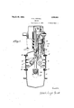
llVith these ends in view, my improvements include elements, and combinatlons of elean upstanding ments which are illustrated in theiri'pre'- ferred embodiment in the 'drawings accom-v panying this specification wherein Figure 1 isa vertical view, partly in cross section, of the engine;
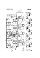
Fig. 2 is a plansectional view showing the location of the cylinders in dotted outline and of the Vcrank case and one power transmitting lever in full lines; i
Fig. 3 is a diagram showing the' firing order of the cylinders and Fig. 4 is a longitudinal view of the 'crank shaft. I Y
vThe invention is shown herein as embodied in an engine employing eight cylinders, two banks being provided, each having four cylinders therein, although thel principles thereof are in theinain applicable to `any even number of cylinders. f
Referring more particularly to the drawings, 1 represents' a crank case having inserts 2 consisting of rectangular vplates'carrying. inwardly extending bifurcated supports 3. Suitable means, suchv as the bolts 4, are provided whereby the 'plates' 2 may be suityably secured to the crank case 1. Aligned apertures 5 extend throughthe supports 3 and'provide a bearing for a pin 6, which .pin serves as 'a fulcrum point for a lever `7 which lever is Vat'itsl other end connected to the piston 8 by means of a connecting rod or piston p 9, which piston is slidable in'awat'er jacketed cylinder 10.
A crank shaft'11, having cranks 12, is carried in the lower portion of the'crank case l, 'being supported by bearings 13, 14,v and 15, vwhich bearings are in turn carriedVv by later- 'ally extending portions 16, 17, and 13 of the crank'case 1. Located midway between the bearings 13 and 14 is a bearing 19 Ycarried by portion 20 extending from the bottom of the crank case 1. A similar l bearing 21 is provided intermediate the bearbanks of cylinders', the
ings 14 and 15, the crankshaft being provided with alignedvbearing surfaces 21, 22, 23, 24, and25, adapted lto be carried in the bearings 13,
The' cylinders'are arranged in two rows or banks, which banks vextend longitudinally of the engine on the opposite sides of the perpendicular plane passing through the 19, 14, 21, and 15, respectively.
axis of the crank shaft. The cylinders on the leftliand side of the engine are denoted by the reference characters 1L, 2L, 3L, and fil, respectively, and those on the righthand side are denoted yby thereference characters 1R, 2R, 3R, and 4R, respectively. A 'fulerum support 3 is provided in the same transverse plane with Jeaeliof .the cylinders. It `is .to be noted that thecylindersofone :bank are arranged in staggered relation with thei cylindeis of the other bank, any three adjacent cylinders, (two in one bank landone in the other bank) forming the vertices of a `triangle Any one or more of `these cylinders could beV fired Aat any given time, vbut 'I have found that the torsional effects on the crank shaft are minimized or practically eliminated by `firing the explosive charges in two cylinders simultaneously spaced a substantial distance apart. n'
VIn.my preferred construction, the firing .order of the .cylinders is as follows 11' and 3R simultaneously;
,3L .and 1R simultaneously:
4L 'and 2R simultaneously; and
2L and 1R simultaneously.
It is to be noted khatin the above inentiovned firing order one of the cylinders in one bank explodes simultaneously with one A"of the cylinders in ,the otherbank, and that these two cylinders are spaced apart by a `distance at least equal to one-half the length of the crank shaft.V At least two cylinders are interposed between the itwo cylinders that are firing. The above mentioned firing .oi-,der is the onewhich I haverfound to be the best, but the' essentialfpoint is that .the ltwo cylinders which .fire simultaneously should be spaced apartlongitudinally of the crankshaft by a considerable distance. If only .six cylinders are used, I would` recommend the ffollowingfirin order:-
yl and 2R simultaneous y; i
1R and 3L simultaneously; and
2L and 3R simultaneously.
Referring to Fig. 4, itis to be noted that y all ofthe cranks 12 of the crank shaft are in the same plane. Fig. 3 represents a diagram showing the order of the explosions. If Fig. 3 is taken in conjunction with Fig.
' 4, it will be seen that the pistons in Fig.
3 are directly above the respective cranks with .which they would be connected in Fig. 4. l
While I have shown my preferred construction by way of an example, it is obvious that many changes may be made in the specific structure herein shown without departing from the fspirit ofthe; invention. I, therefore, do not limit myself t0 the spe-l ciic structure shown, except as I may limit myself in the following claims.
What I claim is l. An engine having two rows of cylinders, the plane passing through the axes of the cylinders of one row being 'parallel to the plane passing through the axes of the ycylinders in lthe other `row .and means for ...firing .explosive charges in .two .of said cylinders simultaneously said last mentioned `cylinders being spaced apart by a distance `atleast equal to one-half the length of the a distance at least equal to one-half the length of the engine so that the engine is almost perfectly balanced.
3. An engine having two rows of cylinders, the cylinders vof one row being arranged in staggered arrangement with rela,- tion to the cylinders of the other row, said cylinders having a firing order whereby'the explosive charges in two of said cylinders are fired simultaneously said last mentioned cylinders lbeing spaced apart by a distance at least equal to one-half the length of the engine :sothat the engine is almost perfectly balanced.
4f. An engine having two rows of cylinders, the cylinders of one row being arranged in staggered arrangement with relation to the cylinders of the othery row, said cyliii- .ders having a firingorder whereby the explosive cliarges in one cylinder of each row vare fired simultaneously the firing cylinders being spaced apart so that at least two cylinders are interposed between the cylinders that are firing whereby a balancing of the engine `is obtained.
5. An engine having akplurality of cylinders in two banks, the plane passing through the axes of the cylinders of one bank being parallel to the plane passing through theaxes of the other bank, pistons therein, va crank shaft, means operatively connecting said pistons and crank shaft, the
' firing order of said cylinders being such that the harges in two cylinders fire simultaneously, such firing cylinders being spaced apart by a distance equal toat least onefourth the length of the crank shaft whereby the unbalanced vibrations of the engine are neutralized envian Linien POWELL.
Priority Applications (1)
| Application Number | Priority Date | Filing Date | Title |
|---|---|---|---|
| US700308A US1663261A (en) | 1924-03-19 | 1924-03-19 | Engine |
Applications Claiming Priority (1)
| Application Number | Priority Date | Filing Date | Title |
|---|---|---|---|
| US700308A US1663261A (en) | 1924-03-19 | 1924-03-19 | Engine |
Publications (1)
| Publication Number | Publication Date |
|---|---|
| US1663261A true US1663261A (en) | 1928-03-20 |
Family
ID=24813018
Family Applications (1)
| Application Number | Title | Priority Date | Filing Date |
|---|---|---|---|
| US700308A Expired - Lifetime US1663261A (en) | 1924-03-19 | 1924-03-19 | Engine |
Country Status (1)
| Country | Link |
|---|---|
| US (1) | US1663261A (en) |
Cited By (3)
| Publication number | Priority date | Publication date | Assignee | Title |
|---|---|---|---|---|
| US2659351A (en) * | 1950-01-23 | 1953-11-17 | Lever Motors Corp | Internal-combustion engine |
| US2757547A (en) * | 1953-08-03 | 1956-08-07 | Zeniph J Julin | Universal double torque engine |
| US5448970A (en) * | 1995-01-12 | 1995-09-12 | Bray; William R. | Crankshaft connection for internal combustion engine |
-
1924
- 1924-03-19 US US700308A patent/US1663261A/en not_active Expired - Lifetime
Cited By (3)
| Publication number | Priority date | Publication date | Assignee | Title |
|---|---|---|---|---|
| US2659351A (en) * | 1950-01-23 | 1953-11-17 | Lever Motors Corp | Internal-combustion engine |
| US2757547A (en) * | 1953-08-03 | 1956-08-07 | Zeniph J Julin | Universal double torque engine |
| US5448970A (en) * | 1995-01-12 | 1995-09-12 | Bray; William R. | Crankshaft connection for internal combustion engine |
Similar Documents
| Publication | Publication Date | Title |
|---|---|---|
| US1663261A (en) | Engine | |
| US2957455A (en) | V-six engines | |
| US1881027A (en) | Reciprocating engine | |
| US1792062A (en) | Internal-combustion engine | |
| US1734489A (en) | Internal-combustion engine | |
| US1347087A (en) | Compound quick-combustion engine | |
| US2303025A (en) | Internal combustion engine | |
| US1722950A (en) | Internal-combustion engine | |
| US2680427A (en) | V-type engine | |
| US1656884A (en) | Form of internal-combustion engine | |
| US1946718A (en) | Internal combustion engine | |
| US1811625A (en) | Two cycle radial engine | |
| US2287224A (en) | Internal combustion engine | |
| US1885576A (en) | Internal combustion engine | |
| US1094431A (en) | Gas-engine. | |
| US1623387A (en) | Internal-combustion engine | |
| US1665521A (en) | wrentmore | |
| US1708901A (en) | Internal-combustion engine | |
| US2666418A (en) | Means for balancing piston engines | |
| US1720261A (en) | Internal-combustion engine | |
| US2078692A (en) | Engine construction | |
| US2159209A (en) | U-type two-cycle radial engine | |
| US1623391A (en) | Internal-combustion engine | |
| US1679958A (en) | Internal-combustion engine | |
| USRE21177E (en) | Internal combustion engine |